

Need some help developing for Bonsai - Working on modeling an Alignment

I am trying to add a UI for modeling alignments in Bonsai for infrastructure and I'm really, really stuck.
I have gone through the "Demo" panel example for Bonsai, and have been able to create a simply test panel with a button on it.

I can respond to the button press event and create an alignment, but I have no idea how to get the alignment to show up in the scene collection or in the 3D viewport.
I've got a branch in the IfcOpenShell repository called alignment_modeling_experiments. If you look at the tool code in https://github.com/IfcOpenShell/IfcOpenShell/blob/alignment_modeling_experiments/src/bonsai/bonsai/tool/alignment.py you'll see where I'm stuck.
I can create the alignment, save the IFC file, then reload the file, and the alignment shows up as expected. I am stuck on getting the alignment to show up while in an editing session.
If you so inclined to run the code to create the alignment, just create a new IFC4X3 project from the wizard, the scroll down to the bottom of the Project Overview tab to find the "Alignment Demo" tab
I am hoping the solution is something simple and one of the expert Bonsai developers can point me to it.
Thanks.
Comments
Use
convert_geometry_to_mesh, and create a Blender object :)Thanks so much - that did the trick. Can you help me understand what is going on with the code and how things are named?
Here is the code
class Alignment(bonsai.core.tool.Alignment):
@classmethod
def build(cls):
coordinates = [(0.0,0.0),(100.0,0.0),(200.0,200.0)]
radii = [(50.0)]
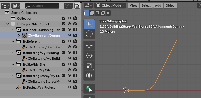
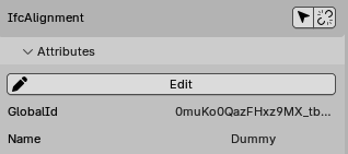
I get what I expect, an IfcAlignment named "Dummy"

There is a new Blender object named "Foo" and its geometry is a mesh named "IfcAlignment_Mesh"
When I save the file and re-open it, things are a little different in the scene collection.
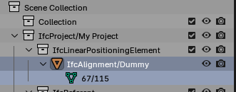
What's going on?
You can use
tool.Loader.get_mesh_name_from_shape()andtool.Loader.get_name()to set the mesh and object names as per the Bonsai naming convention.Instead of hardcoding a reference to every site, you can use
tool.Root.get_default_container()which will reference the user's actively chosen container in the spatial hierarchy panel (admittedly, it defaults to the storey in our current wizard defaults, but let's assume by then we have a nicer infrastructure modeling default preset in the wizard).Thanks for the tip on naming. I think I’ve got IfcAlignment referenced in spatial structure of IfcSite correct. For a road alignment with multiple sites, the alignment isn’t contained in any one site rather it passes through the sites and is referenced into each site.
Hello everyone,
I'm joining this discussion because I hope it might be of interest to you. I'm developing a Python-based workflow in Blender to replicate Civil 3D’s infrastructure modeling process, aiming to create an open-source pipeline for the design of linear infrastructure (roads, railways, pipelines, or any project primarily extending in one direction).
🔹** Civil 3D Workflow to Replicate**
The standard Civil 3D approach for infrastructure modeling typically follows these steps:
0️⃣ Building the Topographic Surface (EG - Existing Ground)
1️⃣ Defining the Alignment based on planimetric data.
2️⃣ Studying the Elevation Profile
🔁 Note: Steps 1 and 2 are iterative, meaning any modification at any stage affects the entire workflow. Each change triggers a full recalculation of the model.
3️⃣ Generating the 3D Alignment, combining horizontal and vertical geometry.
4️⃣ Placing Cross-Sections Along the 3D Alignment
5️⃣ Lofting Between Cross-Sections to generate the final 3D solid.
⚠ Critical Issue: One challenge that might prevent a valid 3D solid is when two cross-sections intersect. A method is needed to handle these cases and prevent errors in the final geometry.
🔹 Current Progress in Blender
I’m still in the early stages of development, but I have already implemented a Python script that:
✔ Creates a 3D alignment from planimetric and elevation data.
✔ Generates cross-sections along the alignment.
✔ Builds parametric modeling planes to calculate project-specific cross-sections.
I don’t have much experience with Blender, so I’m unsure if I’m taking the right approach. If you're interested, I’d be happy to share my code and discuss ways to improve it.
Once the 3D solid is generated, the next step will be to ensure proper IFC integration for BIM workflows.
What do you think?
It's perhaps worthwhile to work backwards as well as forwards. By this I mean seeing how IFC defines alignment curves and lofts between cross sections. Here's a good place to start: https://wiki.osarch.org/index.php?title=IFC_-_Industry_Foundation_Classes/IFC_alignment
Then when you do generate horizontal, vertical, and finally combined alignments back in your step 1-3, you're already doing it using the IFC data model. This means that everything already works in Blender / Bonsai - you just need to create a good interface for it.
Super!
I think we also need the part where the user can define the Assembly and set daylights
I'm very happy more people are on this topic, thanks
Hi everyone,
@Moult, do you have any suggestions on how to structure a good interface for managing alignment and cross-sections in Blender/Bonsai? Is anyone already working on this aspect?
@steverugi, I completely agree that defining the Assembly is one of the most critical parts. We are dealing with parametric objects that must adapt to the environment based on specific design rules, such as slope constraints, minimum widths, and terrain intersections.
Having an intuitive interface for editing the "linear infrastructure model" is essential to ensure a good and reliable design experience.
Additionally, regarding UI development, I recently purchased "Python Scripting in Blender: Extend the power of Blender using Python to create objects, animations, and effective add-ons", but I haven't had the chance to go through it yet. Besides this, are there any recommended guides or references for creating graphical interfaces in Blender?
Cheers,
Francisco
@FraJoMen
I just finished reading that book. Very good information. It provides a detailed view of how add-ins work for Blender. As you dig through the Bonsai code, you'll see parallels with the book. The book and the "Demo Model" in the Bonsai documentation (https://docs.bonsaibim.org/guides/development/hello_world.html) was enough to get me started hacking. What I found missing was a deeper dive into the bpy API and creating custom UI elements.
Here are links to some ongoing efforts for infrastructure UI/UX:
https://github.com/opencax/GSoC/issues/98
https://community.osarch.org/messages/219#Message_1574
https://github.com/IfcOpenShell/IfcOpenShell/issues/5638
https://github.com/IfcOpenShell/IfcOpenShell/wiki/Infrastructure-Authoring-‐-Design-and-Coordination
Yeah I think Bonsai pushes the boundaries on what most addons do in Blender :) I don't really know what to comment since I don't have any experience in infra modeling (see https://github.com/IfcOpenShell/IfcOpenShell/issues/4933#issuecomment-2666862585 ) but if someone can help explain in detail what's needed we can do some pair programming where I help do the beginning and point out what can be reused (we've probably already written a lot of similar UI code which can be revamped for infra).
Hi everyone,
@Rick_Brice, thanks a lot for sharing all this material! I’ll go through it as soon as possible.
@Moult, I’m really glad to see your interest in expanding Bonsai in this direction. I’ve also joined the GitHub discussion, preparing a short presentation on infrastructure modeling. Unlike architecture, infrastructure is mostly a 1D object in a 3D space, making modeling simpler in some ways but introducing unique challenges.
Recently, I had the pleasure of discussing with @steverugi, Nana Atoeku-Frans, and Kevin Kevin Schnippkoweit (not sure of his username here):
Although I’m new to this community, I see great potential but also a lack of coordination among resources. It would be great to discuss how we can align our efforts to maximize synergy.
As a hands-on engineer, I’d suggest creating a simple case study to test and refine the entire workflow. I could try developing a test case by pretending to be a new Bonsai user—though, to be fair, that wouldn’t take much effort, since I actually am one! 😄
What do you all think would be the best way to improve collaboration?
Looking forward to your thoughts!