

I need a IfcDistributionSystem and Circuit doctor - anyone?

from a different discussion
Has anyone figured out how to implement IfcDistributionSystem/IfcDistributionCircuit in Bonsai?
not the part where elements (segment/fitting) are assigned to one system and connect via ports, that's clear
I am after a simple example of a circuit, part of a larger electric system, completed with flow control
distribution board > breaker > segment > junction box > segment > switch > segment > light
I think the same principle can be adopted in plumbing lines
I'd be eternally grateful if someone could show me the way, I can see the UI has seemingly all in place already.
Cheers


Comments
Is it possible that noone has ever used Bonsai for electrical or plumbing systems? any help from developers please?
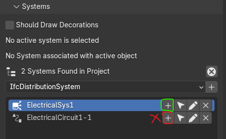
I can create an IfcDistributionSystem and an IfcDistributionCircuit
assigning conduits, switches and outlets to the former is achieved by selecting them and click on the + next to the electrical system but I don't understand how to assign elements to a circuit
question 1
from the IfcDistributionCircuit page
I understand that a circuit (logically) is a sub-system where a device controls the elements within it
like a switch through cable/conduits controls a light
the same circuit can also aggregate multiple sub-circuits
all good but how to achieve this in Bonsai?
question 2
from the same page
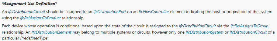
OK, makes sense, so I create an IfcSwitch with port (connected to pipes > light) , which should be the " An IfcDistributionCircuit should be assigned to an IfcDistributionPort on an IfcFlowController element indicating the host or origination of the system " thing
When I try to add that port to the circuit it triggers an error
Same applies when I try to add the switch to Flow Controls..
(it would be nicer if just a warning popped up instead of an error here maybe)
comment
if our beloved Bonsai is not (yet) there it's totally OK, I can patiently wait or do my best to contribute, but if the feature allows more than creating a system and add elements to it I don't see why it can't be explained so that users can leverage on it.
In my point of view it's not a trivial issue, MEP system are as important as the rest of a model, lots of money there, and I suspect they are the main source of problems in clash detection too..
many thanks
ping @Moult (who is extra-super-busy but maybe he can explain something about the above, if possible and when available)
I think the UI to create the hierarchy is not implemented yet (since IfcDistributionCircuit indirectly inherits from IfcGroup)
For me the error happens for any element to be assigned.
Issue #6202 opened.
The control part I still don't quite understand, but I've made some progress:
Ps: Just for the record, if anyone is looking for this in the future, these links shed some light on the ports issue:
IfcDistributionSystem should indicate when distribution ports should be assigned to a system
IfcSystem should group IfcDistributionPort-s or not, if IfcDistributionElement of the port is part of the group?
@walpa
thanks I am going to check it right away
I am sure all together we are going to soon solve the MEP riddle in Bonsai :D
cheers
My questions regarding cable modeling:
1 - Today, the Cable Tool models the element type from extrusion on the polyline tool, creating a sequence of cylindrical meshes, separated by section.
2 - I understood that in IFC each cable is modeled separately with its descriptive psets, and they are grouped in IfcDistributionCircuit, along with ports, switches, lamps and everything else.
@walpa
I agree, I too think a simple polyline/curve (geometrically speaking) is more than enough to define the cables, I see little point in extruding/sweeping it.
Not too sure but maybe the takeoff part can be sorted out as long as we have a valid geometry, it only needs to be implemented
Good point. Once the conduit or cable tray/ladder are associated with the relevant carried cables' info the quantity could be derived from that, maybe?
Often times on site the conduit/cable laying is left to the intepretation of the electrical contractor who logically but not spatially follows the single-line diagram.
If BIM modeling goes to that level of details with actual carrier segment going through its expected alignment it shouldn't be an issue nesting cables (even just logically and not physically) and let the port connections do the job of making a circuit/system.
Thinking aloud here but I feel that cabling in most cases doesn't even need to be modeled (you won't see it anyway, same applies to inner shape of a pipe for instance), but I am relatively new to BIM so forgive my being naive, is it actually needed a port connection for all cables to breaker or switch terminals ? I genuinely have no idea.
Thanks for the exchange
Maybe two feature requests:
I have some doubts:
I think it depends on the use case.
1 - for coordination/visualization:
2 - for takeoff:
3 - for electrical calculations:
4 - for control and automation:
@walpa
If I had the chance to design the procedure I would propose it as follows:
Say you have your circuit/system well laid out using terminals, conduits,trays, ladders, lights and so on, no cables.
Now it's time to pass your cables from end to end, so
in this process there is no 3D geometry involved, just terminal/carrier selection. Bonsai (if ever possible) should understand the start and end ports based on the selection and assign them to itself, and maybe create a simple nice line, similar to what we already have when you click on
Should Draw Decorationswith flow directionuseful info, much appreciated
thanks
Note
the procedure above implies that selected terminal/carriers are already into source > sink continuous connection, this way it shouldn't, I suppose, be so difficult to create the passing cable..
yes, it would be fantastic that way, even more so if it were possible to edit the resulting polyline after creating the cable, allowing for a more complex path
I can't answer your question as I am also trying to do this by trial and error, but it would be helpful.
Have you found the documentation for IfcDistributionPort?
IfcDistributionPort seems to be related to each other, and IfcPipeSegment or IfcCableSegment in between seems to be optional.
thank you @KoAra
very useful information
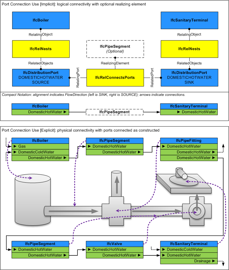
The way I see it, as also indicated in the image, elements (eg IfcBoiler.water and IfcSanitaryTerminal.washhandbasin) can be connected logically or implicit - no geometries-, or explicit with all the parts. In both cases ports are connected and flow is established (source > sink)
In the example, being a plumbing system, only IfcPipeSegment was used (no cable) but it helps understand connection port to port. The same can already be implemented in Bonsai, which is cool.
Cheers
Connections must be explicit due to their later use in the algorithm logic, e.g. hydraulic or electrical calculations, and for the needs of automatic detection of whether all elements are connected (both visual and program verification). Elements not connected via ports should not be counted and programmatic data validation should occur. Unconnected elements should have a distinction for easy visual identification, e.g. an exclamation mark next to an unconnected port, then the user can see which element is incorrectly connected to the rest of the part.
Of course, the above is a proposal of an approach based on my experience with other programs, which is really helpful in design.
@hydromac
good idea, like with the Bill of Quantities panel where you can show which elements are accounted in the schedule or not
thank you