

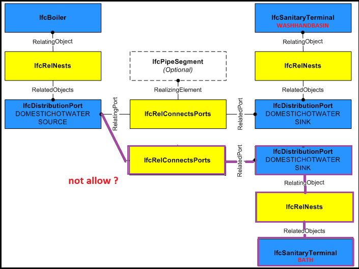
IfcDistributionPort not allow from a port to some port

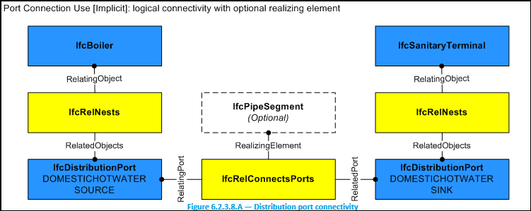
I tried to set up an IfcDistributionPort in Bonsai. Figure in the IFC document shows the connection of the boiler to the sanitary terminal wash hand basin. Hot water is good for hand washing in winter.
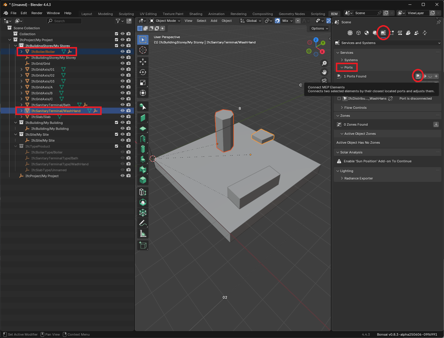
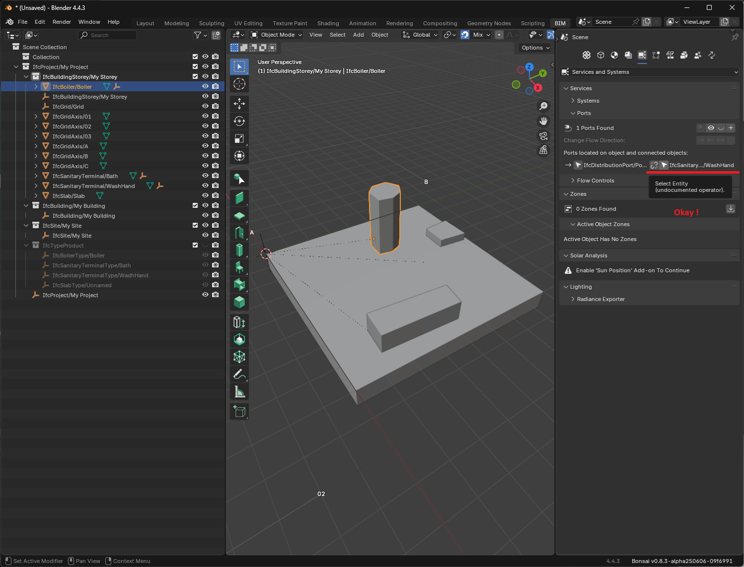
This connect relation was made with Bonsai.
However, when I tried to add a second sanitary terminal bath, I got a warning message that there were no free ports for it.
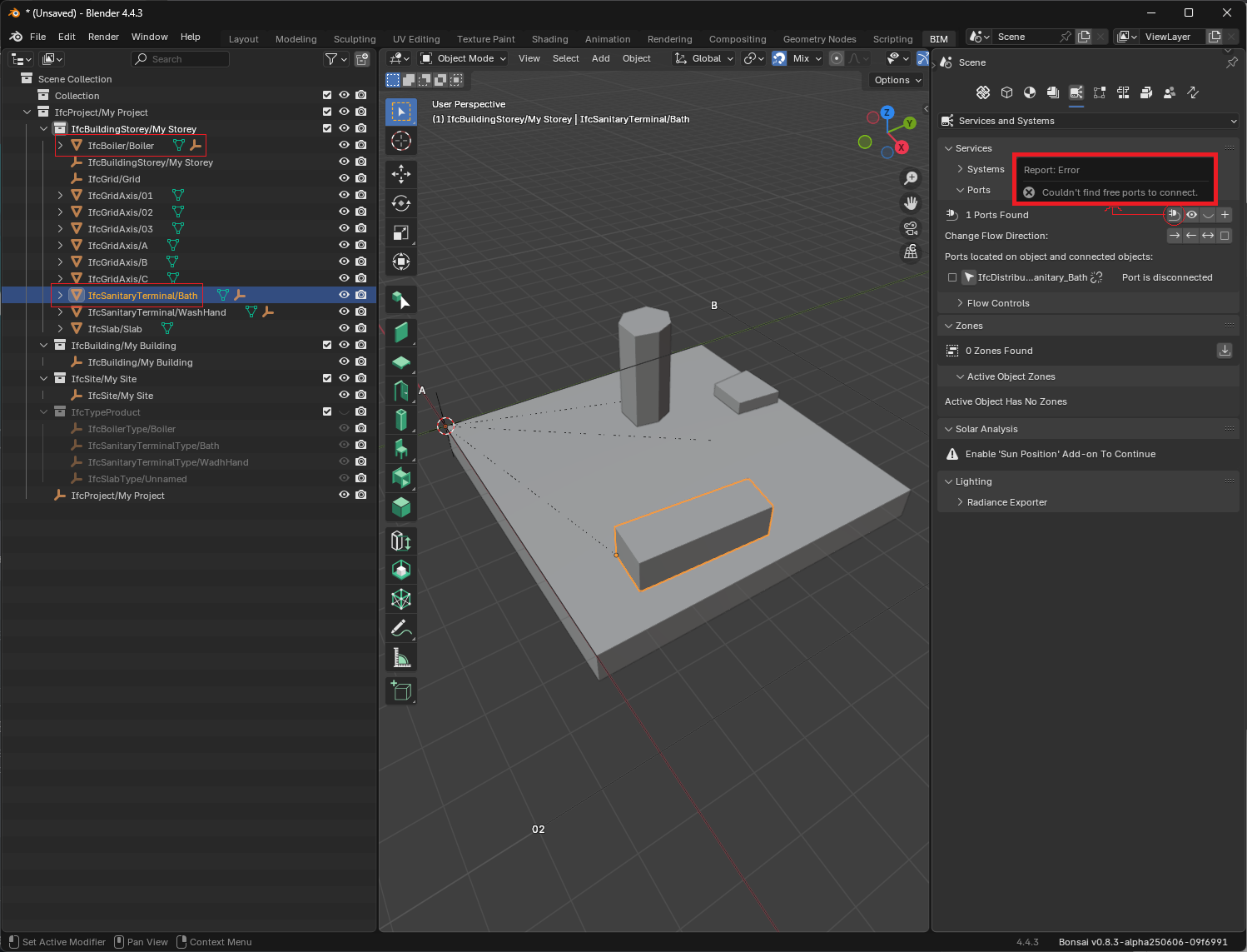
Does the IFC documentation not allow connections from a port that is a SOURCE to some port that is a SINK?
Please point out if my manipulation of Bonsai is incorrect.
Thx ;)
Tagged:

Comments
Hi @KoAra
I tried to play a bit with the system
distribution ports have one connection to another distribution port, I think you need to create a fitting (JUNCTION) with 3 ports :
detail of my rough fitting:
distribution ports, as indicated in the image on the webpage, need to have SOURCE/SINK to assign the flow
I suspect the predefined type of the port should also be consistent (like DOMESTICHOTWATER), it's a bit of hit or miss game here
unfortunately the editing is a bit tedious, connecting elements often times scatters them all over the place, but the attached file hopefully should be something you want to look into
I wish someone with more knowledge on the subject came here to add some professional advice
cheers
see if the diagram here could be of help too:
Thank you for your comment. It is good as one how-to.
On the other hand, I think IfcRelConnectsPorts has IfcPipeSegment as optional so that IfcDistributionPort can refer to connect relationships between entities such as equipment. If it had to be related to the Fitting JUNCTION, I thought it would be harder to understand the relationship between equipment.
The third Figure in the IFC document also contains PipeSegment, Fitting and Valve, but how is it correct to interpret this as a relation to the first Figure? :)
As far as I understand the difference is between "implicit" -top or "explicit" bottom
The first defines logical connections whereas the second the actual (physical)one.
A logical/implicit still needs to work with a 3-port fitting to have two terminals from the same boiler
Again, I'm not an expert, just trying to make sense of what available
I agree with @steverugi.
How I understood this part:
Implicit: it is not necessary to model the pipes and fittings, the source element (I think with the necessary number of ports) connects directly to the target elements (sinks). For example, to calculate the capacity of a boiler it is not necessary to know which pipe to use (without going into the issue of standards for this part here) but it is necessary to know the consumption of each sink. Creating the direct connection can avoid the complexity of having to evaluate the entire network.
Explicit: when you model everything how it will be built
I think that (again) it depends on the use case.
Honestly, I have difficulty accepting the modeling of a system with a boiler being connected to a sanitary terminal without pipes. In real life things are not like that.
Cheers
@walpa
Maybe to draft a system in a logical fashion, without knowing the exact location of the terminals, valves, segments.
You can practically abstract an entire building like that.
Ifc is also for these kind of things, no geometry, only virtual objects with metadata and relationships. maybe?
@steverugi , yes, perfectly plausible.
The construction engineer fighting the cost engineer in me... :)
@KoAra , @walpa
here an updated simple model, now with faucets (taps), still basic but maybe useful to start
to connect ports they can be selected in the Outliner with "Show Ports" activated, one day the UI will be more user-friendly but it's doable for small systems I think.
Help
I'm still trying to figure out how to add a "Flow Control" to operate circuits by the way, does anyone know?
cheers
@steverugi , I was able to make the relationship for electrical circuits as shown here.
For fluids I couldn't find it:
IfcSwitchingDevice can be replaced by IfcValve, but I couldn't find a match for IfcProtectiveDeviceTrippingUnit.
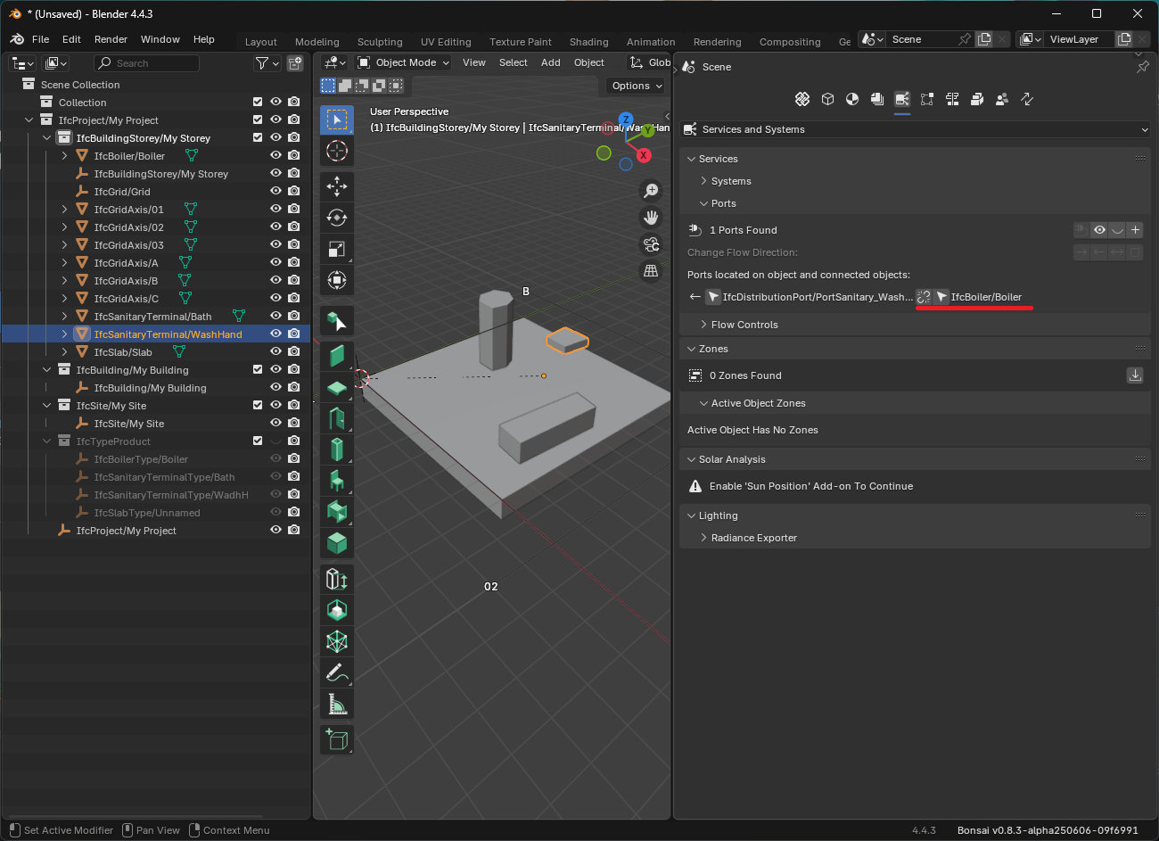
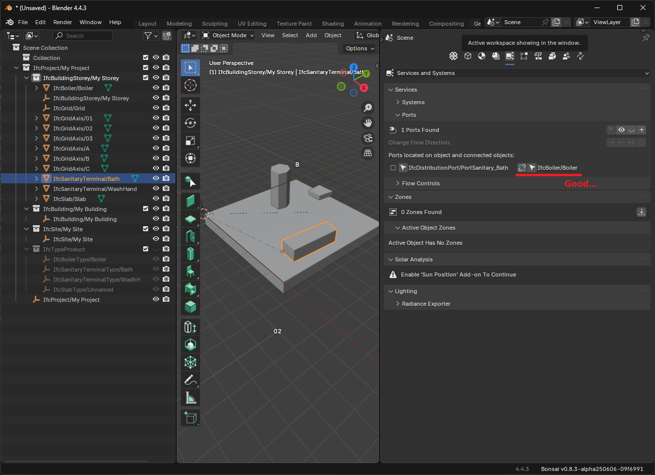
I forced IfcRelConnectsPorts from one SOURCE side Port (Boiler) to the second SINK side Port (Bath) using a text editor.
I was able to open this IFC in Bonsai, and the Port on the Sink side is able to reference the Boiler in both WashHand and Bath. However, Boiler's PortConnects shows only WashHand and not Bath.
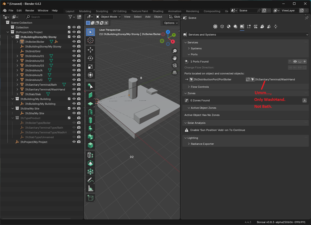
Again, IFC does not allow connections from a port that is a SOURCE to some port that is a SINK?
@KoAra
I am not sure about what you are trying to achieve here, I only know that distribution ports are there to connect system elements and they must be into a one-to-one relationship, in such case one is the SINK (flow inlet) and the other is SOURCE (flow outlet).
So: 1 system element may have several ports but each port must be connected to only one port on a different syestem element (if you think about the flow it makes sense)
In your case you have a washbasin and a bathtub plus a boiler, I was hoping my diagram above was sufficiently clear
please advise, thanks
Oh, I couldn't find it, but as you say in IFC it is connect system elements and they must be into a one-to-one relationship.
If that is the case, then a DistributionFlow that branches into more than one cannot be modeled unless you put in a Fitting JUNCTION or something like that.
I wanted to give information on flow with DistributionPorts to the source of connection and sink with equipment only, without modeling the piping and ducts. Because the piping and duct routing would change until the end of the design to avoid interference. That approach doesn't seem to be possible.
Thanks for the reply :)
@KoAra
Yes
You can still have a logical system using a fitting JUNCTION right? so one of its port (SINK) connects to the SOURCE of the Boiler and the other two would be SOURCE to the connected ports from the two pieces of equipment
sure
I found an explanation in the Ifcopenshell documentation.
I am an electrical designer, and while most electrical cables are connected in one seamless run, plumbing designers have a hard time tracing port connections because the Fitting of the plumbing duct is a JUNCTION. Ummm.
There is implicit connectivity to show the port connection relationship between the equipment and implicit connectivity to relate the ports of the equipment to the flexible pipe segment.
I came up with the idea of having both of these exist in BIM. However, it will take some time to make sure they are both consistent. Ummmmm.