

A Standard BIM workflow in Bonsai| Arch, Structure, MEP

I have been doing small scale projects, and all my structure, MEP, architectural elements are in a single file. But now I am thinking of splitting them , so as multiple people can work separately. I got this workflow from claude--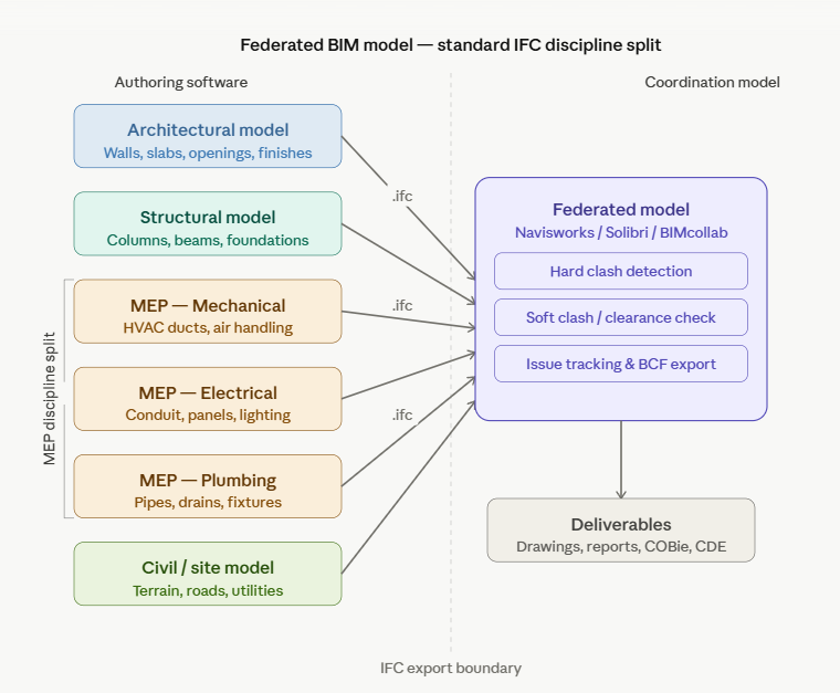
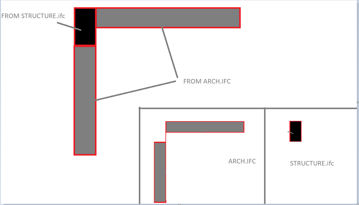
But my confusion is that when the structure is separated from the architectural wall elements, the architectural plan will have voids?
In this scenario, how bim coordination is done in bonsai. LinkIFC should be used? I mean can we generate drawings with elements from multiple files.
what is a better approach. Or just work in a single file? Experts please advise.
Tagged:


Comments
That is exactly how it is really done for larger commercial or industrial projects. Structure is controlled by the engineers and therefore their BIM model part.
Where Structure here means everything load bearing, like Roof, Slab, Columns, Beams but also load bearing Walls, maybe also parts of Stairs, Curtain Walls, .... Architecture may get the rest like Floors, Insulation package, Interior Walls, Windows and Doors. Basically the Coverings :)
But of course each party influences the work of other parties. Constant communication and collaboration is mandatory. So that Model separation may be cumbersome.
Depending on the size and complexity that is separation of architectural and structural may not be needed and if you have the chance to avoid that separation - if possible, just keep it together.
Maybe even the Site Model, in case you control that too. While as an architect you may not want to edit MEP or Process stuff in your Model but attach them as a References. For a single family residential project, the architect may do all himself in a single Model. Landscape design, plumbing, electricity, ... an engineer or even a builder may check structure only once or maybe a second time in case the design changed.
That is how I thought how IFC Linking is meant and the way I use it (similar) in other Software (by referenced files).
But I have no experience if that is already usable and reliable.
Are these other peeps using Bonsai (or Freecad) as well?
Ahm, I was assuming that these peeps (at least for Structural and Architectural) are working mainly in the same building or at least same company (!?) So likely all Bonsai (?)
I initially even got sectioning of the whole Architecture for collaboration by multiple people in my mind - like by Story or even by IFC Elements or so .....
Otherwise, there would likely be already any kind BIM Manager/Coordinator that already dictated the needed IFC separation ?
Something I naively just thought to be god given ..... but no experience ..... and also very interested if LINK IFC is a way to go .....
If they're all using Bonsai or Freecad (which uses NativeIFC), i would recommend keeping all the disciplines in one model, and using @brunopostle's awesome IfcMerge tool for distributed version control of ifc files!
(Not that I would really know or understand Bruno Postle's awesome IfcMerge tool for distributed version control of ifc files! or the whole thing ....)
@theoryshaw ....
Hmmh, so you are you would discourage using the default Separation, Referencing, Clash Detection, ..... approach ?
(likely for valid reasons)
I immediately think about MEP, HVAC and electric stuff that in my experience likely has each x times the file size than your whole architecture and structural Elements together - which you want in your file which may need to be saved and backup-ed on a slow server drive.
And collaboration,
of multiple people is still possible by a single IFC file that way ?
I think it’s better to set the placement using an IfcGrid rather than an IfcBuiltElement, but it’s difficult to do.
Hmmh, ok ....
I just had to think of my worst project example ever where each of the MEP disciplines had 500+ MB IFC Files where you could not even work comfortably with one of them or ever combine all disciplines in a BIM CAD. But such projects should be pretty rare.
As so far all disciplines were combined in a single File, file size should not be the issue in this case. So I withdraw that point.
@arunarchitect
What proposed by Claude above doesn't represent an issue in my case, since I use IfcCovering.CLADDING - vertical layer - for plastering (like in real life) so voids won't show so bad in the ARC model.
I like splitting the whole model into disciplines too, even when I am the only one converting DWG to IFC, but my primary deliverable is not drawings, already available, rather schedules for data analysis.
I did try using multi-layer walls including plaster but voiding to subtract concrete elements turned out to be more complex than aggregate into IfcElementAssembly and share the void across the parts (there is still a bug hanging there as of 260415 unfortunately), the bigger issue with multi-layer is that quantities become difficult to handle when walls are voided by columns/beams/slabs, where only the external layer, or plaster, is the one determining the overall length or area, not the nested block.
I either use the Link feature to model (concrete structure going first- again like IRL) or same grid lines location, which I normally set crossing of A and 1 as 0,0,0 leaving to geo-referencing the rest.
I would love to see what others do (Yes GIT is a phenomenal way of coordinating design development, thanks Bruno!)
Cheers
@arunarchitect There is a major shift coming. I am not so sure you want to put to much effort in to this just yet. All AEC software programs who wish to remain relevant are in the middle of a major transition. This actually started in the film and VFX market. As it turns out they have similar problems as the AEC market. They have a file (in their case a movie) and they have literally 100's of designers that need to work in the same file at the same time and those files can get quite large. They tend to work in Linux in the data center because of that. Pixar was the first to create new tools to help them with their workflow and they worked so well they released them to open source. they are designed to allow collaboration of graphics files across software programs. Pixar created OpenUSD and the Hydra Rendering Frame work. Open USD is designed to allow multiple designers to work on graphics files simultaneously. each designer works in their own layer and the layers are non destructive. If someone else designs something that clashes the clashes are visable to everyone in real time. These are called scene graphs. AutoDesk, Adobe, and Nividia are already on board. As a matter of fact Nvidia has video driver support for their GPU's for OpenUSD. At the same time there is a new API called Vulkan that is replacing the OpenGL api that has been around since 1992. One of the disadvantages of OpenGL is it is single threaded so id doesn't matter how many cores your CPU has your CAD modeler uses only one of them. Vulkan is multi-threaded and supports multiple cores! Vulkan provides much lower access to the GPU's and allows programmers to address those GPU's in new and creative ways. this is how they relate to one another:
OpenUSD scene/data layer
→ MaterialX (actually sits beside or slightly below OpenUSD)
→ Hydra imaging/rendering framework
→ Hydra render delegate
→ graphics abstraction / renderer backend
→ Vulkan
→ GPU driver / hardware.
MaterialX was created by Industrial Light and Magic and Lucas Films to perserve the look of a movie from one software program to another it is also a open source API that works with surfaces and bit maps.
Now the organizations behind OpenUSD and OpenBIM and inked a liason agreement where by the Open BIM schema will run on top of the OpenUSD Graphics engine. You can already see bits and pieces of this showing up in Blender.
Now the organizations behind OpenUSD and OpenBIM and inked a liason agreement where by the Open BIM schema will run on top of the OpenUSD Graphics engine. You can already see bits and pieces of this showing up in Blender.
What that means they need to change ifc standard or usd would have made compatible with ifc ?
@isain
It means that regardless of the entire world finally moving to IFC as (ISO) standard, progressively adopted by governments to regulate construction permit and public works above some amount, there always be someone every now and then popping up with something like "USD is the future".
So outside of Disney World, when it comes to hard reality, I'd advise to stick to IFC, keeping an eye on IFC5 to see if in a few years something workable emerges..
Cheers!
You will lose that Dog fight AutoDesk Adobe and nvidia have already signed onto OpenUSD and BuildingSmart has signed a Liaison agreement to run the openBIM schema on top of OpenUSD the fight is already over you just haven’t received the memo yet…
No Open USD addresses graphics, Open BIM addresses Data the two are complimentary not adversarial
@arunarchitect, for your consideration for a small project, if you want to use LinkIFC then you may have to go the old school approach in proprietary software.
That is one of the reasons why, in Revit categories, you can find both "Columns" and "Structural Columns" under Object Styles. The architect uses columns, and the linked Revit file from the Structural Engineer uses the Structural Columns.
So this is what I would advise: within the native ARCH ifc file, keep duplicates of the columns, and in the Pset_ColumnCommon, leave the LoadBearing property unchecked. You can always use this property to filter out the ARCH columns anytime you link the STRUCT columns (LoadBearing=True).
Otherwise, the IfcMerge is the way to go, as earlier mentioned by others.