

[BlenderBim] How to import ifc with large coordinates?

So the problem is, I received some ifc files from a planner. However, when I checked the IfcCartetsianPoint, I realized they gave me the ifc file with real world coordinates instead of local coordinates which are relative to a project zero point.
So is there any way in BlenderBim when I import the ifc that I can give x,y,z values first so that BlenderBim does a displacement first before loading it into Blender -> the goal would be to have the model near the 0,0,0 coordinate point. Load not one but several ifc files, with the same displacement, so that all ifc models are near the 0,0,0 point. So that we can see a federated ifc model.
Thanks for the help
Tagged:
Comments
@Martin156131 try using IFC patch to translate and rotate your 3rd party model before merge or import, see:
https://community.osarch.org/discussion/comment/408/#Comment_408
or more recently integrated in the blender UI:
https://community.osarch.org/discussion/comment/10701/#Comment_10701
It's not necessary to use IfcPatch if the model is meant to use map coordinates (e.g. from a civil engineer or surveyor).
Instead, you can set a false origin in advanced mode when loading an IFC. Read more here: https://blenderbim.org/docs/users/georeferencing.html
In some project our client pretends us to use Swiss Real World coordinates in ifc ... https://en.wikipedia.org/wiki/Swiss_coordinate_system
I tried to use such ifc in BlenderBIM.
It is (at least for me) impossible to use such a model. It is visible, unvisible, comes back, but zomm and selecting is not really possible
If Project open is used to open such model, BlederBIM creates an offset in Georeferencing. But if another modell is linked, the linked is imported at real world coordinates.
I do use Ifc2x3
The question which coms in mind is ... Is it possible to fix the BlenderOffset for use on open and all linked files ?
Is there some other recommended worflow for the use of IFC2x3?
cheers bernd
https://github.com/IfcOpenShell/IfcOpenShell/issues/4510
The new link IFC feature does not yet support automatic geolocation. For now you can enter it in manually when linking in the model.
How do I input Blender Offset for a linked model?
BTW: The Blender Offset is set automatically by Blender BIM on Open IFC Project. It seams not possible to manually change it. Is there a reason for this?
@bernd you have to enable advanced mode. See https://docs.blenderbim.org/users/georeferencing.html#working-with-map-coordinates
For a linked model, right now when you browse in the file browser for your IFC, you can set the settings in the file explorer dialog. Note that if you have previously linked it, you need to delete the .blend cache first.
Here is what I did ...
you said it ... delete the blend file ... It works :-)
And as long as the blend are not deleted the False Origin does not need to be given for linked models because it will have no impact anyway ...
Which leads to the next question. Asumed all models are linked, no one has been opened by Open IFC project and all models are loaded from existing blend, means no False Origin input. Assumed creation of blend was back a few days. Is it possible to find the False Origin coordinate used for the linked files.
Bernd
Hi @bernd :
did you figure out a procedure to import .ifc models with large coordinates?
depends what you mean by import ...
in some cases it even uses exact on mm the offset I would like to have, even on IFC2x3. I have not yet found what do I need to put where in the ifc to get this ...
eventually it works but not yet as good as it should be ...
happened to me last week ... I got a phone call 15 minutes before working end on the day when I am not flexible with working end because I needed to get one of the little ones from Kindergarden. In the phone call I just needed to show something on two models of a project with big coordinates. ... Since I had to leave 15 min later I did not opened the models in BlenderBIM but used BIMCollabZoom instead to be sure not to miss 5 minutes to get the coordinates right ... :-(
issue 4510 will be fixed it should work without any manuall put in of coordinates ...
super, would you be available to go through it on a video call at your convenience? thanks
Hi again @bernd
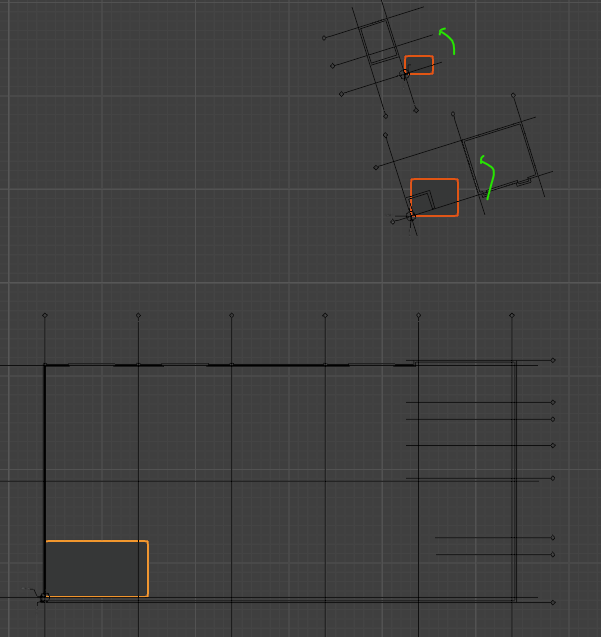
I managed to place the buildings at the right location using Georeferencing but can't figure out how to apply rotation when linked together, I know the angle between Y-axis and true north (see georeferenced DXF attached) which correctly reflects in the settings once entered
DXF:
BBIM:
but once I link the dummy slabs they are not rotated accordingly.
Result:
any advice please?
thanks
I attach the dxf in UTM30N, please change the .txt of file
georef.txtto .dxf, and the 3 dummy .ifc slab elements (their size is different in the real model)I would be available, but ... I have not tested the angle at all, offset only ATM. I just wanted to be sure to know how things work if there is a offset only. Since we have projects with angle as well the topic is highly interested as for me too.
my personal opinion ...
We did not define angles, others in the project did. I would never ever define an angle, never ever never. IMHO the only advantage of angle is problems, problems, problems.
Anyway since we have them I need to deals with them. I will have a look at the last post and the data
sounds scary.. ;-)
the convenience of rotating for me is to be able to operate starting from a classic horizontal - vertical gridline arrangement in the design of a building, with its origin at 0,0
thanks for your assistance
this is what most people tell me if you ask them. But what we do if we are able to decie the orgin of a project. We just turn the CAD not the data. The disadvantage is you need to turn it often. Once the CAD and once again if you put your cuts on the drawing, you need to turn every cut on the drawing because before you only turned the CAD and not the data. Difficault to explain. I fail to explain this to others in German regularly.
jm2c: The problem I see is if the rotation is defined by an angle. It seams Revit has to define an angle. They do not allow it by 3 points, which would be ok. Iven if you define 10 diggits, you can get problems. We have a 500 m long building, if you turn the data really by 3 points and turn it back by the angle with 10 diggits, you get differences on points 750 m away from the origin. Just very small differences, but these differences make your lines are not 100 % parallel or not 100 % 90 degree and so on. The problem is the mixture of the correct rotation defined by 3 points and the rotation by the angle with 10 diggits. If all only use the "wrong" rotation with 10 diggits everything is fine as well.
I have no idea what BlenderBIM does ... not yet ...
interesting take, I didn't think about this
sure, for long/large structures the number of decimals matter a lot for a roundtrip approach.
In my case the offset+rotation is not to create construction drawings, they work in local with a couple of reference points using both systems (WCS/UCS in Autocad terms) since you want to use geographical coordinates to peg the important corners (foundations, mostly) but use local coordinates within the building for instance.
In practical terms the general layout is geroreferenced, the setting out drawings (foundations, alignment, etc) show their geo-coordinates but the structures DWG like plan, elevations and sections, have local dimensioning in a gridline, not geo-coordinates.
In the end I found out how to use offset/rotation using OffsetObjectPlacements patch, which does a good job for me, so happy ending :)
great :-)
would it be possible to edit your post where you described the problems you had in the regard what was needed to get rid of the problem ...
As said, for sure I will have to deal with angles as well in BlenderBIM.
hi @bernd
not entirely sure I understand your request, sorry
my problem was to be able to put together models (railway sheds) created separately on a grid with 0,0 coordinates on their A/1 that could slot in a bigger model (terminal yard) based on their relevant arrangement
Instead of using geo coordinates of those buildings I used their offset values (and rotation) relative to a datum point in the main model and run the
OffsetObjectPlacementpatch.With
LinkI was able to put them together (general plan and buildings) quite well, offsets and rotation were nicely applied.The main model/plan comes from a geo-referenced DWG I offset to 0,0 on the point I used for the offset with the buildings.
Hopefully the above makes sense somehow
Cheers