

Scan to BIM, for real - with IFC?

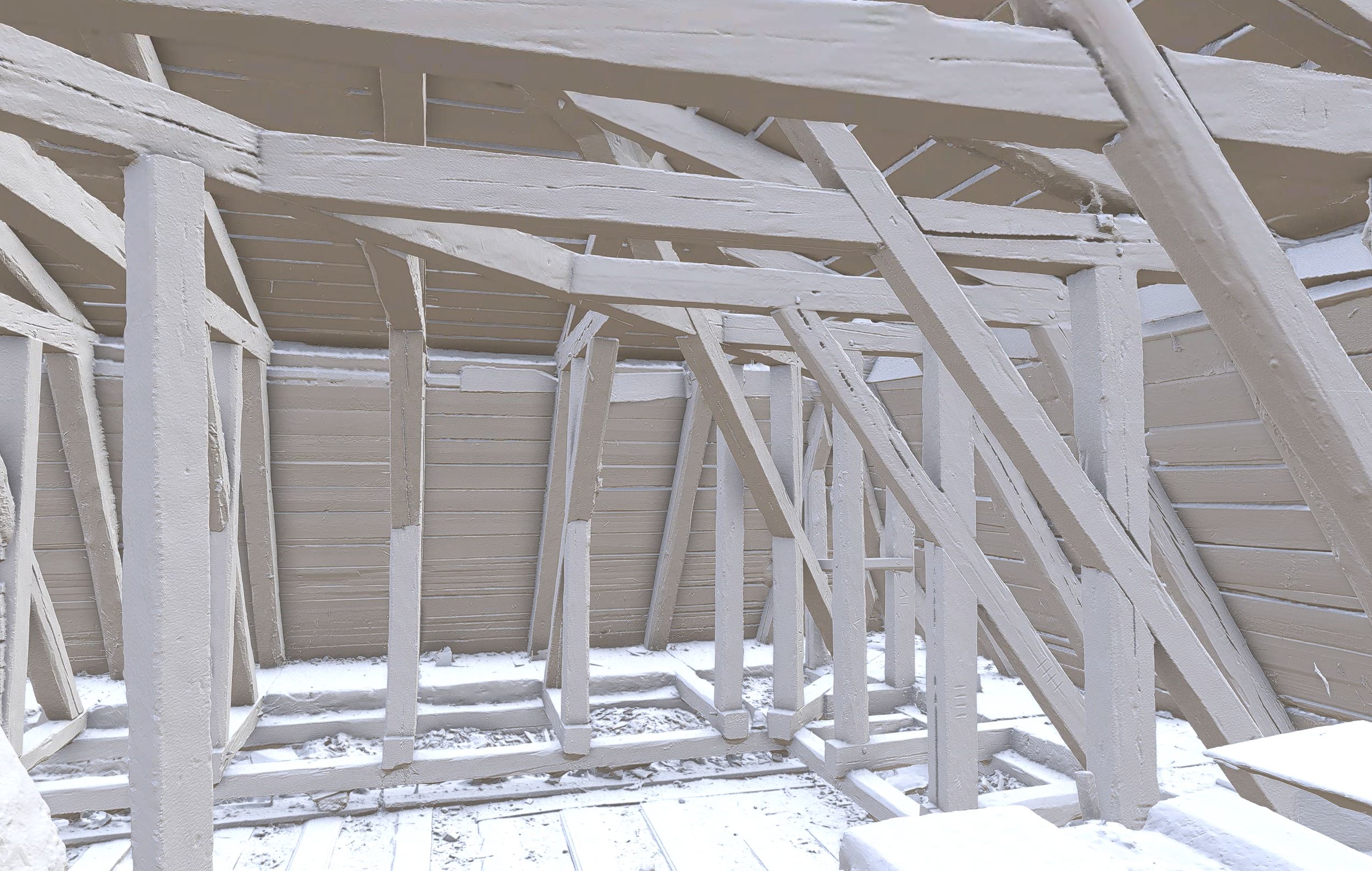
I do scanning of heritage buildings and it is painful to see how a millimetre precision scan gets modeled with decimeter errors into a flat, right angled, perfectly plumb and even thickness wall in BIM software. That is not how they look.
I have tried to cut up a mesh and assign IFC classes to the parts, but it really struggles with big meshes. In vanilla Blender I can handle 100 million polys with acceptable lag, but converting to IFC crashes already at 10 million.
I can simplify them a lot of course but then I also loose detail.
How to approach this? Is the IFC inherently bad at mesh, or is there a way to fix that? Should I detach the mesh from the IFC in some way instead? Other suggestions?


Comments
Could I ask what you process is for the scan to mesh?
A point cloud from a laser scan, then you import as an obj into Blender? and then begin converting to Ifc?
Would it not be possible to use IfcOpenShell directly to make an IFC without first going into Blender?
I haven't used IfcOpenShell myself but taking out the Obj process might speed things up
From my experience IFC and more broadly, AEC programs are not tailored for defining existing building with precision. AFAIK in REVIT, Archicad and Blender's Archipack addon you can't define a regular wall with varying width. I think your desired workflow here if you want to preserve data integrity is not to define the geometry inside the IFC file but to use a link to a model you'll share alongside with it, and open with a dedicated 3D modeling program, not a CAD authoring tool. Until we get quantum computers I don't think architects and engineers will accept to work with millions of polygons for a simple beam. :)
I've been scratching my head at this problem for a while, too so I'd really like any workflow improvement exploration :)
In theory what you're doing could work, but in practice there are some problems:
In my opinion, this is not IFC's problem to solve. IFC should focus on what it does best - semantics for the AEC industry... where semantics overlap with geometry, IFC may get involved (e.g. parametric I-beams, profile cardinality, parametric layered materials and extrusions), but high poly meshes is definitely not semantic and sounds very much like the domain of the CG / scanning world. I would propose merely recording simple forms (perhaps highly decimated) and then referencing an external file for the high-res mesh.
However, these "low res proxies linking to high res external sources" is merely my own theory, and is not officially part of the schema (though maybe in the future it may be?). It's what I did for things like Radiance support which had similar issues, and for things like CG viz and grass blade instances. If you go this route, use an external library reference relationship.
For my Radiance examples, I stored the meshes as OBJ, but since it's an unofficial convention, do what you want ;)
First my process: I combine laser scans and photogrammetry in RealityCapture to produce a textured mesh. I then import it to Blender to cut it up. I usually just separate the rooms to give the customer the possibility to open one room at a time. That way they don't need a beefy computer and it's easier to look at that room with backface culling and nothing else in the way.
For me pointclouds are just a step in the process and not useful for anything but some calculations. They are horrible to navigate as they have no real surface, update as you go, and no backface culling.
My goal is to segment all the parts. Walls, floors. beams etc. and also be able to add information like salt problems in masonry, sensor readings, rot and so on as separate geometry. As well as all the usual maintanance intervall and so on.
I thought .ifc was more agnostic to geometry and able to handle meshes without transforming them to Brep. And I am unfortunately not the guy to write code to get it to work with workarounds. What I may be able to do is get funding so one of you guys can do it, if you think it's worth. I can imagine also architects could enjoy not being limited to Brep.
Just saw the interview with Thomas Krijnen on BIMvoice and he mentioned he had actually worked on integrating mesh, and was almost there. Is he on here under some pseodonym?
@aothms , sorry Thomas. ;) Great interview, btw. :)
I think that's @aothms ?
It is, it can handle tessellations, yet still runs into the two issues I described above. I guess one option is to try and overcome the two issues via HDF5 and a dedicated mesh parser, and the second option is to only use IFC for semantics and develop a convention for referencing externally defined high-res meshes (e.g. via OBJ, glB, or other open data standard) which can be proposed to buildingSMART for IFC5 (but backwards compatible).
The latter sounds easier to me :)
Hey guys, immensely interesting subject. The IFC-HDF5 work we did was also for cultural heritage documentation. We opted for the approach of a regular bim model and then storing the point cloud segments as offsets to those surfaces. We focussed only on the semantic storage and retrieval efficiency. We just assumed a handmodelled IFC model exist that corresponds to the point cloud. What was nice about this was that the compression we got from storing the points as offsets also made the combination of these two so semantically interesting.
Yes, in the talk with Petru from Bimvoice I indeed mentioned the work I have been doing for a couple of years already on being able to select alternative geometry libraries. That would indeed eliminate the BRep reconstruction as highlighted by @Moult. HDF5 could indeed eliminate the difficulties with storing large arrays as textual formats. But even if both were production ready it's still not really realistic to efficiently perform realtime modifications on them. Isolating mesh or point cloud segments into new representations for elements still means move ridiculous amounts of data around that neither HDF5 nor IFC schema is intended for.
Most efficient would be to store the mesh as a monolithic array and rather use something like vertex groups or a separate channel of data to store the association to building element ids. So that you edit by changing values and not structure. And then indeed a way to reference that from IFC or periodically bake this into an IFC file. In HDF5 something like this would be possible by using Region references so that entity instance attribute values would actually be subsets of this monolithic array. Blender and HDF5 both have good interfaces with numpy, so there might be something possible.
So if we use vertex groups for example and link that to the IFC schema, Would that be readable (in a longer perspective) in other software, or never leave BlenderBIM? And what happens if you make a door in this vertexgroup?
For me to be able to get funding it needs to work outside BlenderBIM. Perhaps not immediately, but eventually, and have a chance of becoming a standard.
How much time and money (very, very roughly) are we talking about?
To make this work in other software, it would need to be a project supported by buildingSMART. It would definitely not be immediate. Maybe @berlotti might know if it's of interest?
Ok, also note that I was talking solely about efficiency. My approach collides with BlenderBIM's native IFC editing because of the non-standard way of relating mesh segments to elements. And also it might not be what you want from a usability perspective, because when you hide all this information in mesh channels there's a lot of Blender navigation functionality that doesn't work anymore (e.g conveniently hiding objects by type or sth).
It was just a thought I had that even if you do HDF5, moving around large mesh subsets from one instance to the other is going to be painful because HDF5 statically arranges the datasets and doesn't "vacuum" empty space. Hence my thoughts on creating region references into a monolithic array and trying to see if there is an equivalent for that in Blender. So again, solely thinking from performance, I was hoping for some refinement on this idea in the thread maybe with ideas thinking more from the viewpoint of UX.
To me this sounds more like a EU-funded project or sth. Heritage and digitalization are always topics on the agenda. The RWTH design computation group has done some could heritage and ifc related things and they know blenderbim and I know Duncan has brought up EU-funded projects earlier. This might be the thing.
There would definitely be interest. Biggest challenge will probably be to define a clear objective, scope, intended outcome, etc. Happy to help!
Just speculating here, what if a "perfect" geometry was stored (i.e. the typical parametric extruded beam prism) but alongside it was referenced raw textures which represented offset from the base surface of the perfect geometry. No need to load 2 billion points, can in theory scale very, very easily (just zoom into interested area, inspect texture as displacement map where necessary. Algorithms that were mixed between human intervention and AABB/OBB generation could be used to rapidly create this proxy perfect surface.
We could probably cook up a prototype in Blender within a week or so, reusing Blender's XYZ map baking abilities.
At CNPA EPFL we are also really interested in this topic for HBIM ; we could do some tests if you develop prototypes.
I would point that :
-To produce high quality photomesh models becomes more and more easy and accessible.
-As Blender is perfect to work on the mesh, it would be a great process to classify the photomesh in IFC with BlenderBIM.
-It also becomes easy to share such a work with three.js and IFC.js
I am also interested to see how we could classify a Pointcloud in IFC.
In our work we proposed three methods:
https://pure.tue.nl/ws/files/119667686/20190402_Krijnen.pdf
What @Moult describes is basically the third level. Maybe indeed using textures is a nice middle ground between semantics and ease of use in Blender. You'd obviously need to use some psets or sth to map the [0,255] range onto the physical range of deviations. But essentially this is exactly what we did, we also quantized the point cloud deviations for compression. In the end we just had a little semantic structure to store the deviations, but you could easily opt for storing them as textures.
You'd run in to the limitations of IFC and textures though, especially for extrusions there is very little control over the UV coords, so you'd likely end up with extremely non-uniform texture resolution. So maybe you'd make different choices there, e.g probably not to use extrusions. Or use the schema extension when writing IFC and keep the textures solely as a way to represent them in Blender.
What we were also interested in is seeing the progression of deviation over time, e.g structural health monitoring. So I think that would also be something to account for that you might have multiple scans associated to the same model. Analyse the deviations as a 2d function and then compute the differences in parameters for these function to assess the rate of change.
Are you suggesting not to use point clouds, but rather photogrammetry? Or what is a photomesh precisely?
Really interesting aothms, thanks.
A photomesh is built on pointclouds, it triangles the points to create surfaces and if you have done your capture through photogrammetry, you can texture these surfaces.
You can have really precise pointclouds through lasergammetry (3d scans), you can then convert it in meshes but not texturize it. Although some scanners as Faro do take also photos to allow you to do it. Or you can mix both techniques with a laser and your own camera, as we did on the first project here : https://enac-cnpa.github.io/IFCjs-Stereotomie/
The fact is softwares like Revit and Archicad let you work really easily on pointclouds, but are really not good at importing huge photomesh to model on it. Blender is, and so BlenderBIM would be really a unique tool, if we beginn to scan to bim from photomesh and not anymore from pointclouds. On photomesh you have more comprehensive infos, think for example to a fresco or joints on a stone assembly.
I say photomesh become accessible because of tools as Scaniverse. An architect now just needs an Ipad, whitout understanding anything of all these process, to create a photomesh and start to work on in Blender.
Thanks for explaining, it's been a while since I worked on this. We indeed had these Faro scanners that give an additional colour channel by internally pairing the point cloud with regular photographs. On the one hand, indeed a mesh is much easier to consume visually, on the other hand, it's also quite a destructive process (not sure how much smoothing is involved) but I guess quite a few points are discarded in order to get a reasonable manifold surface. I don't think Blender is even able to actually display the colour channel on points though so there are definitely quite a few arguments to use mesh. I guess it depends on personal preference, required accuracy, documentation requirements and completeness of scan vs amount of geometric detail.
Circling back to the original questions:
What are we exploring here: multi-year funded project or trying to make some quick progress on the great foss tools that are currently already available. Or both? Maybe we should setup a quick online get together to quickly outline everybody's interests in this topic?
EXR :)
Yes, I actually thought of that, but do you get reasonable colour values when you look at that in the 3d view? That would be even cooler though, maybe there is a live colour map you can slap onto it.
I'm not really sure if point cloud data should make it into an IFC model at all. 3D scans are made several times during construction and operation of a building. What is the geometry of an object then?
I would find it much more helpful if all those scans would be geo referenced and I could grab the relevant portion of the point cloud using my element bounding box. The goal should be clean and efficient geometry to not bloat the ifc file size. Abstraction is king.
@tobenz this depends on the use case though. First of all, what I was saying with HDF5 isn't too far off of what you say, one big dataset with point clouds, and instead of doing a lookup by bounding box, you directly associate point cloud segments to the elements (as the primary representation or supplementary with a timestamp).
More generally (you see this also with IfcTunnel now for example and geotechnical datasets) there is the need to make meaningful semantic connections for documentation purposes, so then you either need to:
The pros and cons of these are fairly obvious, but how you weigh them depends on the use case.
Maybe this guy https://github.com/florentPoux can be useful
Gigantic meshes are a problem of course. Can be solved with LOD (Level of Detail, as in game engine, not the architectural version). I usually make a web version of the mesh with low polycount and Normal maps, and one high poly version for measures, 3d-print and calculations. Clipping box is useful of course as even a low poly royal palace has millions of triangles. We can also hope for Unreal engines Nanite goes open-source and implemented in all 3d sofware (yeah, right).
I am doing a prestudy right now for the National Heritage Board about the implementation of the EU recommendations from 2011, updated 2021, stating that:
"The digital strategy should set clear digitisation and digital preservation goals. Those goals should be based on objective and clear criteria, including:
(a) cultural heritage at risk,
(b) the most physically visited cultural and heritage monuments, buildings and sites and
(c) the low level of digitisation for specific categories of cultural heritage assets.
By 2030, Member States should digitise in 3D all monuments and sites falling under (a) and 50% of those falling under (b).
By 2025, Member States should digitise 40% of the overall 2030 targets.
Member States should take the necessary measures to ensure that all digitised cultural assets referred to in point 6 (a), (b) and (c) are also digitally preserved."
This will hopefully lead to a lot of heritage being scanned. It would be a pity if those scans just rotted away on a harddrive somewhere and only were used in case of destruction of the monument. They should be used for visualisations for the public and also BIM models for the administration. But seeing all these wonderful buildings as Revit cardboard boxes will break my heart.
So there is potential for big money, but I can only affect little Sweden and would need help from you others. If we can set a goal, a way there, an estimated budget and timeschedule, it will be a lot easier to get funding. Do you think it is possible in a few years perspective?
I am also aware of an Australian NSW initiative to scan every single heritage sandstone building here (though I heard they had funding heavily cut) but perhaps I can help reach out to some Australian contacts here and make a connection if you'd like to take the lead?
@Hagaeus here in Denmark we have Molio which might be well suited to taking the lead on an initiative like this. Is there anything similar in Sweden?
@duncan I think that would be the equivalent of Boverket. I actually talked to a guy there this week who was interested in a co-operation regarding other stuff. That is a great idea as they are under the finance department and therefore have money, unlike the Heritage board that is under the Culture department.
@Moult I could do that next year if I get some support from others. I am a one man company with the workload for two, plus admin, right now. Getting support from Australia would show that it is of international interest as well. I guess you are the one for lobbying towards BuildingSmart? Or does anyone else have good connections there?
Hey @Hagaeus
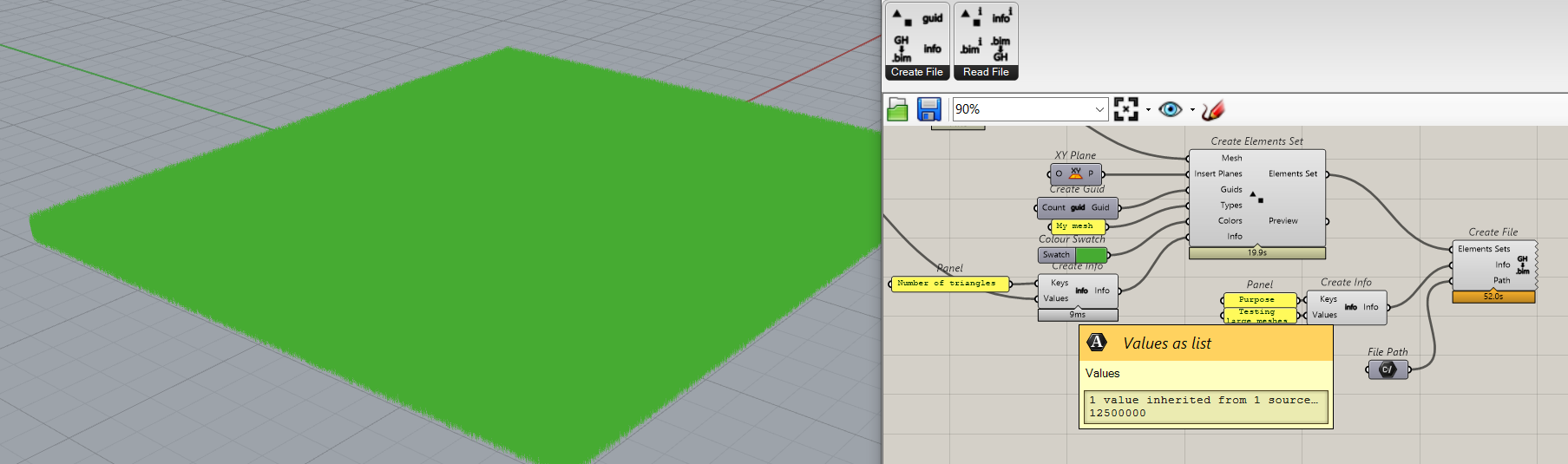
it would be interesting if you could try out using .bim file format for that (https://dotbim.net/), and let me know the results.
For tests I created a mesh with 12 500 000 triangles in Grasshopper. I attached some custom data to it and exported it as .bim. It took as you can see below 52 seconds to save that file, and it is 1.13 GB big. After simple ZIP it reduced the size to 140 MB. There is still room for improvement there (removing white spaces, removing unnecessary decimal numbers, quality of mesh).
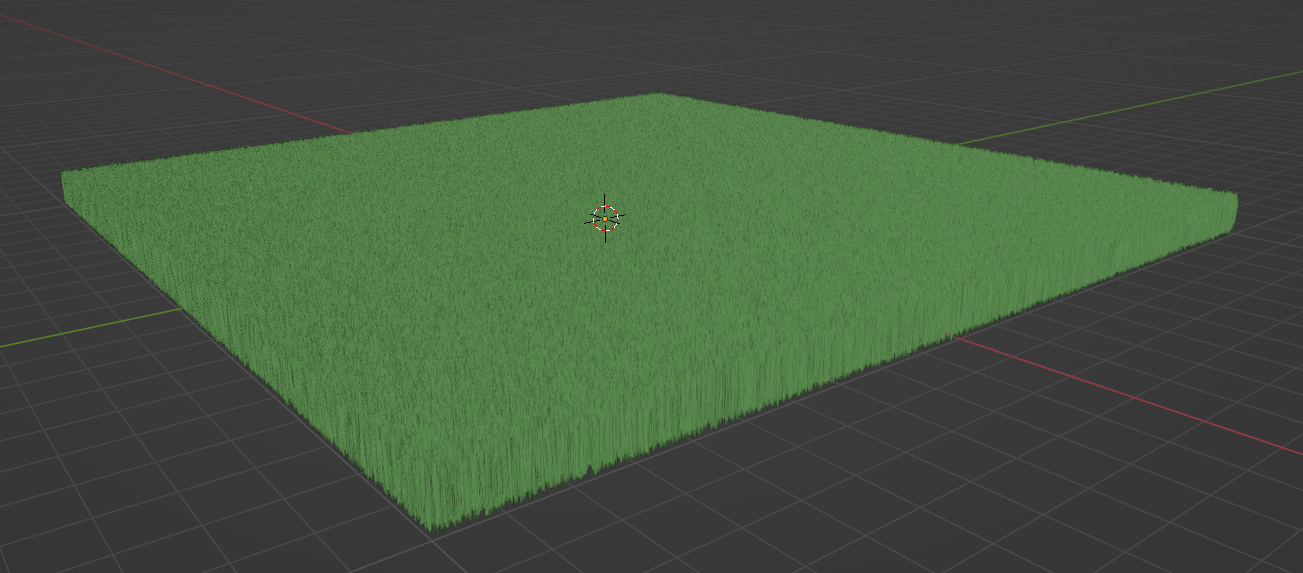
Then I imported it to Blender and it works fine:
Regarding having a giant meshes in a model and LOD, one of the ideas was to actually store different LODs in separate models and link them together, rather than having it all in one giantic model / file. Not sure if such concept would be interesting for scans, but you can also check it out there and let me know what you think: https://github.com/paireks/dotbim/blob/master/LinkingData.md
I completely understand your frustration! Losing precious detail from high-precision scans due to limitations in BIM software is definitely painful. Here are some thoughts and potential approaches.
Understanding the Challenge:
IFC limitations While IFC supports meshes, large and complex ones can indeed cause issues. Some software might have better handling than others, so investigating alternatives could be worthwhile.
Software optimization Check if your BIM software offers any settings or plugins specifically designed for handling large meshes efficiently. Sometimes tweaking mesh decimation algorithms or using lower-precision representations for less critical details can help.
Data reduction strategies Explore options like simplifying specific areas while preserving high detail in crucial parts. Consider using LOD (Level of Detail) techniques to manage complexity depending on the viewing distance and purpose of the model.
This looks like something spat out of chatGPT, did you mean to add something specific to the conversation ? :)