

Can Bonsai BIM be used for doing Cost Work Estimation for Skate Parks?

I have a friend, who exclusively works on designing Skate Parks and I have literally zero knowledge about skate parks. However, he is looking for a CAD software that makes it easy not just design skate parks, but also so that he can estimate the areas and volumes involved. The primary difference between skate parks and regular buildings is that skate parks involve a lot of curves and I am not aware whether Bonsai has curved wall elements or not. So any help this community can provide will be greatly helpful to me and my friend. Thank you.
Tagged:
Comments
Hi @lokitkhemka even though Bonsai is a BIM authoring tool you are not limited to using BIM walls, slabs etc you can mesh model with Blender and then assign Ifc Classes, materials, coverings etc to those meshes. From there you can do quantity takeoffs.
Awesome. Thank you so much.
delete the .txt
BIG caveat: I have never designed a skate park either, I do own a couple of pairs of Vans though ;)
forgot the Ifc, Search for @steverugi on this forum, he is the master (calls himself an apprentice) of getting quantities out of Bonsai
@lokitkhemka
as @Nigel said
it can be done, but it might be something not straightforward for non-regular sections like the one beautifully designed above.
I searched online and an example like this:
could be a challenge to model and make sure to be consistent with the components of your project (walls, slabs, backfill, under layer, top layer, etc).
Meaning that you don't have regular (prismatic) solids where the volume is simply a constant cross section area * extruded length.
I haven't verified quantities of complex solids like that in my working experience so it's a bit of gray area for me, but I can speculate if you will.
Maybe using a TIN (the top surface as a triangualated mesh) calculation, I did something in the past using CloudCompare but, to be honest, it was some time ago.
In summary:
Any idea as to how those parks are built? Now I'm curious to know ;)
Please advise
@steverugi Thank you for the detailed explanation. My friend does it, so I don't know the details. From my understanding, how he currently approaches it is that he designs them in Autodesk Max and then computes the volumes and areas involved by hand. I have been following Bonsai for a long time and I was fairly aware that computing quantities were an important part of BIM calculations, due to my Civil Engineering background. So, I suggested Blender and Bonsai to me.
For volume calculations, sampling z-values could be the way to go and then applying some integration rule. Pretty sure, tolerance will be more than acceptable.
Will update more on this thread, if and when I find more information.
P.S. this forum is perhaps one of the most fun interactions I have had online. Thank you so much for this.
Hmmm. How about just making your mesh, converting it to an IfcSlab, and running the Qto on it. Example:
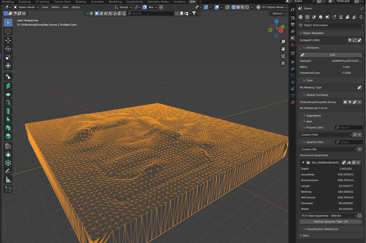
yes of course, my point in the previous post is that I haven't checked the quality of complex mesh/solids but hopefully this is the correct one
I would use IfcEarthworksFill instead of IfcSlab 8)
cheers
@steverugi Yeah, I defer to you on the proper classification. I was just trying to point out that doing math is what the computers for! 😉 @lokitkhemka was talking like he was ready to break out pencil, paper and a slide rule.