

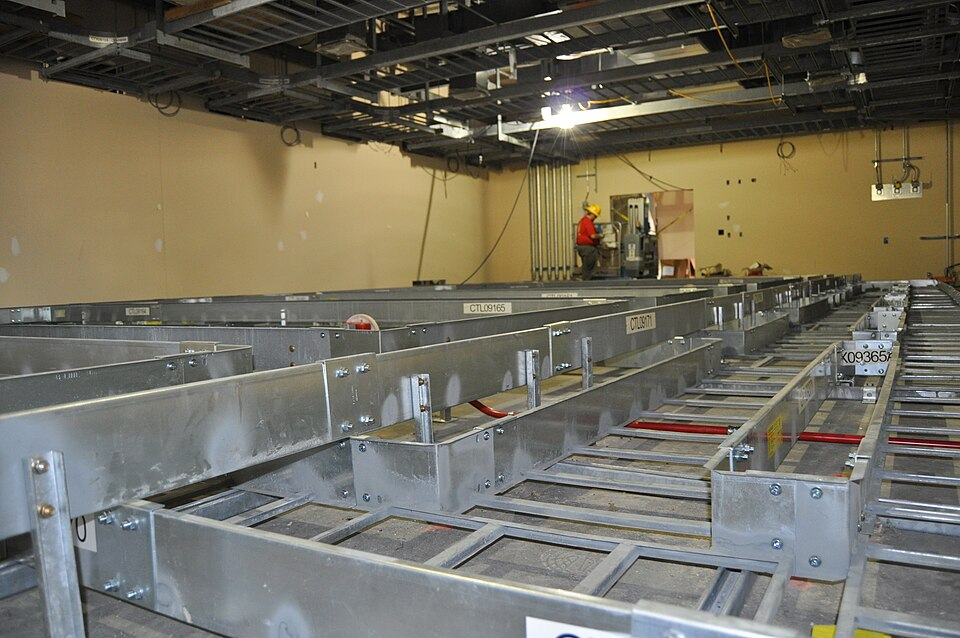
What is a good way to model ladder rungs?

What would be a good profile definition for ladder rungs?
.jpg)
Side rails can be defined using IfcIShapeProfileDef or IfcCShapeProfileDef, and extruded into straight lines using IfcExtrudedAreaSolid. Bends can be defined using IfcRevolvedAreaSolid.
The rungs are flat rectangles spaced evenly between the side rails. Should I first prepare a uniform flat plate and then create voids in it to form the ladder shape?
How does the IFC Modeller create the ladder shape? Please advise.

Comments
Surely the "information" part in BIM would suggest that if you want to get quantities out of your model (i.e. X meters of profile A, Y meters of profile B) then logically you want to use the method that can give you that information. A voided plate will not give that.
@sjb007
if the rungs have the same regular profile, you can derive the length from the voided area.
@KoAra can you share a sample with dimensions?
Just speculating here (I rarely do electrical stuff), I would personally work on the linear meters of the cable ladder and derive all quantities from one "module" since rungs and profiles are constant, plus bends per piece.
Thank you for your reply :)
@steverugi
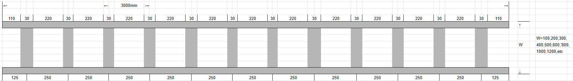
In my country, the standard length is 3000 mm, and the spacing between rungs is 250 mm or less.
At a certain manufacturing company, there is initially a 110 mm void. Next, there is a 30 mm rung, followed by a 220 mm void, and then another 30 mm rung. This pattern repeats itself, ending with a 110 mm void. It may be better to think of it as a repetition of 110 mm voids, 30 mm rungs, and 110 mm voids.
@KoAra
something like this?
you can set the width adjusting the depth value
for the quantity, as you suggested, you can sample the pattern 110+30+110 and extract it based on the length of the extruded side (I kind of guessed its dims in my simple model)
but if you want to check the length of the rung "array" there is a manual option as shown here:
2780-30 = 2750/(220+30) = 11+1 = 12 * length of rung
there is also the actual array option but IMHO it could be a bit tedious to handle
I also played around a little bit. Modeled the CarrierSegment in a classic Blender way. (Array, Solidify, Join ---> Hint: Always apply the Scale, Set the Origin,,... Apply an ifcType.... (Qto-Length is "auto" Width is a Custom Qto, didn´t modelled it exactly). Result SegmentType with geometry 3000mm... PassLength shouldn´t be tricky, but I wouln´t create for every part an ifcType, just objects with the right class and a "speaking Names". CableCarrierPasslengthxyzmm or something in that way....
IfcFile is attached.
Tried also the way with Profiles, after joining all together and reclassifying the object as a Type, I got errors. When Iam modeling fences or railings with profiles, it´s always tricky with adding new Profiles, copying, change Length, rotate....). Maybe I should check out the "external parametric Geometry" tool....
Hope it helps to find the right modelingsolution....
@steverugi
Thank you for your reply and for creating the IFC. I read IFC in text form.
You define multiple swept areas in IfcCompositeProfileDef and then extrude them. This is very helpful.
On the drawings, they are arranged like pipes or duct segments, without being restricted to 3m lengths, so I will consider a better method.
@Mas
Thank you for your reply.
The details of your IFC model are beautiful. However, you have defined many polygonal faces. It seems that the longer the cable carrier ladder is, the larger the file size will be.
Would it be okay to place a cable carrier ladder?
@KoAra Your are absolute right, its a part with polygonal faces... more detail means more faces