

Saikei Civil — Native IFC for Horizontal Construction

Hey everyone! I'm excited to share a project I've been working on: Saikei Civil — an open-source civil engineering design platform built on Blender with native IFC authoring.
After discovering Bonsai, I've been deeply inspired by what's been accomplished. I see massive potential for greater implementation of BIM and digital twins of infrastructure based on IFC models. Today, the primary tools for building those models cost thousands of dollars per year and only create IFC through export — a clunky process often fraught with errors and lost data. Bonsai is tackling these issues in vertical construction beautifully.
Enter Saikei. While reading through the community archives about the BlenderBIM → Bonsai transition, I was struck by how perfectly "Bonsai" captures the essence of detailed, crafted building design. For civil/horizontal infrastructure, I chose "Saikei" (栽景, pronounced "sigh-kay") — the Japanese art of creating miniature landscapes. While bonsai focuses on a single tree, saikei encompasses terrain, paths, water features, and complete scenes. It's the natural complement:
• Bonsai = Vertical (buildings, architecture)
• Saikei = Horizontal (roads, grading, drainage, infrastructure)
What's Working Today
The project is in active development, with a focus on roadway design:
• ✅ Native IFC 4.3 alignment creation (IfcAlignment, IfcAlignmentHorizontal, IfcAlignmentVertical)
• ✅ PI-based horizontal design with automatic tangent/curve generation
• ✅ PVI-based vertical profiles with parabolic curves
What's Under Construction
• 🚧 Georeferencing with 6,000+ CRS support via PyProj (sub-mm precision)
• 🏗️ Cross-section assemblies with AASHTO-compliant templates
• 🔧 Parametric "Point Control" constraints based on stationing/chainage
• 🛠️ 3D corridor visualization, completely in IFC objects
• 📐 ~25,000 lines of code, 107+ tests passing
The Goal
Civil 3D and OpenRoads cost $5–10K/year. We're building a professional-grade alternative that's:
• 100% open source
• Native IFC (not export-based)
• Built on Blender + IfcOpenShell
• Accessible to small firms, students, and engineers worldwide
Links
🔗 GitHub: https://github.com/saikeicivil/SaikeiCivil/tree/main
🌐 Website: https://saikeicivil.org (coming soon)
I'd love feedback, contributions, and collaboration — particularly from anyone working on IFC 4.3 infrastructure schemas or Bonsai integration. This is my passion project and has become my full-time focus. I believe in this.
"Saikei: Cultivating Open Infrastructure"
— Michael Yoder, Desert Springs Civil Engineering PLLC


 and 4 others.
Comments
It looks very promising. Will it allow geometry nodes to be used with it?
Great question! I'm not sure yet, but if I do use geometry nodes, it will primarily be just for previews. The actual corridor modeling will be more code driven, Python + BMesh on the backend, with a viewer/GUI for editing. From what I can tell, this is more how the Civil 3D's and OpenRoad's programs work. I'm attaching a markdown summary I made to document the decision on that. Ignore the "sprint" language, I've been using Claude AI to organize which aspects I work on first :)
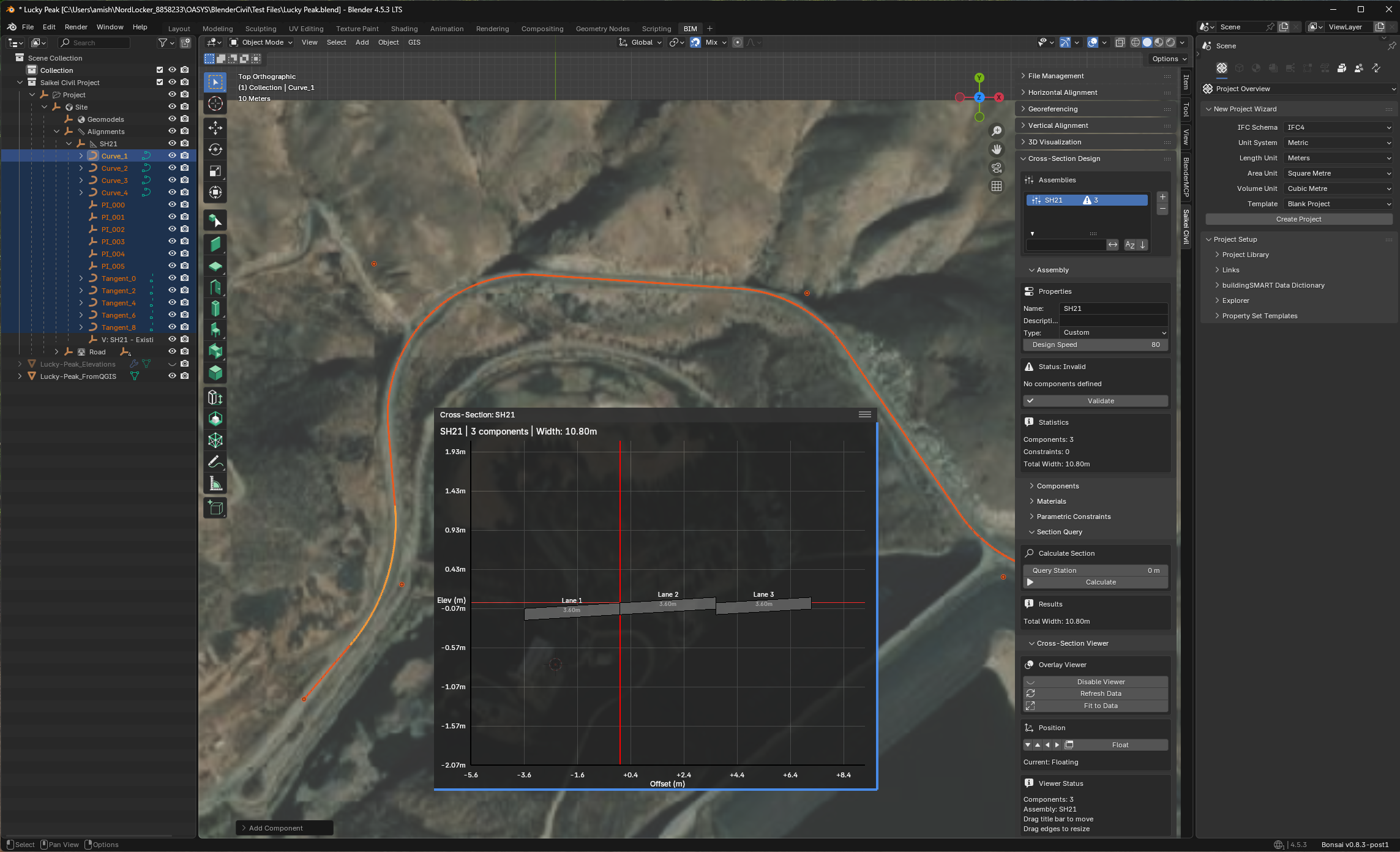
Here's a screenshot of what I have for the cross section viewer right now. Definitely still needs work, and corridor generation will be after that.
All that said: I am wide open to ideas, suggestions, criticism, etc. I want to get as much input as possible while I'm building this!
Ping @Rick_Brice @civilx64
Hi @myoder89
would you be available for a video call to showcase your add-on? it can be recorded and shared here
I am hoping to involve my colleague Jonathan (rail/road engineer), he too made some steps with Blender for alignment plan/profile in the past
Cheers
That's some fantastic initiative! I'm certainly following on this. You might want to check the (maybe mix) with BlenderGIS initiatives already in place. BlenderGIS can be used for earial photography and gis data for civil3D. As a matter of fact i am still looking for someone who can rearrage the behaviour of BlenderGIS offsettting the origine of IFC4 georeferenced **. Mapconversion is skewed up when working togetter. Uses of BlenderGIS for Civil could be in scope as well.
** this video and post
https://community.osarch.org/discussion/3226/blendergis-changes-ifc-positioning
I'd be happy to do a video call! We can work out the details of private message if that works for you.
Absolutely, I have BlenderGIS installed now and I'm using it to import GeoTIFFs into Blender so that i can have aerials and terrain data for now. I am working on a georeferencing module, but it will likely also rely on some version of the offset or "false" origin method.
I did read the post you linked to- I'm not sure I completely understand the issue, but I think what you're seeing is an issue that Blender itself has dealing with very large values. I found decent explanations at these sites regarding this Float32 issue:
https://github.com/domlysz/BlenderGIS/wiki/Georeferencing-management
https://blender.stackexchange.com/questions/336286/from-gis-to-blender-using-sensible-coordinates
I also found a very helpful video demonstrating workflows to help get around some of these problems by creating custom projections through QGIS:
https://blender.stackexchange.com/questions/336286/from-gis-to-blender-using-sensible-coordinates
Hey all, just posting an update on the Saikei effort to develop native IFC4.3 civil infrastructure modeling. Currently, with great help from @Dion, we are working on merging the Saikei tools into Bonsai. As part of that effort, I would like to have an open discussion with the community on UI decisions, and where the appropriate “home” should be for these tools.
First, a quick shoutout to Thomas @aothms, Scott @civilx64 , Rick @Rick_Brice , Jonathan @Frans , and Dion @dionmoult , who in previous conversations over the past year or so have provided a solid base for this effort. Thank you all!
From those past efforts, a general workflow for infrastructure authoring has been established, and I’ve written my own summary of that below. While infrastructure covers a great deal of workflows, because my background and current work is roadway engineering, I will use roadway workflow as an example. Many of the concepts though will be applicable to other disciplines (utilities, bridges, rail, tunnels, etc.)
Currently, there are existing Bonsai tools that I think are capable of supporting the work of sections 1 & 4. Georeferencing exists under the Project Overview tab, and I believe the tools in the “Drawings and Documents” tab will be sufficient for supporting the drawing work. The Sections in bold, Authoring and Analysis, are where we are in new territory.
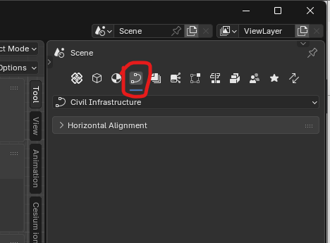
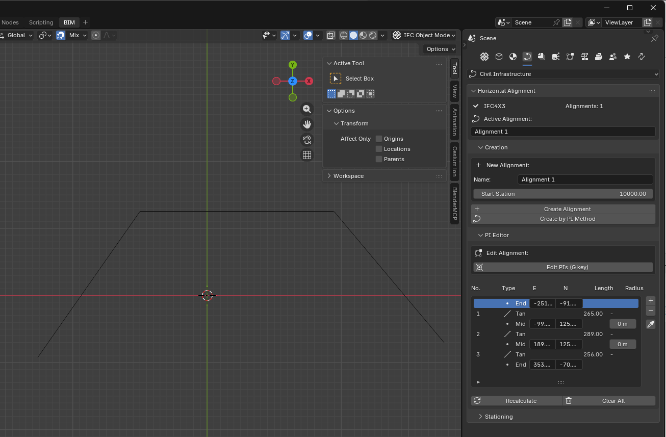
To date, I’ve built a Civil Infrastructure tab to be added to the scene properties sidebar, and added a submenu for Horizontal Alignment authoring via the PI method (see screenshots below):
This is where you all come in:** Is this the right place in Bonsai for the Civil Infrastructure tools? What suggestions does anyone have in regards to location/layout within Blender?** Ultimately, these are important questions for overall flow of using Bonsai, so I wanted to open this conversation up to everyone before we plow too much further ahead. Also, I'm happy to discuss the different submenus that I would expect in this new tab, but figured I'd get the overall question out there first. Thanks all!
@myoder89 excellent work.
You have inspired me to think about this more carefully. Here is an unfiltered braindump of things to consider.
UI Tab
The Civil Infrastructure tab seems to be the right place for this, though Alignments might be a better name. Civil Infrastructure is very broad. At some point I can envision being able to model catch basins, traffic signs and signals, retaining walls, lane striping, underground utilities, and all the other stuff that makes up Civil Infrastructure.
On the tab, there is an input group for Horizontal Alignment. I can envision adding Vertical Alignment and Cant Alignment groups in the future. This is a logical grouping.
Presentation of Alignment
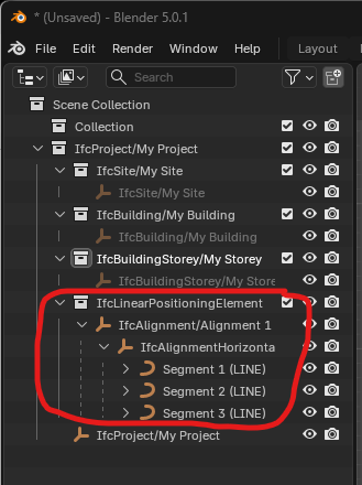
In the Scene Collection pane, I like the way each individual segment is broken out under IfcAlignmentHorizontal. Currently when opening a file with IfcAlignment there isn't such a breakout.
Interactive creation of horizontal alignment
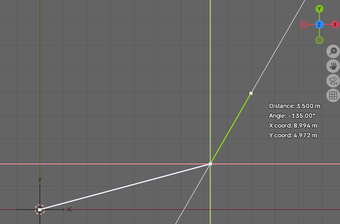
The feature to draw out the alignment tangents and define PIs is very nice.
I would recommend the following improvements:
1. For the Angle, also show Bearing of the line; e.g N 30 15 24 E. That's how we civil engineers think.
2. Allow for manual input of Distance and one of Bearing, Angle, Deflection Angle. Probably with a pop-up input box.
3. Interactively define the smoothing curves before ending the command. The steps would be something like those listed next.
Steps for defining a horizontal alignment interactively
1. Press eyedropper (or something similar) to begin command
2. Rotate 3D viewport to the XY plane (Z-up)
3. Using the mouse, draw the tangent lines with the mouse or the text input described above
4. Repeat #3 until all tangents are drawn
5. Right click (or something else, whatever is standard) to signal you are moving onto the second phase of the command
6. Click on each PI (or only the PIs you want) and input the smoothing type and parameters. Examples of smoothing type would be Circular, Spiral-Circular, Circular-Spiral, or Spiral-Circular-Spiral.
7. In a pop-up (or other appropriate UI element) input the parameters. For Circular curve, the input is simply radius. For Spiral curve, the input is spiral type (Clothoid, Bloss, Cosine, Helmert, etc.) and the spiral length. Though this assumes all spirals have an infinite radius and the same radius as the circular arc. There are other uses cases, like a spiral between two circular arcs of different radius (Spiral-Circular-Spiral-Circular-Spiral). I'm not sure what a UI would be for something like that maybe need to select 2-PIs and then define all the parameters.
8. Right click (or whatever is standard) to single the end of the command. Automatically generate the alignment.
Interrogating an Alignment
The grid of PIs could change to just some basic information about the alignment layout. PI points wouldn't be needed. With each alignment segment in the Scene Collection, you could select a segment and it could be highlighted and information like Start Point, End Point, Length, Radius, PI, Center of Circle, Spiral Type, could be displayed in the 3D viewport. Additionally, tangent and radial lines could be drawn.
Interactively Editing Alignment
Two scenarios come to mind; moving a Start/PI/End point and changing smoothing curve parameters.
In the first scenario, you select the alignment Start Point, End Point, or a PI point and drag it (or key in) a new position.
In the second scenario, you select a smoothing curve and you get the same UI element used to define the smoothing curve. Parameters can be changed.
For now, we can wipe-out and regenerate. In the future, we can be more selected and re-generate subsets of the alignment.
Let me know how I can help with the back-end API... I'd also like to learn a bit about how the front-end UI works.