

New feature: Edge classification for improving drawing output

So @theoryshaw thought this was worth it's own post.
With the power of Claude and my elite skills, I bring you differentiated rendering of edges in Bonsai drawings. Available in the daily unstable repository now.
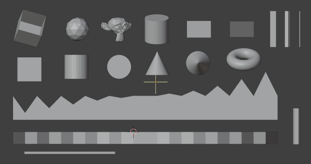
Here's my original test scene with a variety of objects with default SVG:
And here's how the SVG serialiser would convert that into a drawing:

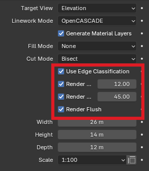
Using the following new settings (per drawing, defaults to old method):
This now turns into (note that this is using exaggerated colours for explanation):
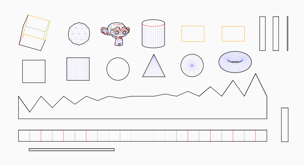
These lines' styling is set in CSS. Just look for the following:
path.outline(black): What you would expect, including where an object overlaps itself.path.boundary(orange): Where an edge only has one face, instead of two.path.sharp(red): Where an edge forms a ridge, with configurable threshold.path.crease(green): Where an edge forms a valley, also with its own configurable threshold.path.flush(blue): Edges that are between the sharp and crease thresholds, but not coplanar. (off by default)*
Now obviously you don't want bright debugging colours, so here it is with more typical styling choices of weight and opacity. Before:
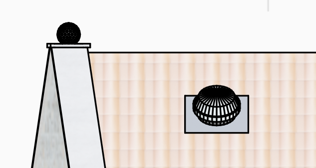
After, flush off:
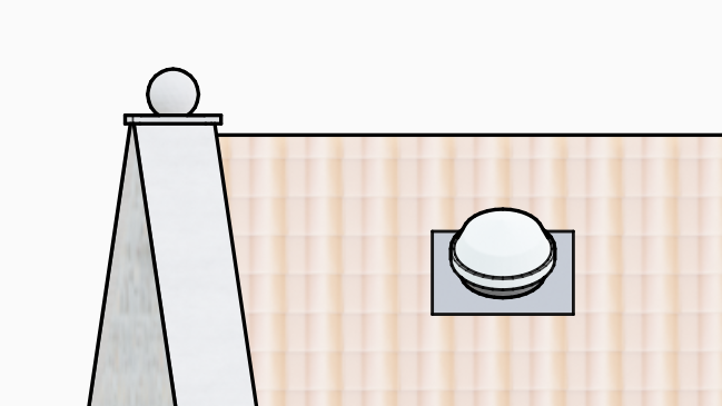
After, flush on:
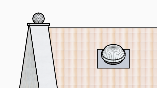
You will need to update your projects own drawings/assets/default.css file to include the new rules, and set them to values that work for you. New projects should inherit from the default included one. Although I haven't tested it, there is no obvious blocker to having IFC Class or Material specific rules, so different styling can be used within a single drawing.
I tested this quite a lot, so I'm hopeful there won't be any glaring cock-ups, but let me know if you encounter issues, and I'll address them. I'd also be interested to see any nice renders using this effect.
Also if people think the current CSS styling is ugly/gauche/child-like, I'm certainly open to better defaults. These are just what the AI came up with, plus a tweak from me.
One last note: The way this works is to add class styling to the individual paths (only way it can work without radically changing the current architecture). This will increase your filesizes to some degree.
Cheers!
More detail than anyone could probably ever want is available here:
Original issue: https://github.com/IfcOpenShell/IfcOpenShell/issues/3668
Pull Request: https://github.com/IfcOpenShell/IfcOpenShell/pull/8608









 and 3 others.
Comments
Yesssss !
Fight against these ugly support Edges of Meshes in AEC ;)
True Solids forever !
Well, I'm surprised myself when I checked the file size question mark:
Old method: 300 kB
Just Outline: 196 kB
Default (no flush): 220 kB
With Flush:324 kB
I thought it'd be much more.
Maybe the majority of file size comes from Fills/Textures (?)
Possibly. I guess I just overestimated what adding class="something" to every "p" tag would add. Happy days!
This is really, really good! A huge thank you for all the incredible work done here.l
Wow. That opens up so much possibilities for me. Thank you. Performance wise did you notice any impact on bigger scenes ?
Does it reliably solve the limitations of the line art modifier regarding inconsistent orthogonal lines and such ?
Can't wait to test this out. Cheers
@Gorgious I didn't notice anything "bad" performance wise, but I don't have any big testcases, and I hadn't actually done a comparison. It's easy enough to test, because not activating the option pretty much identical (maybe one more clock cycle per line on an if expression clause that probably gets optimised out anyway with CPU branch prediction). A comparison on my fairly basic model gives:
Each test run 3x and the middle figure given here.
So I think it's fair to say it is negligible.
On the orthogonal lineart thing, do you mean the thing I pointed out in my responses to you in the original issue? As far as I've seen and used it so far, this nails every line correctly, as I would expect them to be. No strange variance in the line width/categorisation of line. No mysterious lines appearing that might be bleed through from too thin coverings. The corner case of one face being edge-on to camera view and the floating point math flipping between outline and another categorisation is handled, so if it is within a small tolerance it is always classed as outline.
I'll add an addendum... The only thing this doesn't "fix" is the coplanar lines between different objects with the same material. That is a completely different section of code that @theoryshaw came up with. He made amazing progress and got most of it working, but I have a torture case he couldn't get working: an "EXISTING" wall, with a "NEW" plug to fill a removed window ("DEMOLISH") but the walls have the same material. No matter what he couldn't get it to handle that particular issue. So there I see unwanted lines on my model. I was thinking to have a look at that myself later just in case I can come up with a magical Claude prompt. It's either my model (vertices not coincident, although I'm 90% sure they are) or some fantastically complicated code fix.
If curious... https://github.com/IfcOpenShell/IfcOpenShell/pull/7908