This is fantastic work @theoryshaw ! I do need to make some time to improve the native representation support in the BlenderBIM Add-on. By the way, perhaps this is better on the OSArch Wiki? More people can edit, and I expect this to grow to include things like advanced BREPs, IfcAlignment, ParameterisedProfileDef ... I can say for sure that the NSW government body was very interested in results like these ...
Thanks Dion. I personally like keeping this documentation on git, as it allows others to fork, and it keeps the documentation very close to the associated files. I could see, as this evolves, there could be a tighter connection, or even automation between the files and the documentation.
How about creating a OSArch group on Gitlab and forking this FreeMVD repo? I'd be happy to push experiments to that instead. @yorik what's your thoughts?
@yorik said:
... a third test (extrusions of circles and rectangles), which of course BlenderBIM will probably fail, as these entities don't exist in Blender ...
@theoryshaw the depth will be implicitly shown in the object itself. Internally it will be stored - maybe it should be exposed hmm :)
Blender's extrusion modifiers (solidify, or curve extrude) only extrude normal to the plane. This is not sufficient to support the custom extruded direction feature of IFC. Also, an object may include both extrusions and BREPs simultaneously - Blender will be able to handle them, but it means I cannot use modifiers.
Amazing development @Moult !
In any case this is a slippery area, there are many IFC cases that don't translate 1:1 to neither Blender or FreeCAD (or Revit for that matter :D ). But circles are a convenient thing to support since they appear a lot everywhere in buildings and you can usually reduce your filesize by a big factor. Maybe just a kind of "export as circle" switch somewhere would be sufficient? Then you could easily deduce the radius I think, from the center point and one of the vertices
@Moult is the profile exposed too in blender? If not, I feel it should. Otherwise I feel it would be cumbersome to modifiy the profile in blender, as you would have to 'explode' and re-extrude.
Retaining the profile, would also play into accommodating 'mapped profiles' in the future--could tap into libraries like these: https://github.com/OpeningDesign/BIM_Profiles
--
Also, I would say a vast majority of extrusions in AEC are normal to the direction of the profile. Is this one thing we could be strict on? Would this help to develop an implementation where the profile and extrusion distance were exposed in blender?
In any case this is a slippery area, there are many IFC cases that don't translate 1:1 to neither Blender or FreeCAD (or Revit for that matter :D ). But circles are a convenient thing to support since they appear a lot everywhere in buildings and you can usually reduce your filesize by a big factor. Maybe just a kind of "export as circle" switch somewhere would be sufficient? Then you could easily deduce the radius I think, from the center point and one of the vertices
Would extruding a 'Nurb Circle' verses a 'Mesh Circle' be a better approach to emulate a true circle?
@theoryshaw I've considered those options - there are a few downsides to a Blender curves approach (applies both to arbitrary profiles and circles - note that Bezier-based circles are not true circles, they are approximations ... not that the error factor matters though!)
No support for custom extrusion direction
Only support for a single curve, it is possible for an IFC object to have multiple extruded solids in a single object
If you consider a non-rational B-spline (NUBS), then you are correct. However, rational B-splines (NURBS) are designed to represent geometries like a circle, sphere, cone, etc.
@theoryshaw The BlenderBIM Add-on can now round-trip IfcArbitraryClosedProfileDef and IfcRectangleProfileDef :) Will be in next release! Full log here.
Right now, just the functionality is implemented. Usability has still to be debated :) I have a hunch that for most cases, you won't need to inspect the vertex groups at all and just edit it leave it as that... but I won't know until I've used this more on actual projects :)
@Moult said: @theoryshaw I've considered those options - there are a few downsides to a Blender curves approach (applies both to arbitrary profiles and circles - note that Bezier-based circles are not true circles, they are approximations ... not that the error factor matters though!)
No support for custom extrusion direction
Only support for a single curve, it is possible for an IFC object to have multiple extruded solids in a single object
Also pay attention at material indexes, with curves you loose control of "by segment" material id.
Correct, the extrusion directly does not need to be perpendicular. In Blender, this is easy to create - and when it imports into Revit, it actually turns itself into a "sweep" object with two profiles. Will provide a test file soon.
This first file is an example of a non-perpendicular extrusion:
This second file is an example of two extrusions with different distances (though the profiles can change too!) in a single object:
For each, I have produced the extrusion either as a rectangular extrusion, or as an arbitrary closed profile. What I discovered on my Revit 2019 install (please check on yours) is that linking the rectangle extrusions works, but opening the rectangle extrusions do not work. If you open the Revit file generated by the linking process, you get an uneditable object. However, if you open the arbitrary extrusion version, Revit will let you modify both the sloped, and the multiple extrusions. That suggests to me that round-tripping rectangles perhaps isn't a good idea with Revit - what do your tests show?
Thanks, yes that's what I thought you meant by multiple extrusions in a single object.
...
Added your files and some other results in the 'random tests' folder...
...
Yes, rectangular profile does not translate in Revit.
...
A non_perpendicular_extrusion_direction is not translated into Revit upon import--it creates a 'blend' with a top and bottom profile. And upon export, it created a faceted Brep.
...
I plan on creating more official tests for these in the near future.


Comments
This is fantastic work @theoryshaw ! I do need to make some time to improve the native representation support in the BlenderBIM Add-on. By the way, perhaps this is better on the OSArch Wiki? More people can edit, and I expect this to grow to include things like advanced BREPs, IfcAlignment, ParameterisedProfileDef ... I can say for sure that the NSW government body was very interested in results like these ...
Thanks Dion. I personally like keeping this documentation on git, as it allows others to fork, and it keeps the documentation very close to the associated files. I could see, as this evolves, there could be a tighter connection, or even automation between the files and the documentation.
How about creating a OSArch group on Gitlab and forking this FreeMVD repo? I'd be happy to push experiments to that instead. @yorik what's your thoughts?
Agree! Osarch will need a git repo sooner or later ;)
very cool. Dion, I pulled the repo over to gitlab, if you want to fork it to an OSarch group repo.
https://gitlab.com/openingdesign/FreeMVD_WorkFlow
Cheers!
@theoryshaw fully agree with your logic! I haven't got an OSArch group repo yet - would you like to start one? You can lead it! :)
Cool.. done! https://gitlab.com/osarch/FreeMVD_WorkFlow
Gave you and @yorik owner privileges for the group, feel free to add whomever.
Coming soon :) https://github.com/IfcOpenShell/IfcOpenShell/commit/0237f12cebc5b1d324cb26b454e16414bc4d77e8
Very cool...look forward to testing.
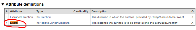
Upon import, is the
depthattribute accessiable in blender via a modifer or similar?@theoryshaw the depth will be implicitly shown in the object itself. Internally it will be stored - maybe it should be exposed hmm :)
Blender's extrusion modifiers (solidify, or curve extrude) only extrude normal to the plane. This is not sufficient to support the custom extruded direction feature of IFC. Also, an object may include both extrusions and BREPs simultaneously - Blender will be able to handle them, but it means I cannot use modifiers.
Amazing development @Moult !
In any case this is a slippery area, there are many IFC cases that don't translate 1:1 to neither Blender or FreeCAD (or Revit for that matter :D ). But circles are a convenient thing to support since they appear a lot everywhere in buildings and you can usually reduce your filesize by a big factor. Maybe just a kind of "export as circle" switch somewhere would be sufficient? Then you could easily deduce the radius I think, from the center point and one of the vertices
@Moult is the profile exposed too in blender? If not, I feel it should. Otherwise I feel it would be cumbersome to modifiy the profile in blender, as you would have to 'explode' and re-extrude.
Retaining the profile, would also play into accommodating 'mapped profiles' in the future--could tap into libraries like these: https://github.com/OpeningDesign/BIM_Profiles
--
Also, I would say a vast majority of extrusions in AEC are normal to the direction of the profile. Is this one thing we could be strict on? Would this help to develop an implementation where the profile and extrusion distance were exposed in blender?
Would extruding a 'Nurb Circle' verses a 'Mesh Circle' be a better approach to emulate a true circle?
Would translating IfcExtrudedAreaSolid into a 'bevel extrusion' via blender, be a better approach?
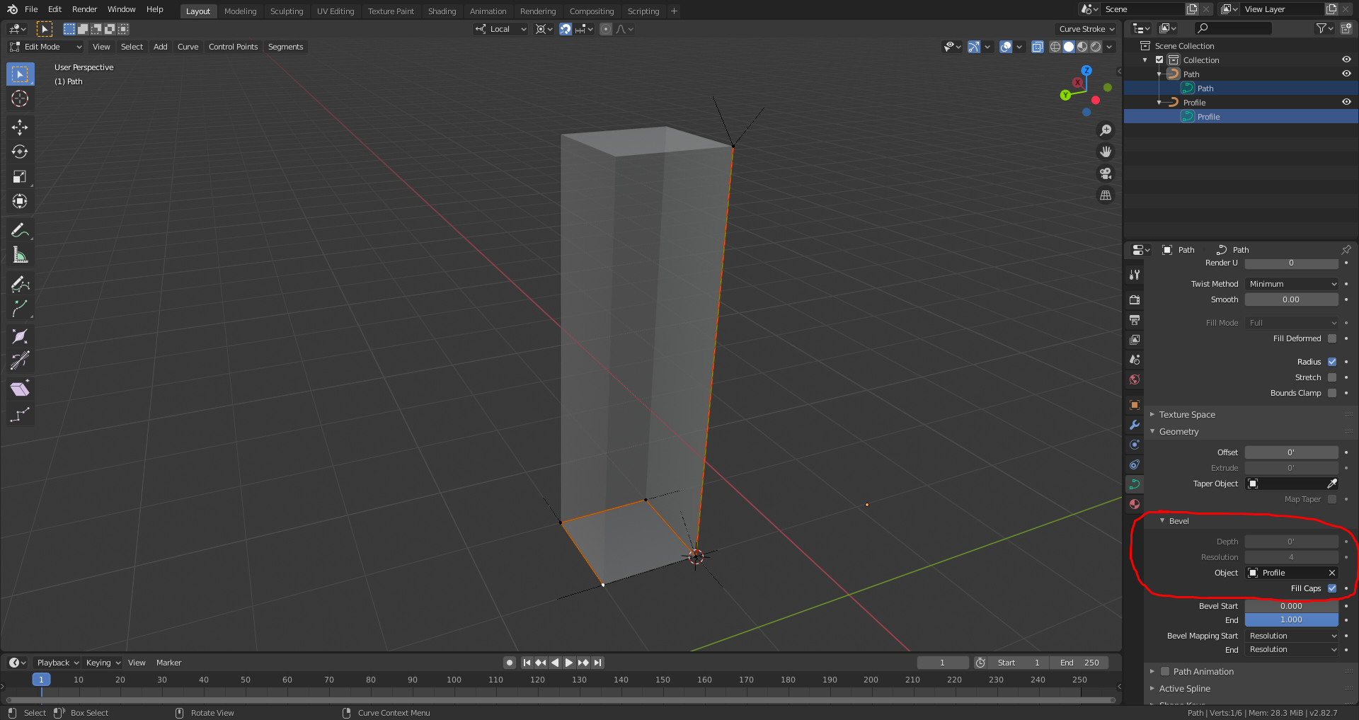
I'm a blender noobie of course, but seems like 'mapped profiles' could be done like this.
@theoryshaw I've considered those options - there are a few downsides to a Blender curves approach (applies both to arbitrary profiles and circles - note that Bezier-based circles are not true circles, they are approximations ... not that the error factor matters though!)
@Moult this is my friend's view:
@ReD_CoDE your friend is correct. My statement should've been about Blender's bezier curves. I have modified my post.
https://github.com/IfcOpenShell/IfcOpenShell/commit/d3f07c4ac48e85e714073b9c213a90a5797793f4
@theoryshaw The BlenderBIM Add-on can now round-trip IfcArbitraryClosedProfileDef and IfcRectangleProfileDef :) Will be in next release! Full log here.
Nice!... look forward to testing.
BlenderBIM passes! :)
https://gitlab.com/osarch/FreeMVD_WorkFlow/-/commit/86534ac85dd9cd5c6ad8fc9d9531538a885c72ca
Although post editing the profile's base polylines, however, in Blender seems cumbersome. Well, for this noobie, anyway.
Right now, just the functionality is implemented. Usability has still to be debated :) I have a hunch that for most cases, you won't need to inspect the vertex groups at all and just edit it leave it as that... but I won't know until I've used this more on actual projects :)
Also pay attention at material indexes, with curves you loose control of "by segment" material id.
Are you talking about an extrude direction not perpendicular to the profile? Such as what's illustrated below?
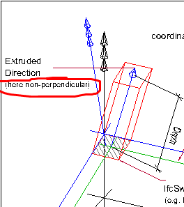
I 'think' I know what you're talking about here, but can you provide an actual test file that illustrates this condition, just for my own education?
Correct, the extrusion directly does not need to be perpendicular. In Blender, this is easy to create - and when it imports into Revit, it actually turns itself into a "sweep" object with two profiles. Will provide a test file soon.
This first file is an example of a non-perpendicular extrusion:
This second file is an example of two extrusions with different distances (though the profiles can change too!) in a single object:
For each, I have produced the extrusion either as a rectangular extrusion, or as an arbitrary closed profile. What I discovered on my Revit 2019 install (please check on yours) is that linking the rectangle extrusions works, but opening the rectangle extrusions do not work. If you open the Revit file generated by the linking process, you get an uneditable object. However, if you open the arbitrary extrusion version, Revit will let you modify both the sloped, and the multiple extrusions. That suggests to me that round-tripping rectangles perhaps isn't a good idea with Revit - what do your tests show?
Thanks, yes that's what I thought you meant by multiple extrusions in a single object.
...
Added your files and some other results in the 'random tests' folder...
...
Yes, rectangular profile does not translate in Revit.
...
A non_perpendicular_extrusion_direction is not translated into Revit upon import--it creates a 'blend' with a top and bottom profile. And upon export, it created a faceted Brep.
...
I plan on creating more official tests for these in the near future.
Bug reported for Revit: https://github.com/Autodesk/revit-ifc/issues/209