

How to intersect IfcMaterialLayerSet's of IfcWall and IfcSlab

I have looked into the possibilities of IfcMaterialLayerSet in Bonsai v0.8.3-alpha250622-98c479f . I wanted to intersect an IfcWall with an IfcSlab. I had hoped that it would work in a similar way to intersecting walls (keyword: intersection priorities), but I couldn't find a workflow in Bonsai that would have allowed me to do this intersection.
Is there a description or a video tutorial for this?
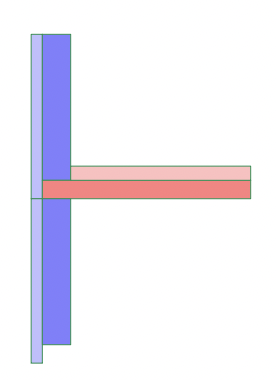
Here is a picture that symbolizes what I want to achieve. It shows a vertical section through the connection of two walls with a ceiling in between. The darker colors symbolize the load-bearing layers.
Perhaps someone can point me in the right direction.
Tagged:
Comments
@kurb70
Maybe this won't answer your question but, if interested, I personally find more practical using IfcSlab.FLOOR and IfcCovering.FLOORING as different elements.
It also helps me separate the structural part of the model from the rest, important for quantity purposes.
Thanks for the suggestion. Yes, I agree that it makes sense to model structural elements separately. I wanted to find out if I could also work with this type of intersection in Bonsai.
My specific concern is that the light blue layer covers the front of the IfcSlab. That's why I tried to intersect the layers of the IfcWall with the IfcSlab.
In that case you might want to try IfcCovering.CLADDING and IfcWall.SOLIDWALL ? ;)
It also depends on the construction method I guess
I agree.
I do the same in my commercial BIM Apps. A Structural Slab that runs through the whole building + another Floor Slab package on top which is added into each room. Besides differences between outer and inner Wall's Slab connections which may or may not work well with a complete single multi-ply, it also needed as you may often have different Floor Packages in different rooms.
For the Walls I usually use complete multi-ply Wall Styles/Compositions. First because they usually offer Settings for propper Slab connections but second, mainly because you usually can't insert Doors or Windows into more than one Wall Object. Otherwise, if insertion objects could cut into multiple Objects, I would also prefer to separate Walls into a structural part and a Finish/Insulation Package part, like I do with my Slabs and Floors.
At pre-BIM times I would have modeled Walls below and above Slabs and an extra insulation skirt with slab height around the Slabs .... since BIM I can usually set Walls with different top and bottom adjustments for each Ply.
@zoomer
sure you can insert doors and windows with their openings through all layers (wall + claddings), via aggregate
or maybe I didn't fully understand your point, thanks
I wanted to mention that @kurb70 's question/problem isn't really a Bonsai problem or workflow and that I think that your proposals are quite BIM modeling best practices . And that I do the same in my commercial BIM Apps.
Not very experienced with this term ....
(In the past I had a problem loading an IFC (Walls) into BlenderBIM. Dion found that I had IFC exported with "Aggregated" Walls option on, which BB at that time did not support and Dion fixed/implemented that, because "Aggregated Walls were an IFC standard)
So an aggregate is basically whatI call a stylized Multi-ply Wall or multi-ply Composition Wall - as an aggregate in IFC, a single object but containing ply information.
So, yes, doors/windows will cut through all plies that way.
But didn't @theoryshaw also experiment with applying a single Void to multiple Objects to cut all of them ...
My Bricscad was the first BIM App I knew that got such a feature lately. A bit cumbersome to use and too late in the project or model stage. But I am very excited about such an option for reasons I mentioned above.
Or when I saw a FreeCAD video, that inserting Windows will cut anything (!) that is in reach of its (adjustable) cut depth (?) which I found pretty useful. (But could be that this only happened because all these Walls may have been modeled as a single object ?)
well, to the best of my knowledge you can have a multi-layer element (wall, slab, covering, etc) using material set, or
you can have distinct elements (wall+covering or similar) aggregated in an IfcElementAssembly, in this case the opening like door or window needs to be assigned to it to affect all aggregated elements
I find this method particularly useful to assemble trusses for instance, or composite walls (plate+stud+gypsum board+..)
OK, I think I mixed that up.
A standard export Wall may be the single geometry with material set only, while the "aggregated" export may come in as an Assembly of multiple Objects ... or so, but I would need to test and look a bit closer.
Thanks for all the feedback. Essentially agree that structural elements should be modeled separately.
However, I wanted to find out if it is possible to intersect an IfcSlab with an IfcWall in such a way that one layer (in this case the load-bearing wall layer) can be “cut” from the load-bearing IfcSlab so that the external insulation layer remains as insulation on the face of the IfcSlab.
Would be a nice feature request.
I could write a whole essay about my experience with my commercial Apps here .....
Both work completely different, that is why I have both, on purpose. One is "history based" and parametric BIM Modeler (Vectorworks) the other a "destructive" BIM Modeler (Bricscad)
In VW you can apply parametric "Height Levels" to your overall Wall Z's and each of its Components/Plies. Similar is possible for Slabs and their Components in X and Y. So you can draw in 2D top plan view and everything automatically fits. If you later need to adapt your parametric Story or Level heights or Wall/Slab Styles, all geometry will adapt automatically also.
So once you set up all your parameters in Story/Level Settings and BIM Object Styles (which you could prepare in your project file template) , you can draw/model from start super fast !
In your case you would set your Wall Style, for overall Wall height from Levels - bottom = "top of Slab" and top = "bottom of Slab - Story above" generally. For your Wall's Structural/Core Ply's bottom = "top of structural Slab" and top = "bottom of structural Slab - Story above" - while your insulation Plies are set to bottom = "bottom of structural Slab" and top like the overall Wall.
Similar for your Slab Style. Structural Ply = to "outsideof Wall Core"
(If you would also have Floors Plies included in your Slab, you would set these to reach until "inner side of (overall) Wall)
This would give you your desired Section detail. (The Insulation package exceeding the Wall at the bottom as a skirting in front of the recessed Slab. All by defining how each Plies are reaching, no boolean or cut actions needed.
Such a System can be insanely fast. As you basically just draw outlines in top 2D and get a perfect detailed 3D BIM model for free. The downside is, if your design/existing is a bit off of standards and you reach the limits of parametrics and given Tools. You are basically lost and lose all comfort as you have to model everything manually with dumb Solids.
The opposite System is Bricscad. You are beginning just raw Direct Modeling Solids for (overall) Slabs and Walls and classify the with IFC tags later (or let that do for you by their ML/AI automatically). For the next LOD you define and apply "Compositions" which are like multi-Ply Wall or Slab Styles.
In your example - your overall Wall would now just sit on top of the Slab, the Slab would reach until outer side of Wall. To apply to your desired connection detail, you would enter a higher 3D View LOD mode, where you can see all "Component's" Plies. Where you can now select each, one ore more of its Ply's Faces and modify them individually by PushPullTool.
So this way you are totally unlimited in BIM modeling for any LOD however complex your design/existing geometry will be - but it is slow and tedious as you have to change each Object's (sides !) manually.
(But again, you edit one detail situation and use Bricscads AI/ML solutions to "propagate", means it will search all similar situations in geometry, which you can accept or reject individually and it will adapt the for you automatically !
Side note.
Each approach has its advantages and culprits but also its needed Tools !
if you were used to a parametric/history based Modeler before and come to a destructive Modeler you may feel completely lost and inefficient, but usually destructive Modelers have all Tools needed to circumference their possible disadvantages (Better Selection options, Soft Selections, ..... to give you similar control and speed.
Same if you come from the opposite side.
TL;DR;
For Bonsai Modeling, as far as I understand it so far,
I would more think of comparing it to my second example - the distractive modeling approach (like in Bricscad).
I think you would need to search a way to enter the aggregated Wall "Assembly" and manipulate the outer insulation Ply's bottom downwards. And likely it is needed to push the Slab's side faces back in (?).
Or start by the structural Components of Walls and Slabs and try to integrate the insulation Plies package later into the Walls "aggregated" assembly (?)
Or better modeling all in plain Blender first and try to "Bimify" it from here in Bonsai afterwards ?
Sorry for the text wall.
But I think that is something essential for Bonsai's future BIM Features and Layouts.