

Assigning wall type to mesh resizes the mesh

Continued from: https://github.com/IfcOpenShell/IfcOpenShell/issues/7451
Hi @theoryshaw .
I certainly hold my hand up as a beginner and I'm still learning. But why does the type I wish to apply change the fact that my mesh converted walls are moved?
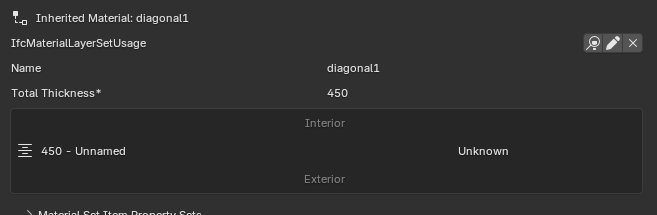
A wall created with the wall tool is fundamentally a 2d polygon extruded to a height. The type applied to it makes it a layered wall, not the fundamental geometry. A wall can have as it's geometry as mesh instead of an extruded polygon. Are you saying that a particular type (layered in this case) can only apply to on top of one geometry method, to extruded polygon or mesh but the same type can't apply to both? I believe it can, as a workaround I have been adding mesh converted walls to my IFCRELDEFINESBYTYPE list. It's not 100% right doing it that way, this is a Bonsai generated wall:
And this is a mesh converted one.
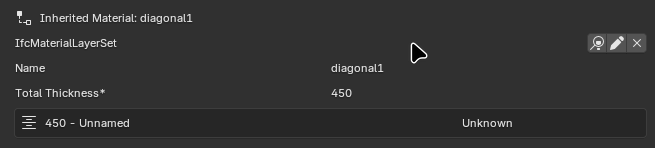
There must be more relationship tags needed to make my mesh geometry wall totally equivalent to a Bonsai created extruded polygon geometry wall.
But fundamentally a wall can have either type of geometry. A layered wall can have either type of geometry. Bonsai should not be touching the geometry of a wall when a type is applied to it. Hence the bug report.
Comments
This is an AI answer, but aligns with what i know as well...
...
I understand your concern, and you're right to question this behavior. Let me clarify what's happening and why this is actually the expected IFC behavior, though I can see why it feels like a bug from a user perspective.
Why the Geometry Changes
When you assign an IfcWallType (especially a layered wall type) to a wall instance, you're not just adding metadata - you're establishing a type-instance relationship where the type can define:
IfcMaterialLayerSetUsage)For layered wall types specifically, the type contains instructions for how to generate the geometry based on:
This is by design in IFC - the type acts as a template that generates appropriate geometry.
The Core Issue
You're experiencing a conflict between two different approaches:
Approach 1: Explicit Geometry (Your Mesh)
Approach 2: Type-Driven Geometry (IFC Standard Behavior)
Why Your Workaround Works (Partially)
When you manually add the wall to
IFCRELDEFINESBYTYPE, you're creating the relationship without triggering Bonsai's geometry regeneration logic. However, this creates an inconsistent IFC file where:The Correct Solutions
Option 1: Create a Non-Layered Wall Type
As @theoryshaw demonstrated, create a wall type that uses IfcMaterialConstituentSet instead of IfcMaterialLayerSet. This type says "the wall is made of these materials" without specifying how to generate the geometry.
Option 2: Don't Assign a Type
If your wall has completely custom geometry, you might not need a type at all. You can:
IfcWallwith your custom meshOption 3: Use the Type as Intended
Create the wall with Bonsai's wall tool, then let the type generate the appropriate layered geometry. Edit the path/axis if needed, but let the type handle the cross-section.
Is This a Bug?
No, this is correct IFC behavior, but I understand the confusion. Bonsai is doing what it should: when you assign a type that defines how to generate geometry (like a layered wall type), it regenerates the geometry to match.
The real issue is one of user expectation and workflow clarity:
Recommendation
For your workflow (custom mesh walls), I'd suggest:
Your mesh walls can still be valid IFC walls - they just shouldn't use types that expect to control geometry generation.
...or perhaps i'm missing what you're asking.
it depends on where your origin (and its rotation) is on this instance, that you're converting to a type-drive one, too. That's important too, if you want your instance to stay put in the same place, so to speak.
@Julian
my 2 cents here, over simplistic approach:
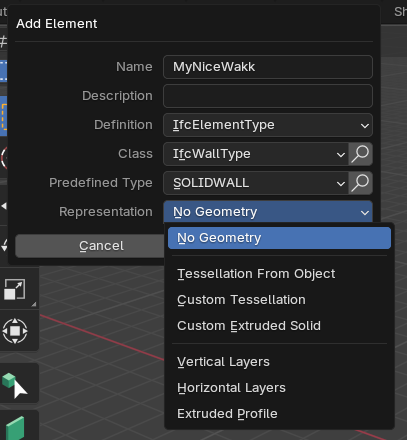
you can have a wall type with different methods, forgive me if the terms are not technically accurate or don't sound something new to you.
tessellation
extruded area solid
vertical/horizontal layers
extruded profile
In summary, if you start with a mesh geometry your only chance is to use method 1, if you need a layered wall use method 4, and so on.
Assigning a type 4 to a mesh doesn't make much sense 'ifc-speaking' (but I might be horribly wrong here)
Not knowing your starting geometry and what you are trying to achieve is hard for me to be more specific.
Hope it helps somehow.
Happy modelling
I can see now that I have an awful lot of learning still to do. Vast amounts!
I see what it is saying, I think. The type of wall and what I am trying to do are mutually exclusive. I'm using mesh conversion because I could not find a way to create two wall elements; basement level of a wall on a slope and a gable. Both of these have variable height which is incompatible with a system that is geometrically defined by orientation, length and height.
I've been running my model through the BuildingSmart validator, it may be that one of the normative warnings is telling me I've applied a layered type to an incompatible geometry. Now I understand a little more I'll look at them again. There's no errors in my model, I validated it before and after adding my first mesh converted wall to my layered type list. I would have discarded that approach had there been a new error. Not that it matters, you've already shown me where to look to see that my workaround was not fully working as shown in my screenshots above.
The layering approach looks, based on the little I have seen so far something I need to understand. The walls will have external wall insulation applied. The wall will get thicker, having it automagically redrawn simply by adding some new layers to the type, 100mm of insulation, 6mm of render and 30mm of stone slips (oversimplified) seems attractive. I'll explore the rabbit holes called IfcMaterialConstituentSet and IfcMaterialLayerSet and see where they lead.
Thankyou @theoryshaw for taking the time to explain a 2nd time and I apologise for not understanding from your video.
{Aside: I did not know AI was capable of producing that fidelity of answer. Two learnings in one :-)}
The pendant in Archicad are favorites. Not sure, but I think if you are open an .ifc in ArchiCad the types are converted to fav's. Same concept are Revit families.
If you are think e.g. about windows, you have created a windowtype with 2 glasses and width/hight and placed the instances in the model. Now you have to change all this windows with some with 3 glasses. So you just create a new type and change all (windows) together. If the cardinalpoint (origin) is the same the geometry will be updated, everything stays in place and also psets... (like heattransmit, same for materials,...) are right. (If defined and stored)
@Julian
if you read my comment I forgot to mention that geometries can be further edited with voids and cutting planes to achieve what needed. Again, if possible, a snapshot of your expected result would be very helpful.
Thank you @steverugi,
I'll add those rabbit holes to my exploration list!
Ah ha! Are cutting planes the correct solution to the problem I hit (variable height walls)? I'll try that & see.
I do like a day in which I learn something and today I'm learning a lot!
@Julian
In Bonsai/IFC lingo they are called "IfcHalfSpaceSolid"
Shiift-O to add a void
I've been playing and yes @steverugi, this was the correct solution to my uneven height wall problem. Forgive me if I'm teaching my grandma to suck eggs (wierd ancient English saying) but if there's anyone following along struggling with the same here's what I've additionally learned (the half space solid tool isn't obvious to find):
1. If you only want a simple slice off a wall create it, then select it and hit tab once and then you will see in the top menu
+ Add It...appear. Don't worry about trying to resize the IfcHalfSpaceSolid, that's not necessary as it cuts to infinity along its plane. It looks like the IfcHalfSpaceSolid in @steverugi's pic 1 won't fully cut the corner off the wall as in pic 2 but it will.2. If you try to move the IfcHalfSpaceSolid precisely with g, x, 1000 (for example) it may not move. Wiggle the mouse between the g and the x. Once it is moving it will respond to axis & distance typed.
3. The perpendicular arrow indicates the section removed.
But you can't make a concave cut with IfcHalfSpaceSolid, for example to create a gable wall with chimney:
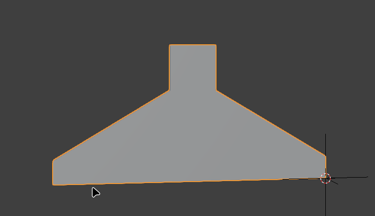
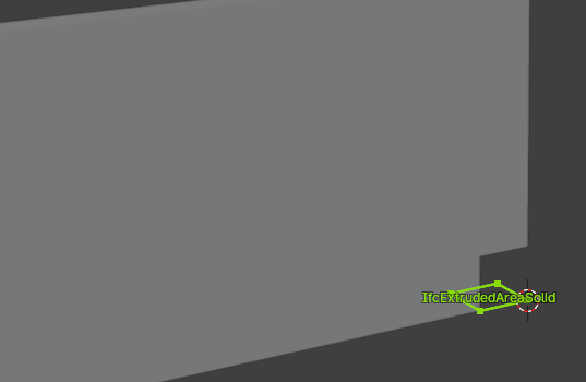
For that use the add void tool (easily found):
1: Select the wall and add a void. It will be placed at the cursor location (red/white circle) so it helps to move it to the wall with shift+rightclick first.
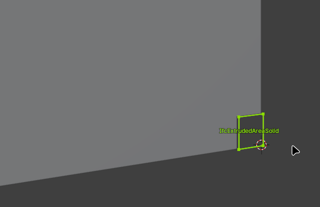
2: A void is another extruded plane and the plane is by default in the same axis as the base of the wall. You can't adjust the height of it same as you can't independently adjust the height of points along a wall. Tab twice into it and you'll see this:
3: So rotate it 90 degrees. Again, if it doesn't respond to numeric inputs wiggle the mouse and then type the desired rotation.
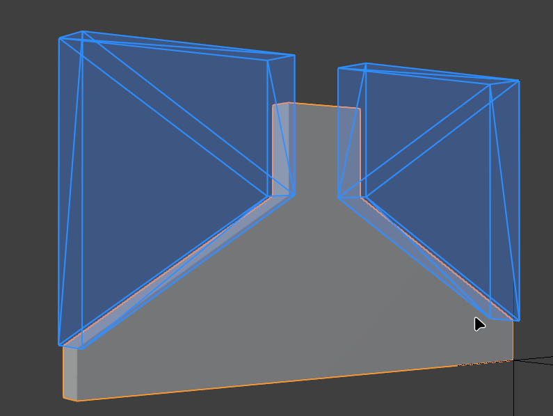
4: Now you can move the nodes & edges as required to create a concave cutout. Duplicate & rotate and you have a gable wall with chimney:
That's enough for today, thanks once again to @steverugi and @theoryshaw . I'm off down those reading rabbit holes before recreating the shaped walls within my project correctly tomorrow.