

How can I model a ramp between walls with varying height in Blender / Bonsai?

I want to create a ramp in Blender between several walls.
While creating the ramp, I need to change its height from one end to the other, and the walls along the ramp are also curved.
So the ramp needs both a varying elevation and a complex/curved path.
Is there any recommended workflow or tool for modeling such a ramp in Blender/Bonsai?
Comments
You'd have to model this with Blender tools, and then 'bake it' into .IFC.
There's currently not Bonsai tools, that i know of, that allows for this to be done parametrically.
Thank you for your response. I tried doing this with Blender, but the result is not a smooth ramp surface. The ramp created using this method ends up with a lot of bumps and irregularities.
I need the ramp to have a completely flat and clean surface, because in the next step I want to create an IfcSpace on top of it, which requires a perfectly planar geometry.
Can you share the file, and what tools in blender did you use to create this ramp?
Is the ramp, a spiral?
@Erfan_Hoss
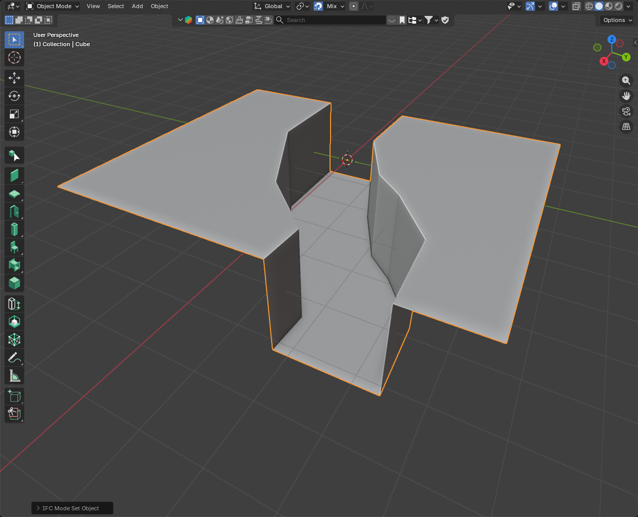
if you select the two curved sides on top and use (edit mode) Edge > Bridge edge loops you get something like:
first Method.> @theoryshaw said:
Yes, the ramp is spiral.
In Blender, I created a Cube and modified its geometry in Edit Mode so that it fits between the ramp walls. I did this by extruding faces or moving the cube’s edges and vertices. After that, I assigned an IfcRamp to the created Cube.
This can also be done as follows:
Go to Add → IFC Element → set Definition to IfcElement → set Class to IfcRamp → set Representation to Custom Tesselation → OK.
This creates an IfcRamp whose geometry can be edited. Then, by entering Edit Mode, you can repeat the same modeling steps described in the
Thank you.
I didn’t quite understand it.
I’m having trouble creating the ramp shown in the first image you sent
Do you mean that the curved ramp should be created using Bridge Edge Loops?
I would appreciate it if you could explain this in more detail.
@Erfan_Hoss you can also try it this way... (there are more ways, from calc points to geometrybased, boolean,...)
Note you can hide also faces in Editmode "H"
@Erfan_Hoss
Quick 'n dirty procedure I know, maybe something more professional is available?
Edge > Bridge edge loopsto create your ramp that exceeds on the XY the actual one (from top view it is larger than the one you need)now position (align) the 'gross' ramp and your solid built on the wall lines
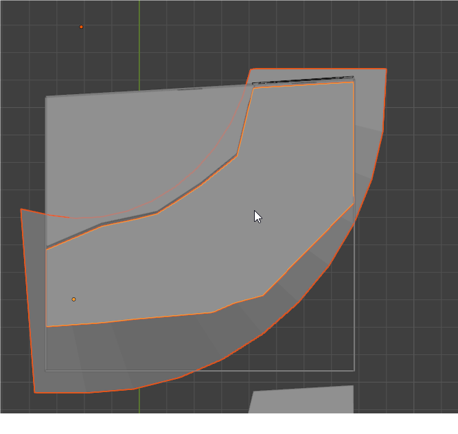
use boolean 'Intersect' to create your ramp
The zig-zag of your walls complicate the process a bit but the 'smoothness' of your ramp is determined by the number of vertices you use in your curves.
Hope it helps
@Mas
@steverugi
Thank you both for your help.
I will try both methods and let you know the results.
@Erfan_Hoss
@Mas ' method is smart but IMHO it rotates a plane (made out of co-planar vertices) along 1 axis, in your case you have two curves 'spiralling' on the z axis to be joined to form a sort-of plane.
I'd like to learn more on this topic if there is a good solution to it.
Cheers
@steverugi I know you need to have some slope somewhere, normaly imo there is the slope to the inner radius, because I´m a little lazy I did it with a plane and a little bit of "sculpting".
If knowing the further streetcurves, it would be easier to find a more mathematical/geometrical solution.
My fast solution is attatched. (but there is a lot more geometry in now, but it´s nearly smooth, one time subdivided)
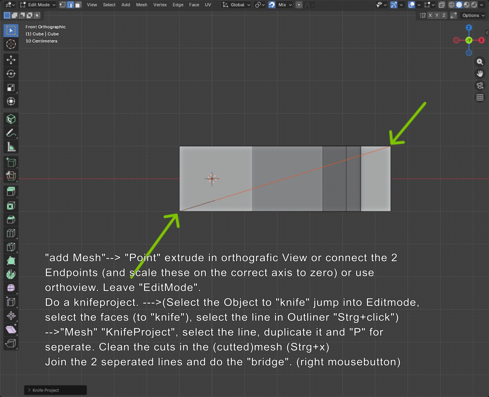
KnifeProject and "Knife" is also a possible solution. Thought also about generating 2 or 3 (converted) curves for cutting.
Yet another way to skin this cat: A mesh with just a single horizontal edge, and using a "screw" modifier:
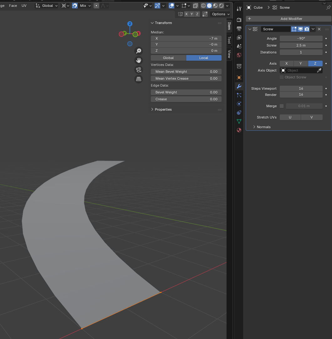
It will still require additional scaling and tweaking, but it is a real quick and easy method. Optionally use a solidify modifier to give it thickness. Once happy, you must apply the modifiers - they will not work with Bonsai.
Just for info knifeproject is viewbased, to adjust the angle with numpad and cut (through) is a cool feature.
💪🏻🖖
I tried all the methods you suggested. Thank you very much.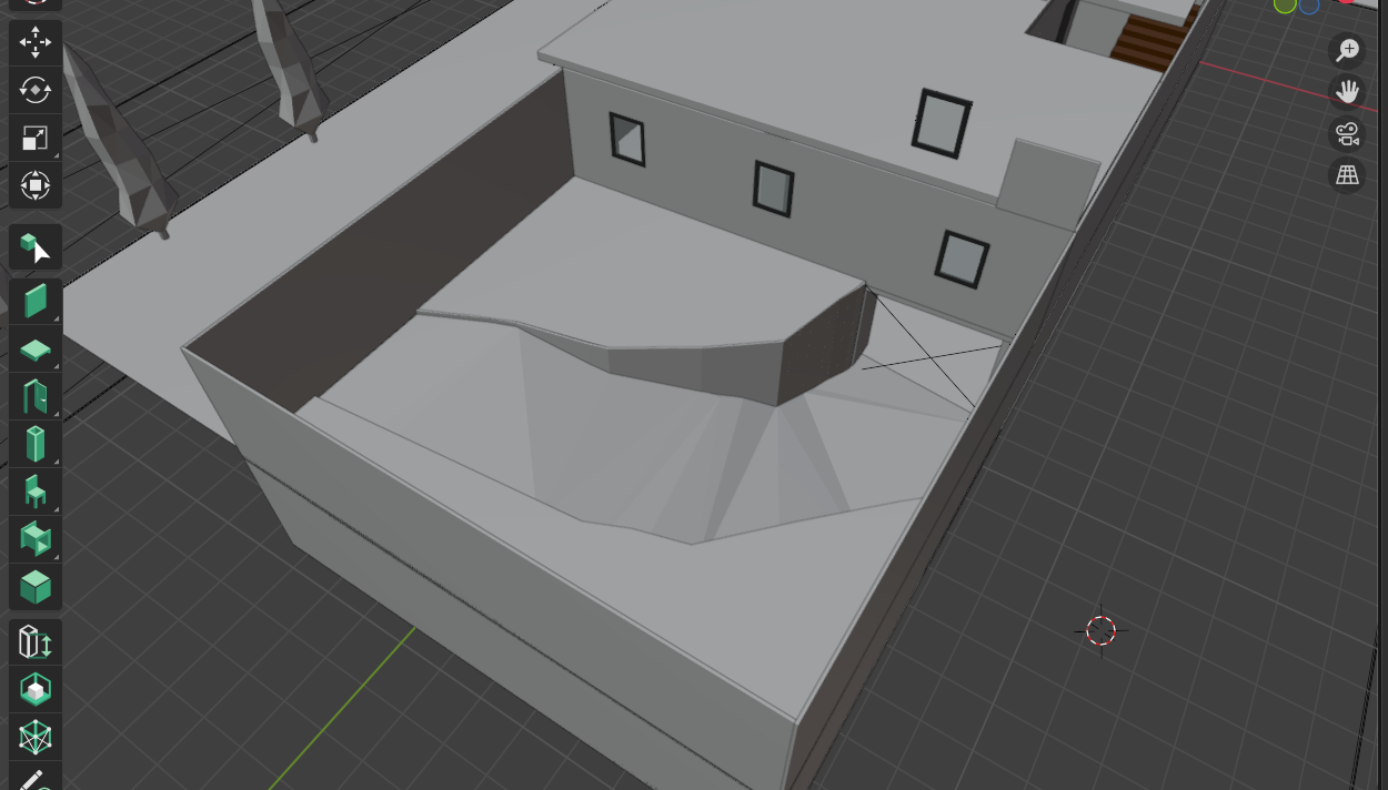
The method by @steverugi was good. I followed it through to the end, but I ran into an issue when applying the Boolean Intersect operation.
The approach suggested by @sjb007 was also good; however, since I have zigzag-shaped walls around the ramp, it seems that this method cannot be applied in my case. That said, I would be happy to hear any ideas or suggestions.
In the end, I managed to create the ramp using the method suggested by @Mas . Although the ramp still has some irregularities, it is much better than the one I originally created.
Thank you all for your help.
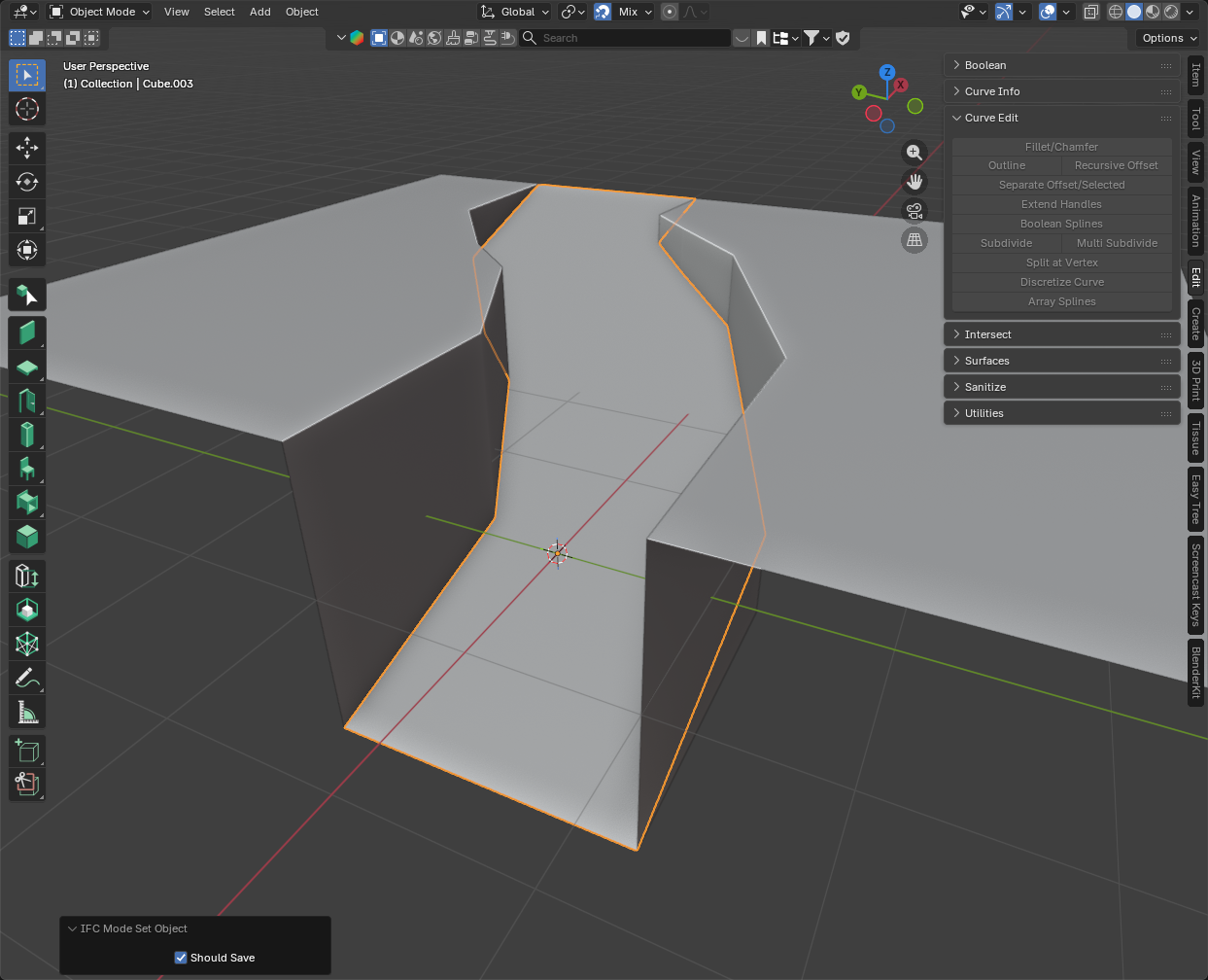
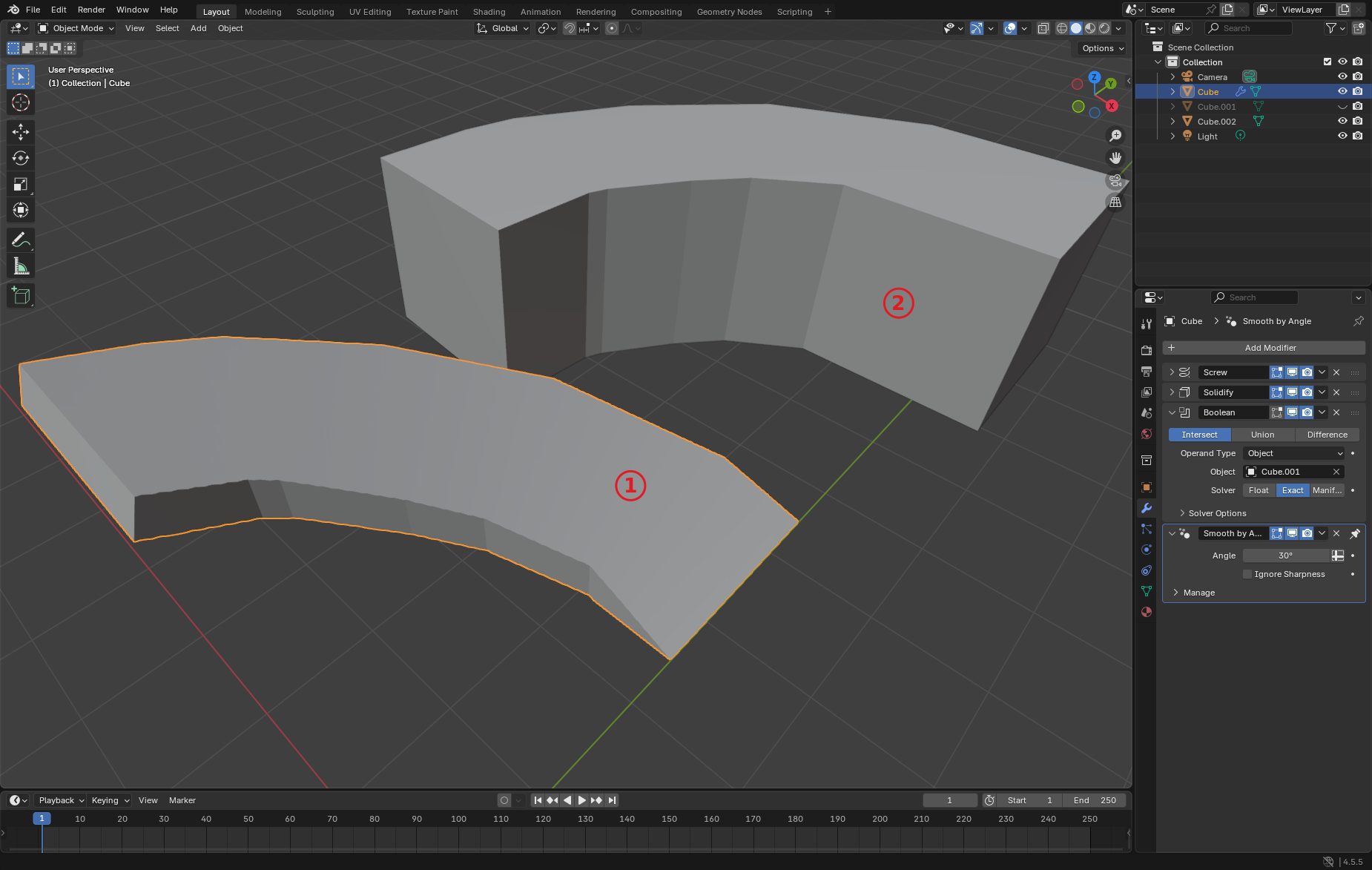
@Erfan_Hoss Just a followup on the zig-zag walls. If you don't want the goemetry extending beyond the jagged sides, you can create a full height block representing the channel (2), then use as a boolean cutter to trim a soldified version of the curve object. This will give (1):
@sjb007 It seems like a good approach. However, which two geometries did you use for the Boolean operation?
One of them is the block shown in part 2 of your image— what is the other one?
In that image:
Cubeis what turned into the ramp object (1). It started as the default cube that gets edited to be a single edge that then gets theScrewmodifier applied. It then gets a solidify mod, followed by the Boolean with Cube.001, and last but not least Smooth by Angle.Cube.001is the hidden object used to do the boolean onCube. It has to be in the correct location, and is hidden so you don't see it overlayed.Cube.002is a duplicate ofCube.001. It is only there so it can be offset and made visible to demonstrate the shape ofCube.001Of course none of this modifier magic is compatible with Bonsai/IFC. So once happy with the object you
Applyall the modifiers, turning it into a base mesh, then in Bonsai assign it an IfcClass. Same goes if you turn it into IfcSpace's.