

Standard Workflow for Electrical Drawings in BIM for Contractor / Client Presentation

Hi,
I’m trying to understand the standard workflow for preparing electrical drawings in BIM and presenting them to contractors or clients.
If we model electrical elements such as switches, lights, and equipment in an IFC model, how are these typically converted into electrical drawings for construction?
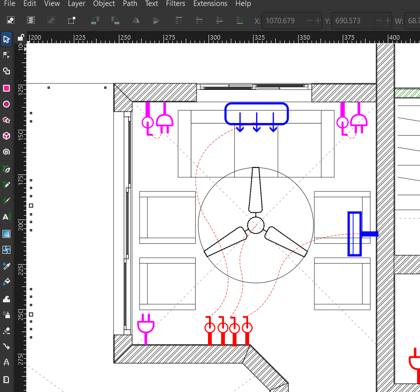
Currently, to give drawings to the contractor, I am creating a separate 2D graphic using electrical symbols in Inkscape. I’m wondering if this is the normal approach.
What is the widely used or recommended workflow for producing electrical layouts from a BIM model?
How are these usually delivered to contractors — 2D drawings extracted from the model, annotated plans, or something else?
Experts, please enlighten


Comments
I took the approach of putting the symbols in the
drawings\assets\symbols.svgfilefiles: https://hub.openingdesign.com/OpeningDesign/Restaurant_Pewaukee/src/branch/main/Open/Models/BlenderBIM
I also explored adding 'really really tiny' text next to each symbol, that gave more details, if you like zooming in really far on the pdf. :)
Do I understand it right that you add them just as a 2D annotation to a view? Why not as a plan representation of the element itself?
The ifcannotations are tagged to ifcelements. That is, the annotation tag is pulling out data (psets or attributes) from the associated IfcElement.
Cool! So you present plans with the symbols an their height is mentioned in the schedule so that we dont need a section/elevation .
Is the schedule atomatically updated when we change the description, or should we export csv and then create svg to import as schedule each time with changes in description?
Impressive presentation sheets btw!
Thank you.
You could do it either way, just depends on your preference.
For the majority of these tags, in this project, I tagged them to the actual equipment or plumbing fixture object--verses an actual outlet or pipe object, for example--although you certainly could. You could create an annotation tag that 'pulled out' the Z dimension of an object in space.
...
There's no automated approach that i know for schedules... you still need to export out your csv or .ods and then 'rebuild' this schedule as an svg, if you want your sheet to have an updated schedule.
One more thing: you mentioned that these project files are open source. If they are open, wouldn’t there be a security issue? I mean, the building blueprints would become public and that could create security risks, right? How do you see this issue when making the plans public? @theoryshaw
My projects are small and inconsequential... a house or small commercial job.
It might be a different story, perhaps, if it was data center or a skyscraper, but even then i think you could come up with counter arguments.
In a similar vein, people worried about the security of open source software, in general, but ironically it has played as being more secure in a majority of cases.
https://claude.ai/share/6a084ced-ca34-4967-9c75-1f1210470ad2
In general, i think the possible 'rewards' to our society and industry greatly outweigh the possible 'risks'--but isn't innovation always on this edge? :)
A lot of times, it seems, it's not a technical problem, it's a conventional wisdom problem.
https://claude.ai/share/000c6388-9218-4376-8bb7-89ebf8ce9c59
it's a conventional wisdom problem.
I have no doubt about the security of open-source software, and I support making designs open source as well. However, as consultants, we design for clients. I’m not sure about the legal terms regarding whether the client owns the design or whether we can publish it without their consent.
I would like to make my designs public. Do I need the client’s permission to do that?Their argument might be that if the plans are public, robbers could study them and plan their actions more easily if the shared model as sensitive data like camera positions, server room locations etc. How can we defend that argument or solve that issue?
Yes, i get the client's permission.
I actually tier my fees in favor of the open source approach.
example proposal: https://hub.openingdesign.com/OpeningDesign/AECO_Contracts_and_Proposals/src/commit/8c53c13f6159fdddf829e9f54fafe65d32787617/Out-in-the-Open/Master Proposal/_Master Proposal.md
Specifically, it's up to the client. They can opt for the more 'conventional approach', but more often than not, they choose the open source approach because a large majority of our built environment is not the target of wrong doers.
There are lot of historical examples where "where security fears throttled innovation",
https://chatgpt.com/share/69adc0f7-d3cc-8013-b9e3-60a461f00697
Who knew we'd go from 'how do you show outlets on your plans' to the existential pros/cons of open source plans.
Love it. :)
Your answer is more than enough for me to digest :). Feeling i am a real beginner in Electrical diagrams. Hope there will be more robust tools in Bonsai/ ifc to deal this. Seeing all this I Need to streamline my Electrical workflows, thanks for the efforts @Hans!
would openmodelica be an option for simulations\calculations?
a good structured ifc can be represented as a graph? ids bsdd and other bim tools are there to make a kind of ontology? topologic(py) used to be able calculate distances between f.i. rooms? oh.. following these threads since years, and still no idea of what bim is and can do.
qelectrotech does not calculate.. it will need some ifc plug-in to transform a bim model into electrical schematas..
getting closer to a electrical workflow..still a long way to go..
Thanks Hans,
found this (but not understand :-) ) https://hal.science/hal-02365012/document about BPMN.