That MEP bend got me, the fillet procedure was breathtaking! Awesome stuff
Could something like that work for walls as well? That'd be extremely useful, and solve the common case of adding rounded corners tangent to both adjacent straight walls.
Absolutely gorgeous! Now I know where your nickname comes from :D
Having joints adjust dynamically as we move segments is terrific. If that works with any extruded profile geometry, it will also be great for metal structures and frameworks. Pretty cool.
From you videos your gizmos already seem to be able to break walls into separate parts, and create new ones, maybe an extruded profile along an arch can be created from the directions of the adjacent walls.
Thank you @Gorgious, impressive work!
My 2 cents:
For MEP, in cases where the fittings are not geometries created in real time but are instances of IfcTypes.
It would be amazing if there was a possibility, at the time of editing the connection, to see a popup (with the existing IfcTypes) to select the appropriate type.
With this, the MEP tools would become very user-friendly; the only thing missing would be the development of a tool for fittings with more than 2 ports, 'T', 'cross', etc... ;)
Here's a few I didn't share yet.
Wall network path similar to MEP path, draws a line connecting each connected wall elements.
Wall fillet
Thansk for the feedback. i feel like it's ready to land as is, I'll stop adding features for now. Current branch has a rather messy commit history (parallel development of many features, performance optimisations and bugfixes using AI agents). I'll take a few days to tidy it up to merge it correctly to main. For anyone willing to test out the features (NOT FINAL, DO NOT USE IN PROD) : https://github.com/Gorgious56/IfcOpenShell/tree/gizmos-8088 @theoryshaw Sure, could you share an example file where I could test out the feature for such elements ?
A comprehensive system to design custom windows, and doors would be nice, for sure !
Edit : Decided to do a more in depth search on the topic. It seems it's a bit more complicated than it appears.
Why can I only pick from 9 window types?
Because those nine names come from the IFC standard itself, not from Bonsai. The IFC schema (the file format BIM tools share) defines exactly those nine partitionings — single panel, two-panel horizontal/vertical, and six three-panel layouts. Bonsai exposes them as-is so the files you save stay readable by Revit, ArchiCAD, viewers, validators, etc.
So can we just add a "CUSTOM" option?
The schema already has an escape hatch called USERDEFINED, so technically yes — but "custom" can mean three very different things, and they don't all cost the same to build.
What are the three things people usually mean by "custom"?
"I want more panels and I want to place the dividers myself." — e.g. 5 vertical panels with non-uniform spacing.
"I want a window that isn't rectangular." — e.g. an oval porthole, a Gothic arch, a trapezoid following a roof slope.
"I want a big grid like a shop front." — e.g. a 4×3 storefront with dozens of panels.
How feasible is each?
Path 1 — custom rectangular subdivision: realistic. The smallest extension of what already exists. Add a "USERDEFINED" choice, let users add as many mullions and transoms as they like with their own positions, and the existing geometry engine can be taught to read that. Saved files stay valid IFC. Best effort-to-value ratio.
Path 2 — non-rectangular shapes: a separate feature, not an extension. An oval or arched window isn't a variation of "panels and dividers" — it's a different kind of geometry under the hood. It needs its own modifier, its own UI, and its own way of describing shape (curves rather than fractions of width/height). Doable, but a parallel project.
Path 3 — curtain-wall-style grids: probably the wrong tool. The IFC standard already has a dedicated entity called IfcCurtainWall for grids of glazing, and Bonsai supports it. Forcing a 4×3 storefront through IfcWindow would mis-label the element and can mess up quantity takeoff, fire ratings, energy reports, etc. The right answer here is "use the curtain wall tool".
What's the recommendation?
Treat the three paths as separate decisions, not one feature. Bundling them under a single "CUSTOM" choice would be misleading: a user picking "CUSTOM" would expect oval + 7 panels + arched-top to compose, but each piece is genuinely different work.
If we only do one, Path 1 is the most useful for the least effort and fits cleanly into the existing modifier. Path 2 is worth scoping separately if there's real demand for shaped windows. Path 3 is best answered by improving the curtain-wall workflow.
Bottom line
More panels and freely-placed dividers: yes, can be added.
Oval/arched/shaped windows: possible, but it's a new feature, not a setting.
Big glazing grids: already a different IFC tool — use that instead.
it can, but a parametric window, as @Gorgious clearly indicated, must be of a custom predefined type if not in the standard set
IMAO It's a logic that might need some improvement ? Instead of offering a restricted set of combinations IfcWindowTypePartitioningEnum could maybe abstract the arrangement and allow a number indicating how many vertical/horizontal panes or similar in a Pset, just saying.
My workaround with non standard windows (or doors) is to use parametric to go as close as possible and edit it to suit my needs, after all what provided with parametric is a very low detailed type anyway.
"I want a big grid like a shop front." — e.g. a 4×3 storefront with dozens of panels.
I also would think ... this type is clearly a "Curtain Wall"
It is just important that you can selectively replace Panels by Door or Windows and may need some freedom and flexibility for customizing the "Grid".
Also I see wide multi sash Windows as Curtain Wall in a Wall.
As they are so wide, they won't be build by a single long frames/jambs anyway
Another thing,
you sometimes have Windows touching other Windows. E.g. a normal Window with a parapet Wall beside a terrace Door.
In Vectorworks that was problematic. So lately they added something like Window Groups. Which is basically a Curtain Wall-like Container that can have any complex shape and inside can host multiple Windows/Doors/Panels/Coverings. Holding the inserts together by an optional outer overall Frame and/or have inner Posts like a CW.
I am not sure how that could help or will work together with IFC format .....
Path 3 — curtain-wall-style grids: probably the wrong tool. The IFC standard already has a dedicated entity called IfcCurtainWall for grids of glazing, and Bonsai supports it. Forcing a 4×3 storefront through IfcWindow would mis-label the element and can mess up quantity takeoff, fire ratings, energy reports, etc. The right answer here is "use the curtain wall tool".
For a moment I thought I would have missed the Curtain Wall tool in Bonsai ...
But as it seems, what comes closest to a CW Tool in Bonsai, so far is the Railing Tool ?
Curtain wall can be achieved I guess through assembly elements and array modifiers but there is no parametric tool as of yet. Will put it on the myriad of feature enhancments ideas that came up while developing this :) IMO railing tool should not be used for that, array is much more granular and schematically coherent.
Did I get that correct ....
when the Gizmos are activated, such as for Doors and Windows,
editing by the standard Parametric Panel is no more accessible ?
Like it finds no Door under the Door parametric entry, which still does appear when I select a Door.
And when I "add Door" with the plus button in the Panel, it switches all Doors in the drawing
and they lose their IfcSurfaceStyles !?
(From that moment on, when creating a new Door, which will have Surface Styles applied again,
but these will be ignored, although they kept their former edited "Render Style.
I may using it wrong ....
(Todays Blender 5.2 and yesterdays Bonai)
@zoomerThank you for the report, sounds like a bug, I will investigate. Some screenshots would be appreciated with your setup. Parametric panel editing state and gizmo editing state are fully coupled so they should be completely in sync. I have not yet touched the materials or styles in the gizmo system so these should be unaffected.
Some screenshots would be appreciated with your setup.
IFC Demo Project, drew some Walls, Slabs and inserted some of the default type Windows and Doors.
When I select a Door or Window here, I will not get the Edit Gizmo.
Also the Parametric shows a Door entry, but finds no Door.
As soon as I hit the Plus Icons to add a Door I get the Gizmo.
But it seems that all inserted Doors and Windows will lose/ignore their Surface Style from now on.
And in Blender there is no more Material applied for the Doors.
Here the Window example.
Parametric finds no Window.
Again, when added a Window in Parametric, Data and Gizmo appear. While the Surface Style gets lost.
(Frame from gray back to white, Glass no more transparency)
Although the IFC Surface Style Settings are still kept in Bonsai.
But somehow lost their connection.
@zoomer no problem, thank you for the feedback. Yup the builtin window and door type from the demo library are not parametrically defined. Adding a parametric definition overwrites styles AFAIK, you have to use the fields in the bottom of the parametric panel :
Testing the waters for a new "Extend orthogonally" gizmo to speed up creation of walls. Any feedback ?
the builtin window and door type from the demo library are not parametrically defined. Adding a parametric definition overwrites styles AFAIK, you have to use the fields in the bottom of the parametric panel :
I did not expect this.
This was very helpful. Thank you very much.
I have overseen this completely ....
Proposal: make the LAYER2 parametric tools IFC-class agnostic
@Gorgious — picking up the thread from earlier, where I asked whether the wall gizmos could work on all LAYER2 objects and shared the model with wall cladding modeled as a LAYER2 IfcCovering. I dug into how the wall tooling is wired, and I think this is a smaller change than it looks, so I wanted to write up a concrete proposal.
The key insight: the geometry engine is already class-agnostic.
The operations that do the real work — extend-to-underside, wall/wall join & miter, unjoin, fillet-corner rebuild — don't actually require an IfcWall. They operate on three things every LAYER2 element has:
an Axis reference line (get_reference_line),
an IfcMaterialLayerSetUsage with LayerSetDirection = AXIS2 (the vertical, wall-like case), and
an extrusion body that gets clipped/regenerated from the above.
connect_wall, regenerate_wall_representation, and the boolean underside clip all read placement + axis + layer set and write standard IfcRelConnectsPathElements / boolean results. None of it inspects the entity type. Per the IFC4 spec, IfcRelConnectsPathElements and AXIS2 layer usage aren't wall-exclusive either.
Where the coupling actually lives.
The IfcWall restriction is only in a handful of gates, not in the logic:
Two predicates — is_wall (gates the edit gizmo, panel, topology poll) and is_path_connectable_wall (gates join/unjoin, read_geometry, opening hosting) — both start with element.is_a("IfcWall").
A few scattered is_a("IfcWall") checks (e.g. resolving which of a selected pair is the LAYER2 side in the underside gizmo).
Fillet-corner state (IsFilletCorner / FilletRadius) is stored on the wall-specific BBIM_Wall pset.
The proposed change.
Gate on usage, not class: replace the is_a("IfcWall") checks with "has AXIS2 layer usage (+ an axis)." A LAYER2 element that is drawn, edited and joined like a wall then is treated like one — regardless of whether it's IfcWall, IfcCovering, etc.
Move IsFilletCorner / FilletRadius off BBIM_Wall onto a class-agnostic pset (I used EPset_Parametric), with a read-fallback to BBIM_Wall so existing files keep working — no migration needed.
Who benefits. Anything legitimately modeled as a vertical AXIS2 layered element with an axis:
IfcCovering — cladding / siding (the original ask).
IfcPlate/IfcMember — vertical panels: partitions, precast/SIP panels, spandrels (its StandardCase default is AXIS3, but vertical use is common).
IfcBeam/IfcFooting — in some situations these class could be modeled as Layer2 objects... varying grade beam sizes, etc.
IfcCurtainWall — when modeled as a single layered leaf (not as a member+plate assembly).
IfcBuildingElementProxy — the generic catch-all.
Explicitly not in scope: IfcSlab / IfcRoof (they're AXIS3 — the targets walls extend to), and IfcBeam / IfcColumn / IfcMember (those use IfcMaterialProfileSetUsage — a profile swept along an axis, which is the separate "profile" parametric family, not this one).
...
Sounds good ! I think it should be separated in a different thread though as this goes quite beyond gizmo changes and is a real paradigm shift that goes to the roots of the codebase. Cheers


Comments
@steverugi haha yeah thank you, it's better. how do you ember a mp4 video ? I tried with a gif but it was like 50Mb and didn't let me.
@Gorgious
here it is, but you need to upload it using "attach image" and select "All Files (.) ",to visualize your .mp4 one from the bottom
and paste it between "source src=" and "type"
cheers
Thank you !
Playing with array openings on walls.
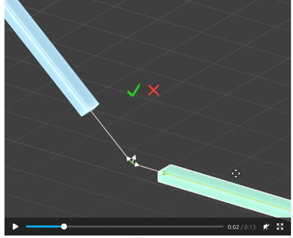
MEP bends.
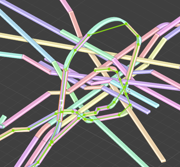
MEP paths
That MEP bend got me, the fillet procedure was breathtaking! Awesome stuff
Could something like that work for walls as well? That'd be extremely useful, and solve the common case of adding rounded corners tangent to both adjacent straight walls.
@duarteframos hehe nice ! I'e got an even better one then :)
Also forgot this one for railings.
Also another one for stacked arrays.
and a snippet of my MEP testings.
Good point about walls, I actually don't know how rounded walls behave in IFC. They're always a pain to design. I'll dig around. Cheers
Absolutely gorgeous! Now I know where your nickname comes from :D
Having joints adjust dynamically as we move segments is terrific. If that works with any extruded profile geometry, it will also be great for metal structures and frameworks. Pretty cool.
From you videos your gizmos already seem to be able to break walls into separate parts, and create new ones, maybe an extruded profile along an arch can be created from the directions of the adjacent walls.
Thank you @Gorgious, impressive work!
My 2 cents:
For MEP, in cases where the fittings are not geometries created in real time but are instances of IfcTypes.
It would be amazing if there was a possibility, at the time of editing the connection, to see a popup (with the existing IfcTypes) to select the appropriate type.
With this, the MEP tools would become very user-friendly; the only thing missing would be the development of a tool for fittings with more than 2 ports, 'T', 'cross', etc... ;)
@Gorgious nice work, per usual!
possible to move the controller off the joint a little, so you can see the joint for visual feedback?
@Gorgious, Possible to have the gizmos that work with walls, work with all LAYER2 objects as well?
Here's a few I didn't share yet.
Wall network path similar to MEP path, draws a line connecting each connected wall elements.
Wall fillet
Thansk for the feedback. i feel like it's ready to land as is, I'll stop adding features for now. Current branch has a rather messy commit history (parallel development of many features, performance optimisations and bugfixes using AI agents). I'll take a few days to tidy it up to merge it correctly to main. For anyone willing to test out the features (NOT FINAL, DO NOT USE IN PROD) : https://github.com/Gorgious56/IfcOpenShell/tree/gizmos-8088
@theoryshaw Sure, could you share an example file where I could test out the feature for such elements ?
It's the most beautiful thing I've seen in a while! Great work, looking forward to playing with it.
@Gorgious you could use this model. It has the wall cladding as an LAYER2 IfcCovering
I hope Bonsai BIM can create more than 3 windows
A comprehensive system to design custom windows, and doors would be nice, for sure !
Edit : Decided to do a more in depth search on the topic. It seems it's a bit more complicated than it appears.
Why can I only pick from 9 window types?
Because those nine names come from the IFC standard itself, not from Bonsai. The IFC schema (the file format BIM tools share) defines exactly those nine partitionings — single panel, two-panel horizontal/vertical, and six three-panel layouts. Bonsai exposes them as-is so the files you save stay readable by Revit, ArchiCAD, viewers, validators, etc.
So can we just add a "CUSTOM" option?
The schema already has an escape hatch called USERDEFINED, so technically yes — but "custom" can mean three very different things, and they don't all cost the same to build.
What are the three things people usually mean by "custom"?
"I want more panels and I want to place the dividers myself." — e.g. 5 vertical panels with non-uniform spacing.
"I want a window that isn't rectangular." — e.g. an oval porthole, a Gothic arch, a trapezoid following a roof slope.
"I want a big grid like a shop front." — e.g. a 4×3 storefront with dozens of panels.
How feasible is each?
Path 1 — custom rectangular subdivision: realistic. The smallest extension of what already exists. Add a "USERDEFINED" choice, let users add as many mullions and transoms as they like with their own positions, and the existing geometry engine can be taught to read that. Saved files stay valid IFC. Best effort-to-value ratio.
Path 2 — non-rectangular shapes: a separate feature, not an extension. An oval or arched window isn't a variation of "panels and dividers" — it's a different kind of geometry under the hood. It needs its own modifier, its own UI, and its own way of describing shape (curves rather than fractions of width/height). Doable, but a parallel project.
Path 3 — curtain-wall-style grids: probably the wrong tool. The IFC standard already has a dedicated entity called IfcCurtainWall for grids of glazing, and Bonsai supports it. Forcing a 4×3 storefront through IfcWindow would mis-label the element and can mess up quantity takeoff, fire ratings, energy reports, etc. The right answer here is "use the curtain wall tool".
What's the recommendation?
Treat the three paths as separate decisions, not one feature. Bundling them under a single "CUSTOM" choice would be misleading: a user picking "CUSTOM" would expect oval + 7 panels + arched-top to compose, but each piece is genuinely different work.
If we only do one, Path 1 is the most useful for the least effort and fits cleanly into the existing modifier. Path 2 is worth scoping separately if there's real demand for shaped windows. Path 3 is best answered by improving the curtain-wall workflow.
Bottom line
More panels and freely-placed dividers: yes, can be added.
Oval/arched/shaped windows: possible, but it's a new feature, not a setting.
Big glazing grids: already a different IFC tool — use that instead.
@sahrul
it can, but a parametric window, as @Gorgious clearly indicated, must be of a custom predefined type if not in the standard set
IMAO It's a logic that might need some improvement ? Instead of offering a restricted set of combinations IfcWindowTypePartitioningEnum could maybe abstract the arrangement and allow a number indicating how many vertical/horizontal panes or similar in a Pset, just saying.
My workaround with non standard windows (or doors) is to use parametric to go as close as possible and edit it to suit my needs, after all what provided with parametric is a very low detailed type anyway.
Cheers
I also would think ... this type is clearly a "Curtain Wall"
It is just important that you can selectively replace Panels by Door or Windows and may need some freedom and flexibility for customizing the "Grid".
Also I see wide multi sash Windows as Curtain Wall in a Wall.
As they are so wide, they won't be build by a single long frames/jambs anyway
Another thing,
you sometimes have Windows touching other Windows. E.g. a normal Window with a parapet Wall beside a terrace Door.
In Vectorworks that was problematic. So lately they added something like Window Groups. Which is basically a Curtain Wall-like Container that can have any complex shape and inside can host multiple Windows/Doors/Panels/Coverings. Holding the inserts together by an optional outer overall Frame and/or have inner Posts like a CW.
I am not sure how that could help or will work together with IFC format .....
For a moment I thought I would have missed the Curtain Wall tool in Bonsai ...
But as it seems, what comes closest to a CW Tool in Bonsai, so far is the Railing Tool ?
Curtain wall can be achieved I guess through assembly elements and array modifiers but there is no parametric tool as of yet. Will put it on the myriad of feature enhancments ideas that came up while developing this :) IMO railing tool should not be used for that, array is much more granular and schematically coherent.
Did I get that correct ....
when the Gizmos are activated, such as for Doors and Windows,
editing by the standard Parametric Panel is no more accessible ?
Like it finds no Door under the Door parametric entry, which still does appear when I select a Door.
And when I "add Door" with the plus button in the Panel, it switches all Doors in the drawing
and they lose their IfcSurfaceStyles !?
(From that moment on, when creating a new Door, which will have Surface Styles applied again,
but these will be ignored, although they kept their former edited "Render Style.
I may using it wrong ....
(Todays Blender 5.2 and yesterdays Bonai)
@zoomer Thank you for the report, sounds like a bug, I will investigate. Some screenshots would be appreciated with your setup. Parametric panel editing state and gizmo editing state are fully coupled so they should be completely in sync. I have not yet touched the materials or styles in the gizmo system so these should be unaffected.
Sorry for the delay ....
IFC Demo Project, drew some Walls, Slabs and inserted some of the default type Windows and Doors.
When I select a Door or Window here, I will not get the Edit Gizmo.
Also the Parametric shows a Door entry, but finds no Door.
As soon as I hit the Plus Icons to add a Door I get the Gizmo.
But it seems that all inserted Doors and Windows will lose/ignore their Surface Style from now on.
And in Blender there is no more Material applied for the Doors.
Here the Window example.
Parametric finds no Window.
Again, when added a Window in Parametric, Data and Gizmo appear. While the Surface Style gets lost.
(Frame from gray back to white, Glass no more transparency)
Although the IFC Surface Style Settings are still kept in Bonsai.
But somehow lost their connection.
@zoomer no problem, thank you for the feedback. Yup the builtin window and door type from the demo library are not parametrically defined. Adding a parametric definition overwrites styles AFAIK, you have to use the fields in the bottom of the parametric panel :
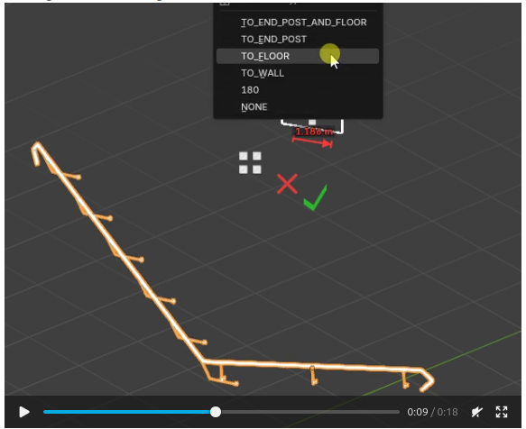
Testing the waters for a new "Extend orthogonally" gizmo to speed up creation of walls. Any feedback ?
^ Wow !
I did not expect this.
This was very helpful. Thank you very much.
I have overseen this completely ....
Proposal: make the LAYER2 parametric tools IFC-class agnostic
@Gorgious — picking up the thread from earlier, where I asked whether the wall gizmos could work on all LAYER2 objects and shared the model with wall cladding modeled as a LAYER2
IfcCovering. I dug into how the wall tooling is wired, and I think this is a smaller change than it looks, so I wanted to write up a concrete proposal.The key insight: the geometry engine is already class-agnostic.
The operations that do the real work — extend-to-underside, wall/wall join & miter, unjoin, fillet-corner rebuild — don't actually require an
IfcWall. They operate on three things every LAYER2 element has:get_reference_line),IfcMaterialLayerSetUsagewithLayerSetDirection = AXIS2(the vertical, wall-like case), andconnect_wall,regenerate_wall_representation, and the boolean underside clip all read placement + axis + layer set and write standardIfcRelConnectsPathElements/ boolean results. None of it inspects the entity type. Per the IFC4 spec,IfcRelConnectsPathElementsand AXIS2 layer usage aren't wall-exclusive either.Where the coupling actually lives.
The
IfcWallrestriction is only in a handful of gates, not in the logic:is_wall(gates the edit gizmo, panel, topology poll) andis_path_connectable_wall(gates join/unjoin,read_geometry, opening hosting) — both start withelement.is_a("IfcWall").is_a("IfcWall")checks (e.g. resolving which of a selected pair is the LAYER2 side in the underside gizmo).IsFilletCorner/FilletRadius) is stored on the wall-specificBBIM_Wallpset.The proposed change.
is_a("IfcWall")checks with "has AXIS2 layer usage (+ an axis)." A LAYER2 element that is drawn, edited and joined like a wall then is treated like one — regardless of whether it'sIfcWall,IfcCovering, etc.IsFilletCorner/FilletRadiusoffBBIM_Wallonto a class-agnostic pset (I usedEPset_Parametric), with a read-fallback toBBIM_Wallso existing files keep working — no migration needed.Who benefits. Anything legitimately modeled as a vertical AXIS2 layered element with an axis:
IfcCovering— cladding / siding (the original ask).IfcPlate/IfcMember— vertical panels: partitions, precast/SIP panels, spandrels (its StandardCase default is AXIS3, but vertical use is common).IfcBeam/IfcFooting— in some situations these class could be modeled as Layer2 objects... varying grade beam sizes, etc.IfcCurtainWall— when modeled as a single layered leaf (not as a member+plate assembly).IfcBuildingElementProxy— the generic catch-all.Explicitly not in scope:
IfcSlab/IfcRoof(they're AXIS3 — the targets walls extend to), andIfcBeam/IfcColumn/IfcMember(those useIfcMaterialProfileSetUsage— a profile swept along an axis, which is the separate "profile" parametric family, not this one)....
Here's a proposed PR that starts touching on this idea:
https://github.com/IfcOpenShell/IfcOpenShell/pull/8229
I left it as a draft, so it doesn't get built on BonsaiPR
...
This might be a good opportunity to make the following namespaces a little more agnostic, as well.
https://community.osarch.org/discussion/3503/layer2-agnostic-rename-candidates/p1?new=1 (edited based on @Gorgious's comment below)
The proposed PR above, however does not tackle this however.
Sounds good ! I think it should be separated in a different thread though as this goes quite beyond gizmo changes and is a real paradigm shift that goes to the roots of the codebase. Cheers
Cool, split here: https://community.osarch.org/discussion/3503/layer2-agnostic-rename-candidates/p1?new=1
Live preview for the array, love it!
Thank you @Gorgious