

What’s the core design intent behind Ramp Flight Tool & Duct Tool in Bonsai?

Hello everyone,
While learning to create IFC models with Bonsai, there are several tools that I have always found confusing:
When using the Ramp Flight Tool, it only generates a flat plane with thickness. I fail to grasp its purpose and underlying design intent. The same goes for the Duct Tool, which only creates a simple rectangular prism when operated. I would like to understand the original design goals behind these tools so I can use them more effectively.
Tagged:
Comments
Just an opinion - I'm not that closely involved or even an industry professional.
https://ifc43-docs.standards.buildingsmart.org/IFC/RELEASE/IFC4x3/HTML/lexical/IfcRamp.htm
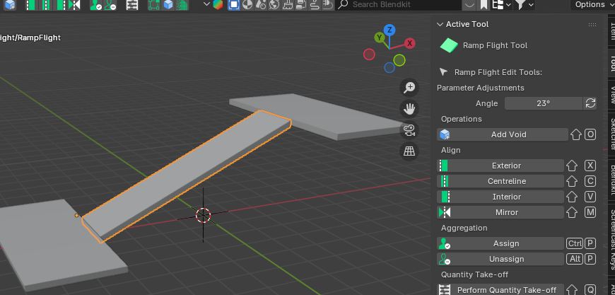
Bonsai and Ifc don't force you to stick to the suggested geometry. You can make a "ramp" out of any shape you can model (i.e. a wedge). Just create your model in Blender, then assign it the IfcRamp class. But when you look at the Ifc spec it is more about the concept of a ramp as a route between levels without steps... i.e. a flat plane angled to join two slabs on different levels. This is what Bonsai gives you by default.
Bear in mind that Bonsai is still developing. Some of the tools are still "here's something basic to get you started". I think the duct tool is one of these and the roof tool is another in that vein. MEP is one of those areas where the devs are still figuring out what the pros want/need in Bonsai. There are specialized tools for designing and routing MEP infrastructure. Adding fittings, junctions, automatic routing around obstructions, etc. IFC allows the representation, but the creation and editing tools are going to be in Bonsai. Those kind of advanced tools are a big job, and MEP has not seen as much interest and development. There do seem to be some nice improvements with some of the improved gizmo tools that Gorgios has been developing. Even that is not a full blown MEP toolkit though. It's a bit of a chicken-and-egg situation. Which came first? The tool, or the user?
Can I understand it this way: I can model a custom staircase shape by myself, then simply assign the correct IFC class to it, and Bonsai will establish all relevant associations between it and other components?
From my current understanding, I previously assumed that only geometry created via Bonsai’s native dedicated tools could carry relational links and attribute data. I’m not sure if this interpretation is correct. My vague understanding leaves me confused about the core purpose of these built-in tools—whether they exist purely to streamline modeling workflows, or primarily to pre-configure the full set of relational and property information for IFC entities.
@Fish_Little
as far as I understand you can have the monkey head as solid geometry and classify it as IfcRamp, add attributes, properties, classification
parametric geometry (which the monkey head is not) allows a different approach in creating (and updating) the object
Hope someone else will contribute to this topic, thanks
AFAIK from the docs the shape is correct, ramps are used to make different levels accessible to people with walking disabilities or with strollers, or anything that has wheels I guess, like carts in a factory.
Bonsai gives you the most basic shape you can use to make the ramp, but currently there is no UI per se to let you select a starting point on floor 1 and a landing point on floor 2. You can modify the slope with the Angle parameter in the element properties panel. I think as many tools the goal was to build the very first building blocks for authoring these entities but it does require an awful lot of manipulation which makes it unusable in practice on a real world project. But the infrastructure is there and anyone can jump in the code and improve it, Bonsai being open source and all.
Cheers
Yeah. The ability to select two slabs with the ramp tool selected and hit Shift+A and have it make a correctly aligned ramp at the cursor would be a really nice added feature. Maybe with some gizmo action to position and manipulate the width. I wonder who's really good at that sort of stuff.

I think it would be good if you could switch between stairs and a ramp. It’s just an idea.
Stairs and ramps have very different gradients. Here in our Blighty Building Regs our stairs bottom out at 27° and ramps max out at <5°. Sure it's going to be hilarious watching people in wheelchairs screaming down a 35° degree incline, but not very functional.
@sjb007 as you correctly highlighted through humour regulations need to come first before developing useability for ramps, stairs and handrails. I made an N-Panel addon to calc the geometry for stairs solely for NZ Building Code.
While we can use the gizmo for stairs manipulation, which is fun, but stairs (and all) are regulation driven designs and they need to be constrained by those regulations
FWIW regulations can be integrated in the gizmo system. It can support increments, min and maximum value for risers, etc. The problem is that regulations vary from country to country, and even in a single country may vary from region to region. does anyone know if there is some kind of generally agreed upon format or document for this kind of regulations ? How do other BIM authoring softwares deal with that? do people need to build their own libraries with these in mind ?
Hi @Gorgious
Stairs are a little passion of mine so I'm modestly confident that I can answer the 'generally agreed upon format' question, my answer is 'not really'.
Some countries use the 2R+G formula and others use a stair pitch angle as the first calculation, basic stair geometry. Then there are classes of stairs, in NZ there are 4, from a service stair through to an accessible stair, each class can have different mins and maxs for tread length, rise, nosing (and nosing profile), clear width (between handrails/wall), the in the case of accessible stairs is the total max rise before an intermediate landing and max gaps between treads. Then there are the handrail and ramp design rules.
I have only worked in architectural roles in Australia and New Zealand where the rules vary, so I imagine every other country has suffered uniqueness bias and made their own slightly unique rules too :)
I would start with an option 2R+G or Pitch angle. Then choose classes of stair being designed and that would then direct to a lookup table for tread depth, rise and nosing dims. We users could provide our local data for the lookup tables.
@Nigel You maybe have it too, but we also have minimum head height, special cases for height under eaves, max steps per flight before a change of angle, minimum size at the narrow point of a tapered tread, and on, and on, and on. Loads of fun! I think the X < (2R+G) < Y is a fairly common "comfort guide" which we (UK) have too, but limited also by min/max rise/going. You would need a pretty smart core that could use country specific criteria files (even code) to restrict all these parameters.