

1st August 20:00 UTC Monthly Meetup

The next meetup will be on the 1st of August 20:00UTC (8PM) (i.e. the first Saturday of the month).
This one's main presentation will be by @topologic about ... well, Topologic :)
We're always looking for volunteers to give a short minute presentation or demo about any cool open source related thing :) You can talk as short or as long as you want! Or, if you'd like something to be talked about, please also suggest it! The meetup is held on the first Saturday of every month.
Please see the wiki to add your topic: https://wiki.osarch.org/index.php?title=Monthly_Meetup
If you're up for it, add yourself to the spreadsheet and if you add your email too, I'll send around a reminder email prior to the event:
https://docs.google.com/spreadsheets/d/19EzmthOp5hGYFTZCgOIm51n7hvcp_F8nB_XLYeTJ0zU/edit#gid=0


Comments
Wondering if Marcin Jakubowski of Open Source Ecology would be a good fit for giving a presentation at one of the future monthly meetups to talk about how OSE makes use of FreeCAD (amongst other open source tools) as a baseline for their R&D and design sprints. They even have customized workbenches for iterating on their 3d printer models and other machines being developed as part of their Global Village Construction Set. He would most likely also want to talk about their Extreme Enterprise Event (reminiscent of the open design project once mooted on this forum) being planned for next year, and for which I know he's shopping for collaborators.
That's a fantastic idea! I also have Vi-sense looking to talk about their tool on IoT sensor visualisation. @DADA_universe would you mind reaching out to Marcin?
Sure, will do so. Which month should I ask him about though?
@DADA_universe how about October? August is @topologic , September could be Vi-sense (haven't 100% confirmed).
But as always, we should invite him to join these forums and see how we can collaborate further with him. We maybe able to develop tools to help his work (which is absolutely amazing, by the way)!
Great, sent him a mail, will update us here once he gets back.
Still without proper internet this weekend.. i don't think i'll be able to join :_( but really interested in @topologic !! will watch later when possible
He's confirmed for October (3rd) and would be joining the forum. It would be interested to see how OSArch's software base cross pollinates with OSE's focus on hardware.
Thanks so much @topologic for your presentation!
The presentations are now available on Peertube: https://peertube.social/videos/watch/e8173fef-5d26-4d8b-98c2-400b095f9c81
It has also been mirrored on Youtube:
There was some discussion after last month meeting about Space in forum. I tried to provide some connection in Arch Space in FreeCAD, but apparently I am far from having competence, programming skills to do that :(
There are lots of questions from the Topologic presentation. Maybe I post a very simple FreeCAD model here and see if somebody can somehow 'translate' into Tolologic kind of model to see how things can works (instead of asking probably piecemeal questions) :D
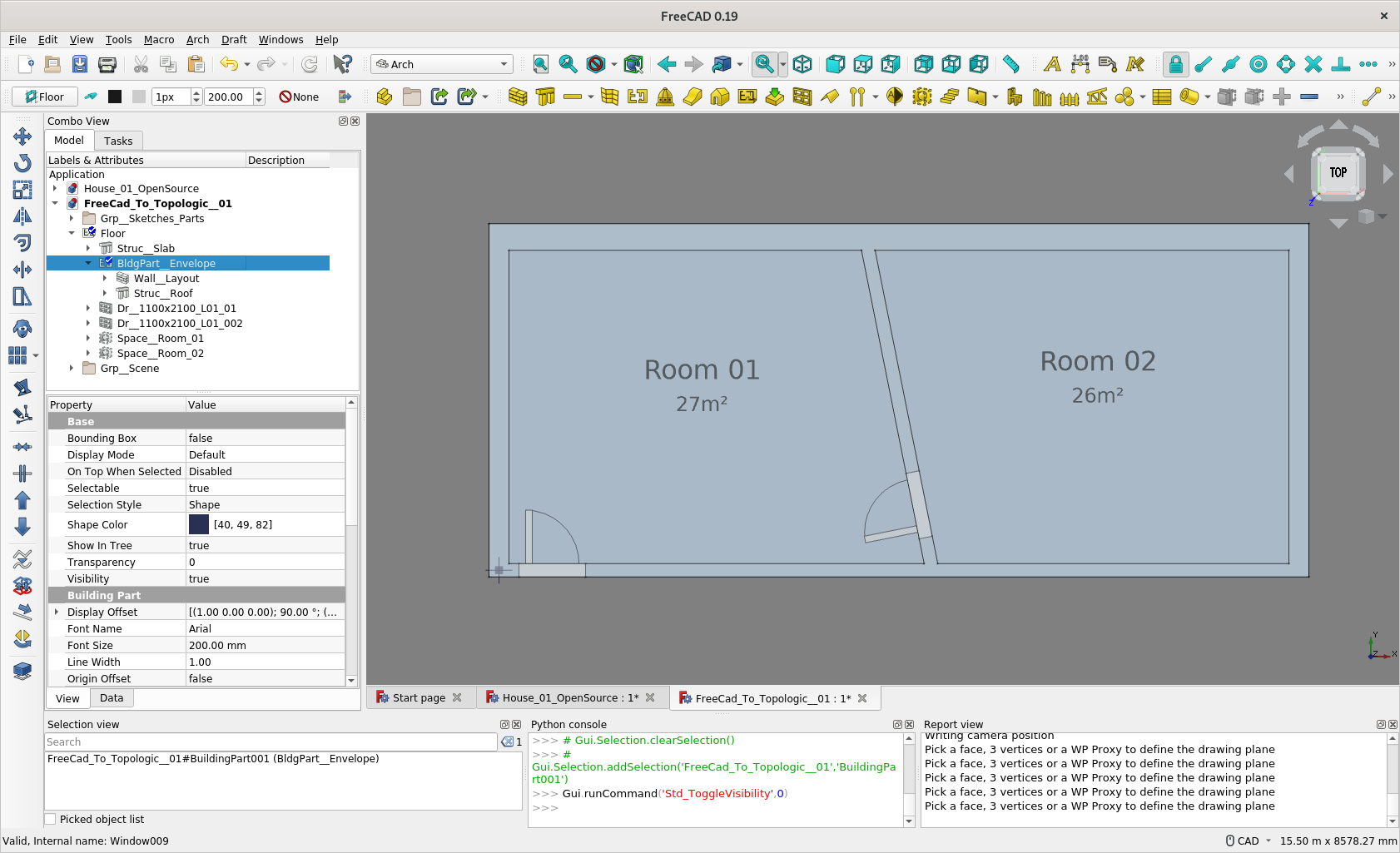
Simple Model as follows:-
1. ArchWall object with 4 external walls - various thickness
2. 1 internal walls
3. compose 2 ArchSpaces
4. 2 Doors / openings
5. 1 slab, 1 roof
(Somehow *.FCStd format is not allowed to upload, shouldn't it be allowed ? - pls rename the attached *.zip into *.FCStd to open in FreeCAD)
FC and IFC files attached
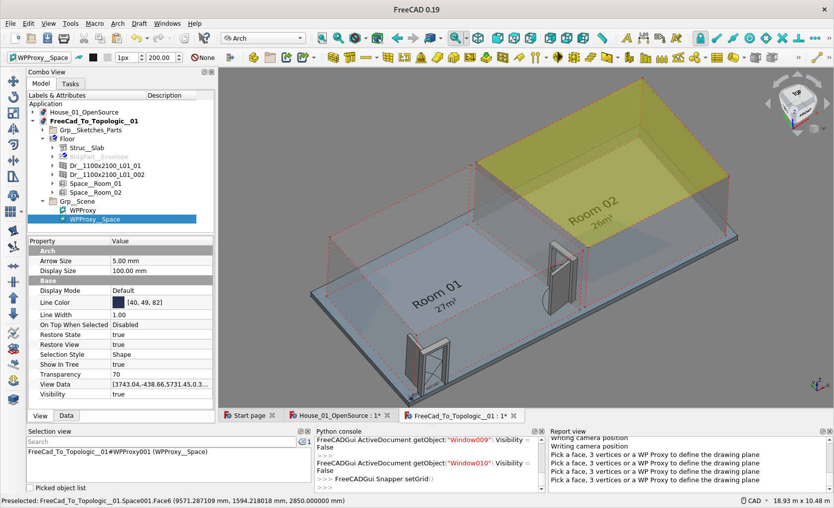
I can somehow in FC, make the ArchSpace 'know' e.g. which doors and/or windows etc. are in the rooms. But no idea further e.g. as to how to further to establish relationship -
or better still
etc.
Thanks @paullee. I will try to load this. But perhaps a better route is Topologic2FreeCAD. Topologic would create the conceptual masses, conduct all sorts of analyses and when ready, you can ‘thicken’ the model by converting faces and cells into walls and rooms etc. A far more reasonable and straightforward approach imho.
Hi @paullee. So the model you created imports perfectly into Topologic. This is not surprising because FreeCAD and Topologic both use OCCT and the BREP file format. The issue here is not geometry, but topology. The two voids/spaces are a good start, but they are separated by the walls. I had the same issue with models coming from Revit. I overcame that because you can embed room information in the doors. So I can do a bit of logic to find what rooms are connected by what doors. Is that possible in FreeCAD?
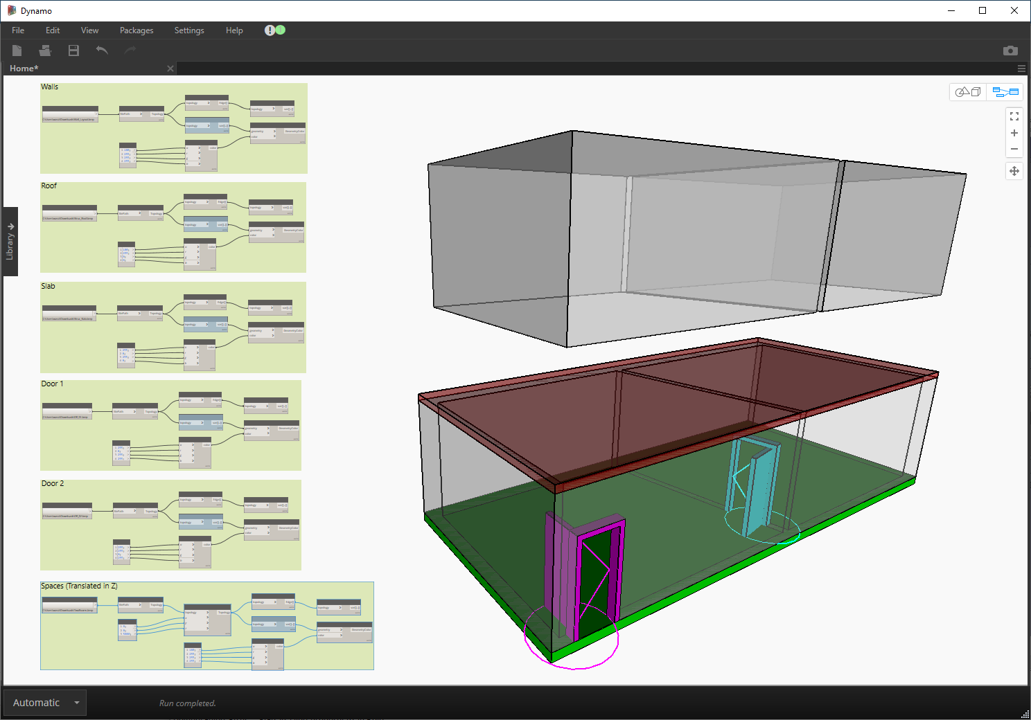
@paullee. Now by importing the ArchSketch_Layout and a bit of python, I was able to fairly easily build the correct CellComplex. From there, you can calculate the dual graph and ask it to go through shared topologies for example (so two edges, three vertices) or through shared apertures (like the door). I had to thicken the door and instersect it with the faces of the CellComplex to get the face of the door that belongs on the shared surface.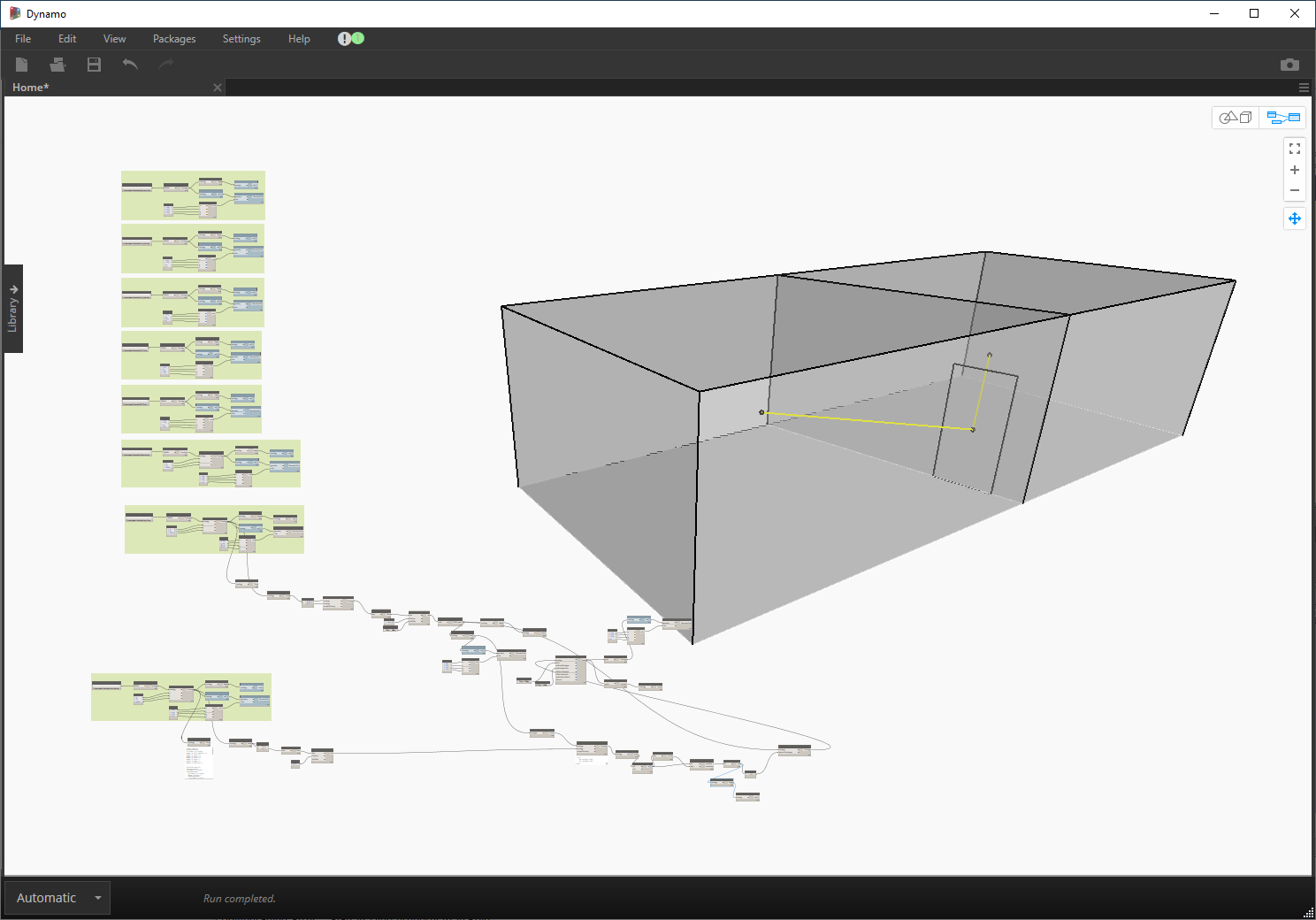
... The two voids/spaces are a good start, but they are separated by the walls. I had the same issue with models coming from Revit. I overcame that because you can embed room information in the doors. So I can do a bit of logic to find what rooms are connected by what doors. Is that possible in FreeCAD?
@topologic
That's 1 question out of many :)
ArchSpace has a Group attribute, I put the Door connecting to each of the Space.
2nd Question
Updated FC model attached
BTW, there is Dependency Graph in FC, but this kind of topology is not Spatial :)
You can find the Space relationship with Doors, with some efforts :D
This picture looks perfect ! If it could be illustrated by way of graph, that would be awesome too !
Then, 3rd Question -
@topologic
4nd Question (last atm :) )
A bundle of thoughts / questions :D
Thanks.
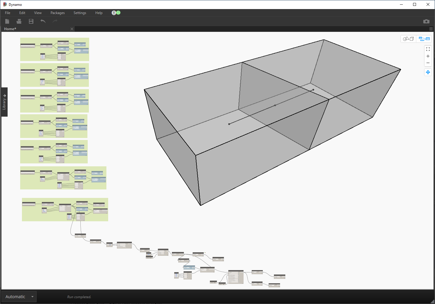
Thanks. The important thing here is that it is a true graph. The yellow lines are basically asking the graph to draw itself. So yes, the data structure is all there.
It is not 'editing' in the tedious manual sense. The dynamo script will re-calculate and update once the input changes. What one needs to be careful about is that the spatial operations in the workflow are generalized and adaptable to different inputs. So, for example, if you changed the location of the door in FreeCAD, the script will still work and create the new graph automatically. This is why so many architects are enamored with visual data flow programming software like Grasshopper and Dynamo. Once you invest the time to setup the parametric and spatial workflow, then you can run hundreds and thousands of iterations and you can search the solution space for optimized results using things like evolutionary algorithms.
As I said, going from complex static BIM models to conceptual and inter-related topologic models is really backwards. We need to change our mindset. The same way you started with a conceptual sketch and build it into a complex 3D model, I am suggesting the one should start with something like topologic where it is conceptual and inter-related lightweight, but rigorous model. That topological and spatial information should stay in the model as you derive more complex building fabric, structure, MEP models from it. A change in the conceptual model would then cascade into changes in the derived complex models. This is why I am advocating a Topologic2FreeCAD rather than a FreeCAD2Topologic.
I am trying to stop myself from asking too many Qs atm, just want to say so we can do something like below (quoted by brunopostle) ! Thanks !

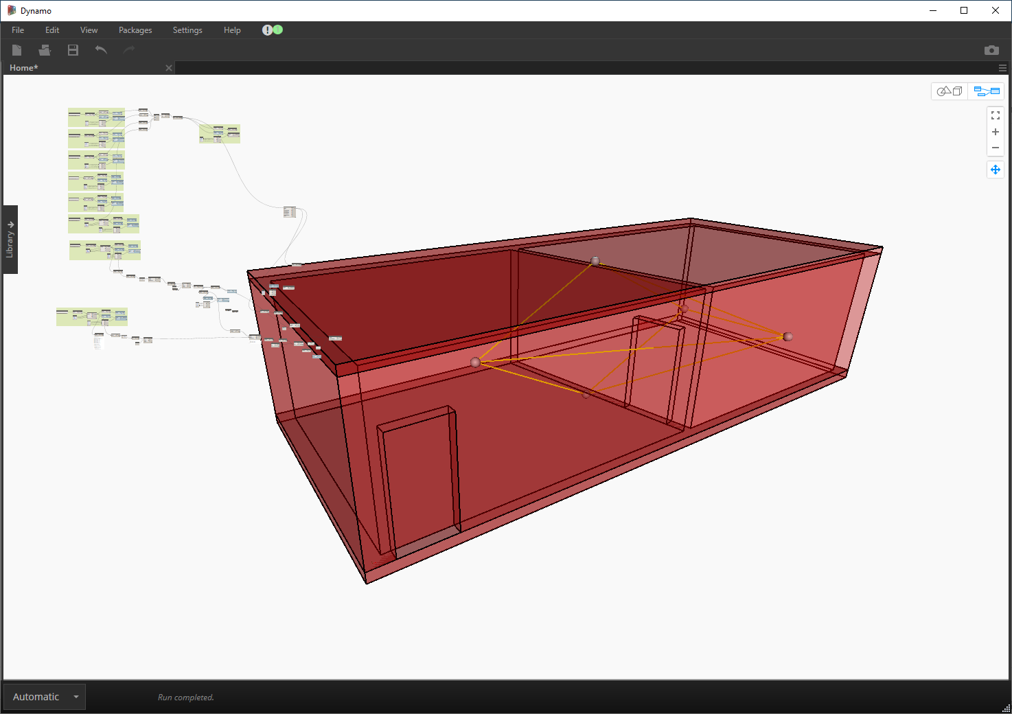
It is a long-standing issue that Revit struggles with as well. If the designer does not add 'Conceptual Spaces' and Room information, then the model is simply a building fabric model. Topologic does not care if it is a conceptual model or a building fabric model. It will still try to build a CellComplex and the graph can be derived as you see below. But in this case, the graph is connecting: Slab Cell <--> Wall Cell <--> Roof Cell. There is no conceptual space. Now if I add the two conceptual spaces to the mix, Topologic connects those as well.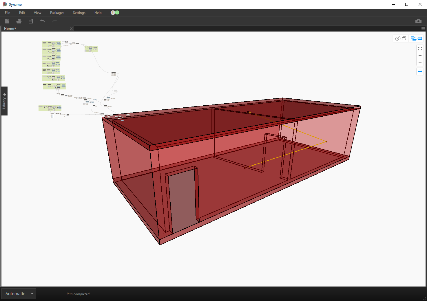
m trying to stop myself from asking too many Qs atm, just want to say so we can do something like below (quoted by brunopostle) ! Thanks !
No worries. Happy to answer all your questions!
The short answer is: Yes. I have to dig it up, but at one point, I wrote a python script that creates a 2D graph drawn from a Topologic Graph. But my point is, you can simply get that data out and feed it into a graph automatic layout type of software to draw these for you. What is important is that you have the data.
Just a note / reminder here -
Yes.. the wall was modelled in FreeCAD as one solid. So, Topologic is not going to be able to see it as 5 walls on its own.
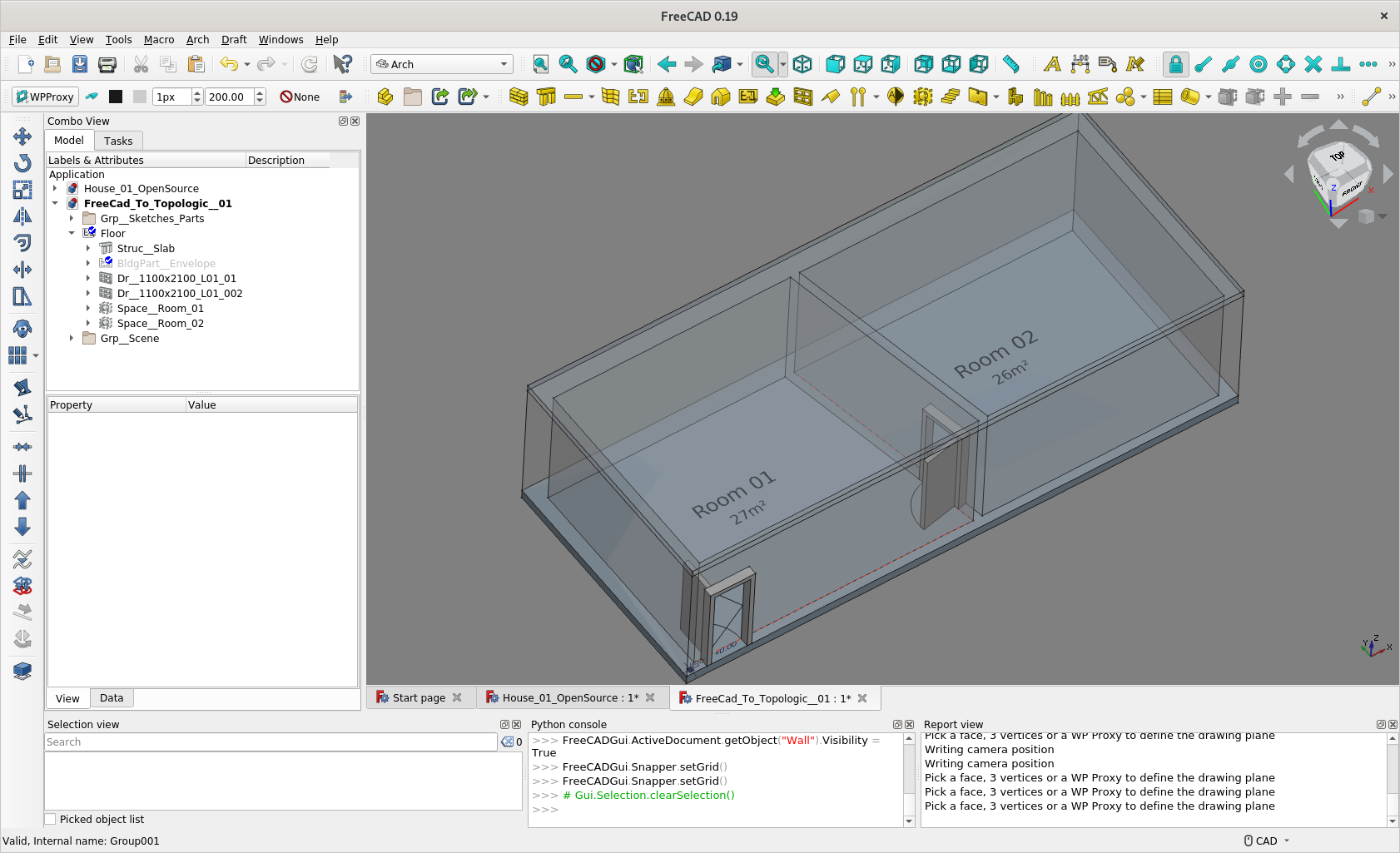
The reason the rooms were not identified is because the walls had holes in them for the doors. So the space leaked to the outside. If you modelled the doors as closed, then Topologic would have automatically derived the interior space as a Cell as you can see below.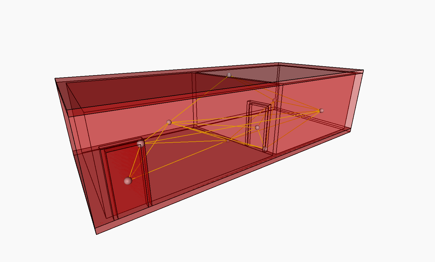
@paullee . Here is the 2D graph automatically generated from a CellComplex
Interesting, so I have the doors closed in model below, without the ArchSpace :)
Good to see if it works.
Wondering what workflow should be better. Hope more peoples can shed some lights here ?
I think this thread shows exactly the pitfalls of trying to go from a BIM model to a conceptual model. One possible solution perhaps is to look at the spatial relationship information (if it exists -- eg. this door belongs on Wall A and connects room B to room C), and largely ignore the idiosyncratic geometry (but I don't yet see good ways of doing that). You can probably build the conceptual dual graph, but the actual CellComplex might still fail.
This approach will always have caveats and sources of error. The truth of the matter is, BIM models such as the one above are not created from a conceptual point of view. BIM software does not require nor impose restrictions on spatial relationships. Nor does it have the depth of implementation to focus on more important spaces and ignore or trim away less important ones. I believe it is a losing battle. There will always be those who will tell me, "but I have hundreds of BIM models that I want to analyse." Sadly the solution will be bespoke and imperfect in many cases.
I am not sure what architects feel about the Topologic2FreeCAD route, any comments :)
I am thinking a workflow this can be done somehow efficiently in FreeCAD :-
To this end, a few issues maybe worth further discussion :-
Hi @topologic, I try to do some mock-up of Spatial Order to BIM workflow, see how it sounds to you.
1. With ArchSpace Only
- To start with, there is no ArchWall, Slab, Roof etc. Just 2 Spaces and 2 doors (maybe some kind of 'Connection Object' instead ?).
- As the final ArchSpace represent the void of the room at later stage, 2 'adjacent cells' do not share a common surface - querying adjacent cells in Topologic may fails ?
- Apparently, this workflow does not make use of the Topologic.ByGeometry in general
- Door/Connection - - - Room 01 - - - Door/Connection - - - Room 02
2. With Geometry of 2 Cells
- There is only a compound of shells / surfaces forming 2 'Cells'
- Apparently there is no ArchSpace - only pure geometry - have no idea how to put no semantic meaning e.g. room names for the 2 Cells
- And have no idea how to put a Door / 'Connection' between 2 Cells
Thanks
Hi @topologic
Have attempted another workflow that streamline the generation of the 'CellComplex' suited for Topologic Workflow and the general Architectural Worflow.
Now, can have ArchSpace which share common surface between adjacent Rooms - just like the CellComplex
The ArchSpaces are now created just like a Conceptual Volume - not the actual void of the rooms, so the volume does not represent the actual physical room.
[re-post file]
Latest FC model and discussion in FC forum
There is a discussion in FreeCAD Forum, hope it would be done :D