

2D drawings in dwg from IFC files

I have been following the developments of Blender BIM with expectation and high hopes.
One milestone for me as an architecture in design mostly, is the production of 2D drawings for the communication with colleagues and permit procedures.
Apparently there is work in progress (?) in this direction by the Blender BIM team, but for now the output of 2D is SVG: vector for cut entities and fonts for annotations, but also raster for rendered objects past the cut plane.
This is not a workable option for me.
So I searched and found an app, it's free, funded by a research group in Korea, it does the job of cutting plans, sections, elevations and details, from 3D IFC models and outputs .dwg
Product page: https://www.inno-lab.co.kr/Home/en/product-KBim_D-Generator.html
Video demo: 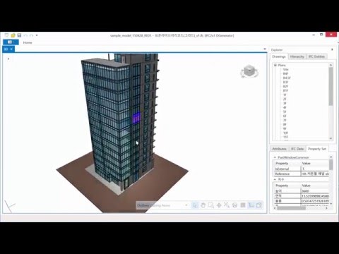
Email contact: [email protected]
I did some quick tests, it does what it says with it's matching sample IFC file and with a sample IFC I downloaded from OSArch. It dates back to 2016 though and there does not seem to be active development.
If others want to try it also and give feedback here, please do.
If the Blender BIM team is interested, maybe they would share code? it's a research effort.


Comments
I am also very interested in this workflow. IMO 2D plans are and will stay a de facto output format since they're the easiest way to parse information on site both in construction phase and in design phase. Acad while severely outdated in terms of features & BIM operability is still widely used by pretty much any business I work with. Thanks for sharing !
Regarding the BlenderBIM addon, I've found the process to copy from svg to dxf is pretty straightforward since there are some builtin python libraries to parse svg files which are just xml files under the hood, and the ezdxf python module makes creating dxf (at least simple ones) really easy. We just need a bit more granularity in how classes are defined and exported, in order to create meaningful layers in the dxf file. AFAIK this is on the roadmap and the drawing creation process is heavily improved day by day so I don't think we're that far off from a straightforward Bbim > dxf export.
Hi,
Would you kindly elaborate what are these python libraries and how I load to use them?
Also important is that annotations are text entities and not glyphs and that dimensions are dimensions and not lines and text, at export.
It would be wonderful if the .dwg entities could be layered by IFC class, as you also suggest.
The Korean app has some of the above funtionality: text and dimensions are good and dimensions are generated!
All dwg entities are placed on layer 0
The interface is nice in that it allows you to setup choices for export in an interactive way. I guess this could be done with classes directly from the IFC/Blender BIM file, where one can work on choices of section planes or detail areas.
LOD (level of detail) is another item to "granularize" so as to be able to get back detail appropriate to the scale and intended scope of the detail.
You can use minidom to parse svgs. See https://stackoverflow.com/a/15857847/7092409
Of course I should have added that you need to know your way around coding with python, at least at an entry level. Nowadays you can do a lot of things with chatGPT and the like but I don't think you can get that far with it. All the information about text and transformation, etc. is written in semi-human-readable format in the .svg so it's "just" a matter of translating it into dxf format with ezdxf.
I haven't dabbled into dimensions yet but I don't see why it shouldn't be possible to translate them as well, although I don't know if a 1:1 roundtrip is possible since dimensions are kind of an abstract construct to represent the physical dimensions of an object, so they may be implemented differently in different softwares.
Is this a vague impression of coming developments or is there an actual roadmap with a timeline?
Is there a location on the osArch site or Blender BIM site with an outline of goals and milestones?
This is the closest thing BlenderBim has to a road map:
https://github.com/orgs/IfcOpenShell/projects/4
Its the goals/to do list for the next stable release of the addon
Well to be honest this is a statement based on the rate at which commits specifically regarding drawing output are coming in by the osarch devs and a recent dicussion on the OSArch chat. See for example https://github.com/IfcOpenShell/IfcOpenShell/commit/b6caf069d06fb159a991929cc788a7131b4109ae which came in yesterday. I don't know of a specific timeline though, the development tends to be kind of project-driven in terms of features and bug fixing like many open source projects.
See for instance the community project which you can follow there which already uncovered and helped fix a significant number of bugs or QOL improvements.
I think @aothms is aware of this research effort. I think it would be great to reach out and have a chat. The video looks incredible, and there are lots of things they seem to do so effortlessly that we seem to struggle on, like the rapid generation of the views. I'd love to know what @aothms thinks are the main differences between our approaches.
@csimeon I think you might have outdated information.
This isn't quite right. We support complete vector output for everything - both cut objects as well as items in the background / projected elements. In the early days, we used raster backgrounds, but that was a long time ago. We still offer a raster underlay, in case you want detailed renders as a background too underneath the vector linework, but that's optional. Are you sure you've tested with a recent version?
We also do support DXF and an auto conversion assuming you have the libraries installed and insert the appropriate command in your BlenderBIM Add-on settings. The auto conversion isn't the best, and the best approach is a dedicated DXF writer so that we can use layers properly and so on, but that's unfortunately not yet built. Here's an example of a DXF:
Here's the real time view of the infamous Revit sample project, and below you can see a 100% vector cut from it (in this case, no annotation present). The real time vector cut takes about 1 or 2 seconds or so, then is instant and real time as you can see in the GIF below. I suspect this performance is similar to the Korean application. If you create a drawing from it, the drawing vector cut takes 12 seconds on my machine (8 seconds if doors had a PLAN_VIEW representation). (I suspect in the Korean application, they auto-generate door swings, whereas we leave it to the user to decide whether they specify 2D view-specific representations or leave it as full 3D). 8 seconds isn't great, but it isn't terrible either considering that sample model would be considered a medium size project.
I don't know them, nor their approach. I don't see hatches or fills in their sections. For mesh-based hidden line rendering, the performance looks about right. In our case it's mostly the geometric detail (detailed door knobs, fixtures, etc.) that blow up computation time. A well-prepared model even in our tooling can be drawn quickly. In open source software you often end up with a modular patchwork of independent tools, as opposed to a monolithic centrally developed application. In our case that means quite a bit of translation of data from Open Cascade (HLR) to Python (wrapper) to CGAL/Geos (2d cells) to Python to Open Cascade (ray-tracing for semantics of cells). Performance may suffer because of this, but each patch of software can and will be reconfigured, reused, replaced and maintained individually. It's a bit of a developer-centric way of working but ultimately also results in a much higher degree of freedom and control for end-users.
I have an error installing software. Microsoft.SemanticKernel.Agents.Abstractions.dll