

Blender object to IFC object > mess of vertices, edges, faces

I did a model of a part of a door lock in Blender.
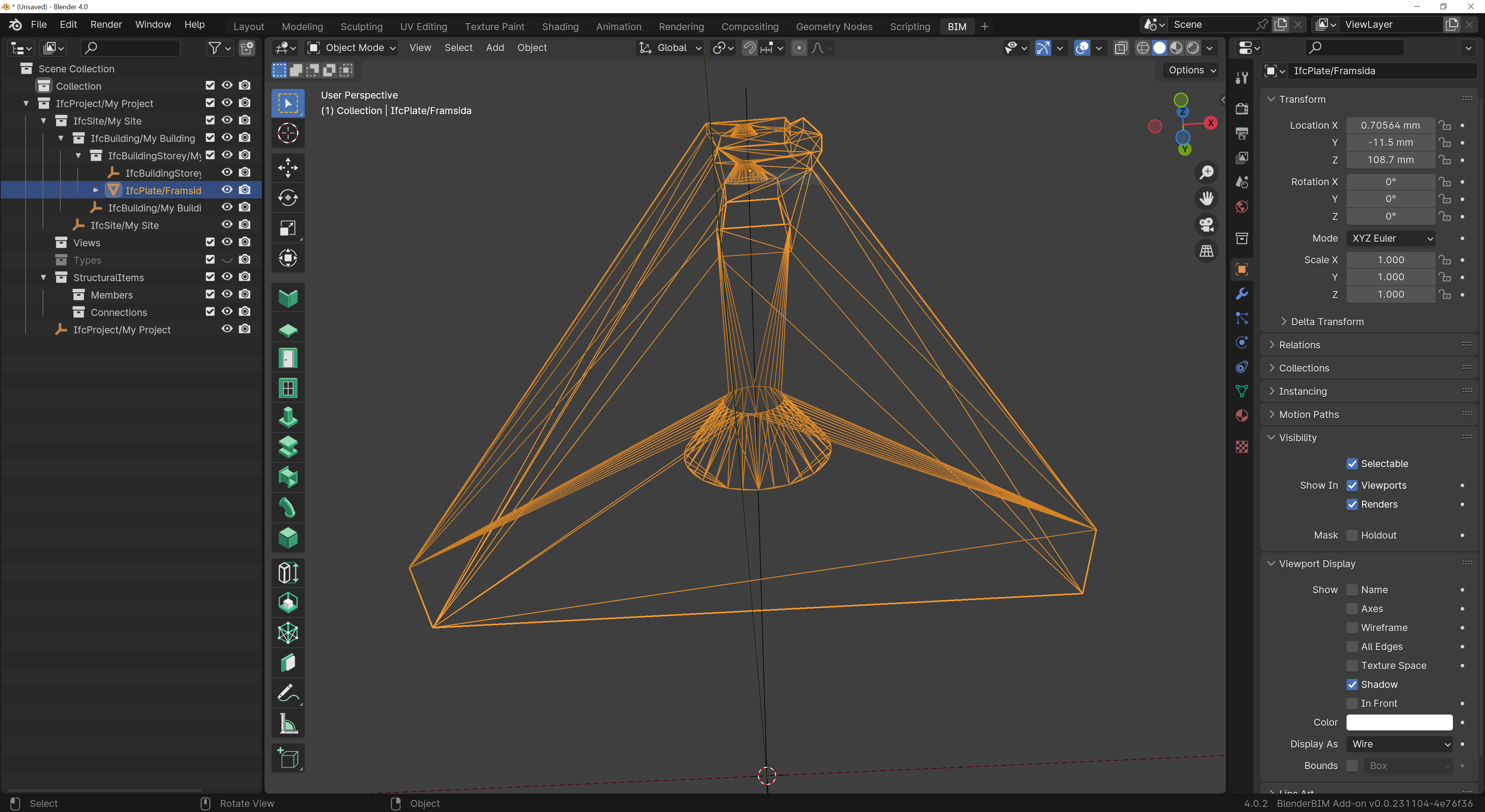
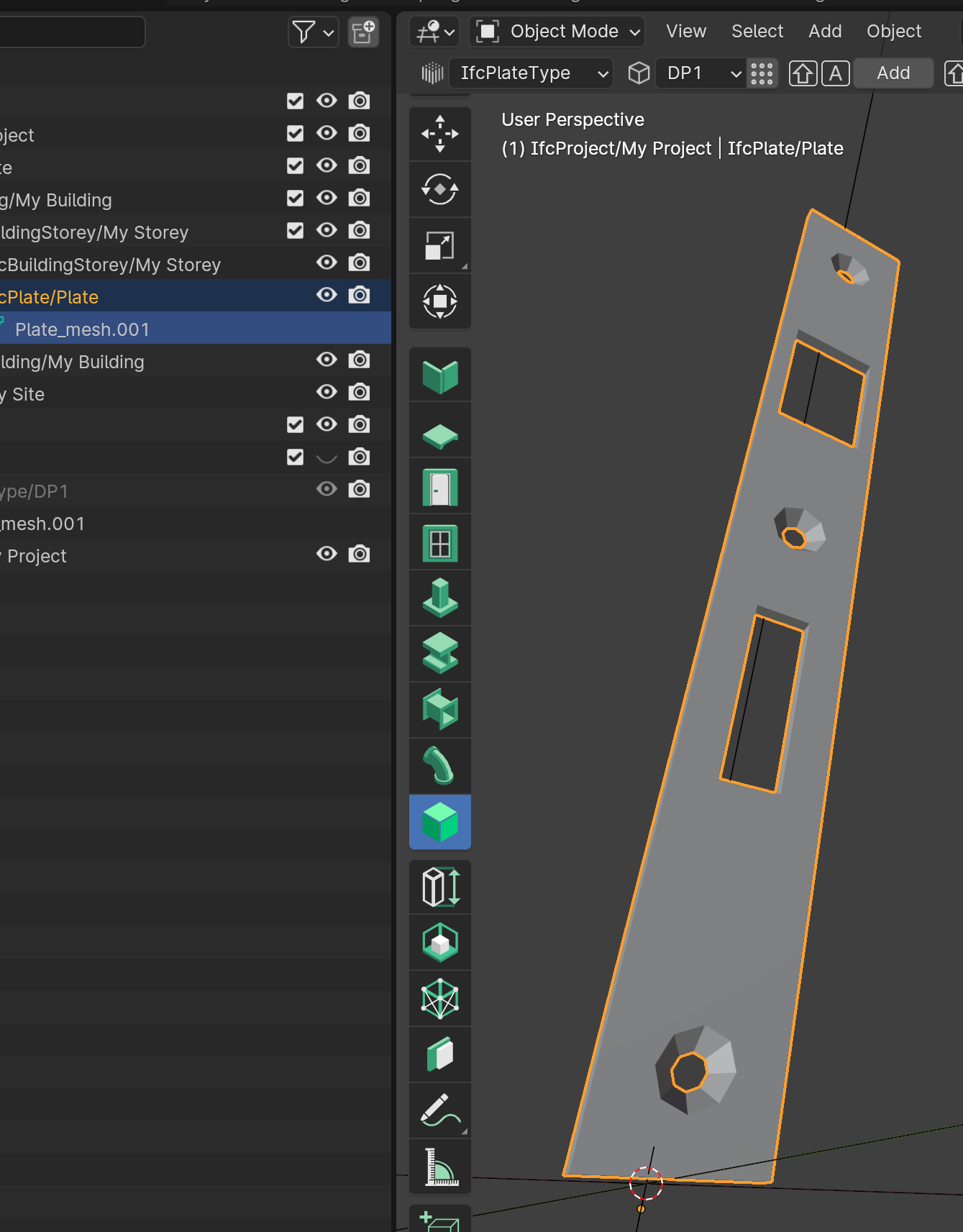
I created and IFC project in BlenderBIM - and created an IfcPlate object from the Blender object. See below.

Then I saved the file as an .ifc-file, and as a .blend-file.
When I open the .ifc-file - vertices, edges and faces is a mess. See below.
But when I open the .blend-file everything is just fine, just like a made the model.
Why does the .ifc-file create a mess of my vertices, edges and faces?
Tagged:
Comments
Here are the files.
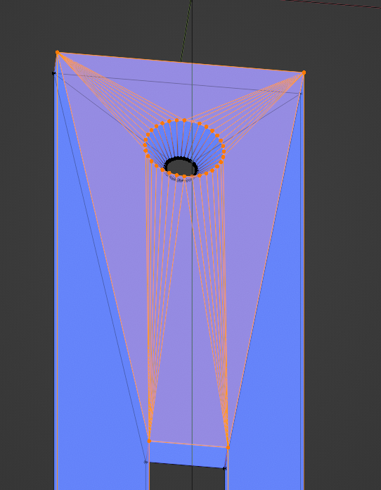
Hi @martin BBIM has triangulated your model, see result when a Triangulate modifier is applied by Blender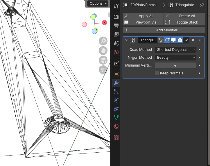
I opened the Blender file and found a couple of odd bits of Geometry, a face one 3 different planes and the screw holes were not cut through. I don't know how forgiving BBIM is with these things :)
Taking a step back, your original Blend geometry is pretty messy, it has coplanar intersecting faces.
Despite this, what you're experiencing is not a bug. For visualisation, IfcOpenShell will always load a tessellated, triangulated form of your object, regardless of the original geometry description (e.g mesh, solid, etc). This is purely visualisation: e.g. if you have a circular extrusion, it will be faceted in Blender because Blender uses meshes, but it doesn't mean that IFC has faceted your extrusion - it's just the representation.
If you try to edit it, however, it will show you the true underlying geometry. For example, if you press tab to enter edit mode, you will see your ngons again.
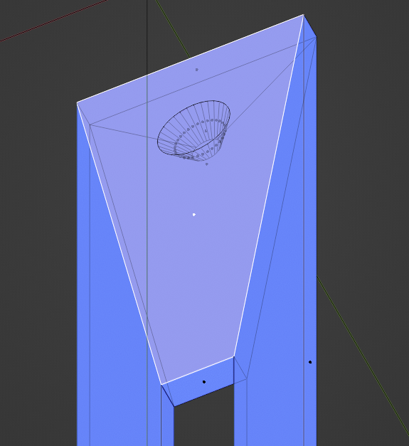
Your mesh appears kind of fine in the viewport in wireframe view but really is not. It is non-manifold which will make your life harder when you try to visualize this element. A few of the notable problems, and suggestions for "good" mesh topology
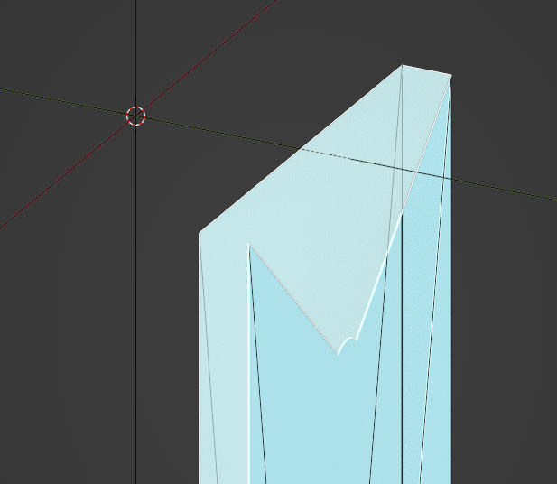
All vertices of a face should rest on the same plane in 3D space, to avoid weird deformations. At the basic level all rendering engines see triangles, so your mesh will be triangulated no matter what you do. If all vertices lie on the same plane, it doesn't matter how it is triangulated, since there will be no visible seam either way. Otherwise the visual result of the triangulation will depend on the rendering engine and the triangulation algorithm. eg this face will 100% give you problems
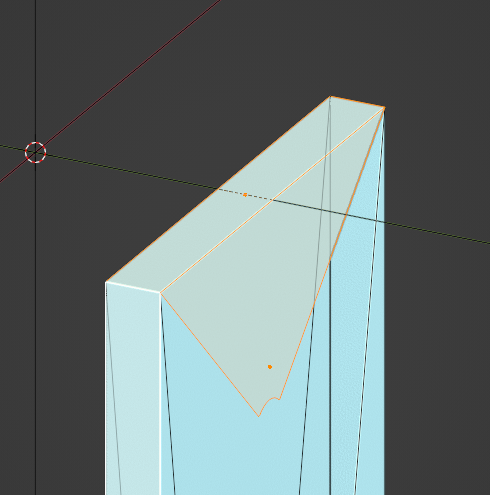
And how you can fix it. Select vertices which should host and edge in edit mode and press "J" to join them.
There is a non-manifold face in your circular hole that will mess up visualization. You can just remove it
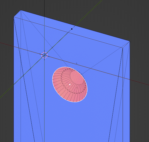
The holes are covered by bigger polygons which makes them non-manifold. Delete them.
Here instead of pressing F when the hole vertices and the polygon are selected, press F3 and type "Bridge Edge Loops". In Blender a face can't have a hole in it, that's why the mesh is triangulated like so.
If you really want to create a clean mesh, that will deform well under subdivision or animation, I really suggest you read more about "Quad Based Workflow", there are a ton of ressource about it online.
Note I think ideally if you're going to use the IFC schema you would model the body of your object and punch holes with the void tool using BlenderBIM. That way you let ifcopenshell decide how the topology of your object looks like.
Cheers
Thanks for the feedback. I had to learn some mesh modelling in blender. With the new mesh it works just fine.
Congratulations, this looks like a great mesh ! Cheers