I´ve created a beam in BBim, saved it, then I opened it in FreeCAD. Copy and pasted it into a new file. Created drillingholes in partdesign (saved it as .step) and did the GCode generation for milling in the pathworkbench. The possibilities are great and amazing for me.


Comments
Could you outline the workflow here? And try Native-IFC in FreeCAD and see the possibilities? :)
In BBim I copied a beamtype, then i manupulated the profile and used a reactangular hollow profile with radius in and outside. This type I have added as object to a storey (so it's visible). After saving as ifc I changed to FreeCad. There (bim workbench) I selected in the tree only the beam. Pressed "Strg (ctrl)+C" created new file, there I pressed "strg+V". Saved this as .step. Opened the partdesign workbench, selected the beam, and used "create new part". I've created a scratch, closed it, and attatched it to a face. Then I opend the scratch (because the zeropoint is in the center its possible to do a nice job) and did the drawing. Closed it, used the "drillinghole tool". Saved that and changed to the "path workbench". Created a new job, did the config (there are vids on yt) and used the spiral tool. After that I did the Postprocessing....
I like it because of the workflow and there is no triangulation also the defined radius in the profile is perfect, thats the amazing thing for me (so it's possible to use the metal structures of .ifc and do the milling and mechanical stuff in other programms and formats.) I like BBim 😀
Inspired by your workflow, I tested a bit of FreeCAD Arch Structure with a universal beam type and roundtrip IFC ... seems can skip the 'step' part :)
(rename the attached filse to remove the '.zip' to become FC file to use)
Hi Paullee,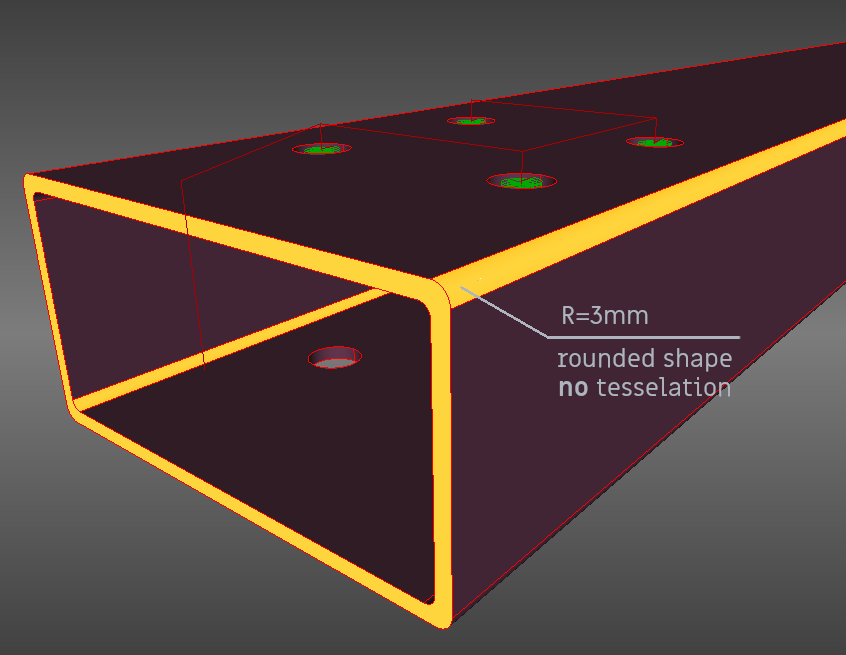
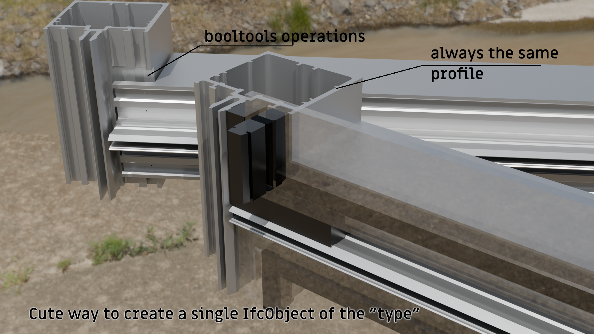
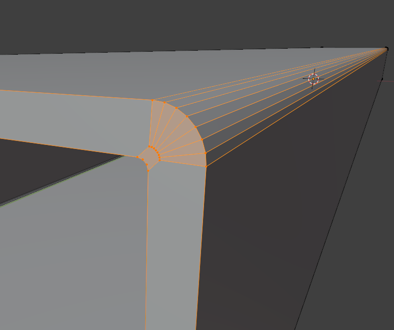 thats the way, how the corners normaly tessellated in .ifc, used as an object (without using profiles that are described as "code" and used for creating "beam-types")
nice... but my point is the tessellation of the faces in the corners, take a look at the screenshot...
https://standards.buildingsmart.org/IFC/RELEASE/IFC4/ADD2/HTML/schema/templates/body-tessellation-geometry.htm
Thanks, I added arc to the profile, and tested to export to IFC and re-imported again. Seems the arc is not tessellated, check ifc to verify.
#44=IFCTRIMMEDCURVE(#43,(IFCPARAMETERVALUE(90.)),(IFCPARAMETERVALUE(180.)),.T.,.PARAMETER.);#45=IFCCOMPOSITECURVESEGMENT(.CONTINUOUS.,.T.,#44);#46=IFCCARTESIANPOINT((0.0032,-0.0644,0.));#47=IFCCARTESIANPOINT((0.00320000000000001,0.0643999999999999,0.));#48=IFCPOLYLINE((#46,#47));#49=IFCCOMPOSITECURVESEGMENT(.CONTINUOUS.,.T.,#48);#50=IFCCARTESIANPOINT((0.00920000000000005,0.0644,0.));#51=IFCAXIS2PLACEMENT3D(#50,#41,#6);#52=IFCCIRCLE(#51,0.00600000000000002);#53=IFCTRIMMEDCURVE(#52,(IFCPARAMETERVALUE(180.)),(IFCPARAMETERVALUE(270.)),.T.,.PARAMETER.);#54=IFCCOMPOSITECURVESEGMENT(.CONTINUOUS.,.T.,#53);Hi Paullee,
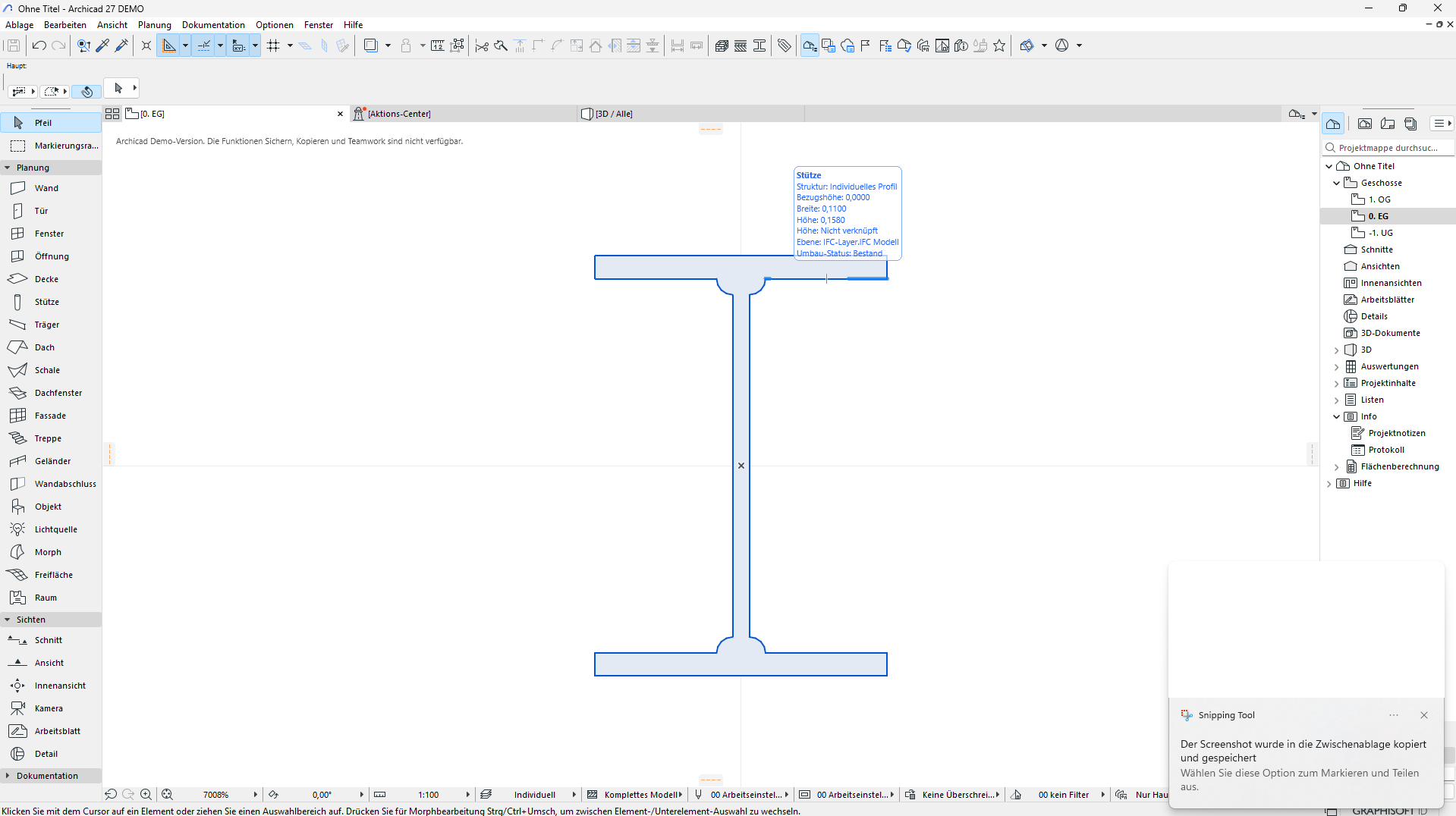
thx for your reply (like it)... Looks very nice... for your Info: I´ve opened your beam in blenderbim (there i couldn´t change the length), did the same in Archicad (you can download ArchiCad27 as Demo without licence - but you can´t save) there it looks a little bit strange, but I could change the length.
In BimViewer "BimVision" it looks great, also in FC. Attached my ifc beam created in bbim
Greetings
So the 'internal' curve get 'inverted' in ArchiCAD, but not BB, BimVision, right?
And it would be great if BB can change the length - maybe pinging @yorik (the Core Developer of FreeCAD, Arch/BIM/Native-IFC/Draft WB), if he is interested to have a look, if the compatibility between FreeCAD IFC and BB IFC could be achieved :D
"So the 'internal' curve get 'inverted' in ArchiCAD, but not BB, BimVision, right?"---> Yes
"And it would be great if BB can change the length" ---> Its possible to change the z-Dimension and apply the scale...(thats ok). Using editmode: error "invalid profile". For me everything is nice, I'm BBim user and can do an export without tessellation of the corners ;-)
I think it's tricky for programmers ( mesh vs nurbs- based programms --- exchange in .ifc ....)
It would be perfect if it´s possible to create a single instance of an objecttype (thats editable)... I´m trying to create a facade, but it´s hard to reclassify (Object metadata: "unlink object- reclassify") the "type" to an single "object" at each part. (Otherwise I´m earning an error) or all objects of the type are changing the same way....
Not sure i 100% followed you, but does the following help?
https://www.dropbox.com/scl/fi/g65ngucsbxtd027kn196z/2024-04-27_18-48-37_CarnacKeyShowViewCarnac.mp4?rlkey=6wajvrrol2plfbe3iqibyg0no&dl=0
Are you looking to do types of profile-based types? If so, would use linked aggregates
you can ignore the errors. :)
Would be awesome, btw, to roundtrip linked aggregates between freecad/bb. :)
Yes, that (Link FC BBim) would be perfect, (if its bugless :D ) but in BBim (Blender) the modifiers are working nice (after scale/rotation are applied). The CAD stuff is definitly better in FC or LibreCad.
The way I have to create structures like this, is to have always a "virgin" Profile (single Object) to do the modifying stuff, and if that´s done I have to reclass them as Types. (so I can reuse them for each facade-field). Hard to explane in "broken" english :D
Thx dude :-)
Linked aggregate is https://standards.buildingsmart.org/IFC/DEV/IFC4_2/FINAL/HTML/schema/ifckernel/lexical/ifcrelaggregates.htm? The explanation is not really useful for me :)
Can briefly explain what is it so maybe some roundtrip can be tested?
Thanks.
I think ifcrelaggregates are a structural thing of ifc. A "direct Link" between FC and BBim without (.ifc, gltf, stl, obj,...) would be a gamechanger. (mesh vs. nurbs)...
@stefanm2 Both IfcOpenShell (BB based on) and FreeCAD core engine use OpenCascade, seems there are a lot of common aspects.
And yorik is adding more and more Native-IFC feature in FreeCAD and can use ifc directly, so hopefully in near future it should be a solid and complete 'direct link' to my understanding :)
'Linked Aggregates' are not covered yet in the official schema. @brunopostle used psets to 'connect' the aggregate instances.

...
Perhaps could be the first OSArch standard. :)
something like
OSA_Linked_AggregateorOSArch_Linked_Aggregateper what was proposed here: https://community.osarch.org/discussion/1738/standardizing-bbim-property-sets
^^^ @bruno_perdigao
Whoopies.. i 'usually' catch that auto populate. :) Sorry @brunopostle. :)
did some tests... part created in FreeCAD (tessellated for representation in BB) at the Meshworkbench.(.obj) (optimized mesh)
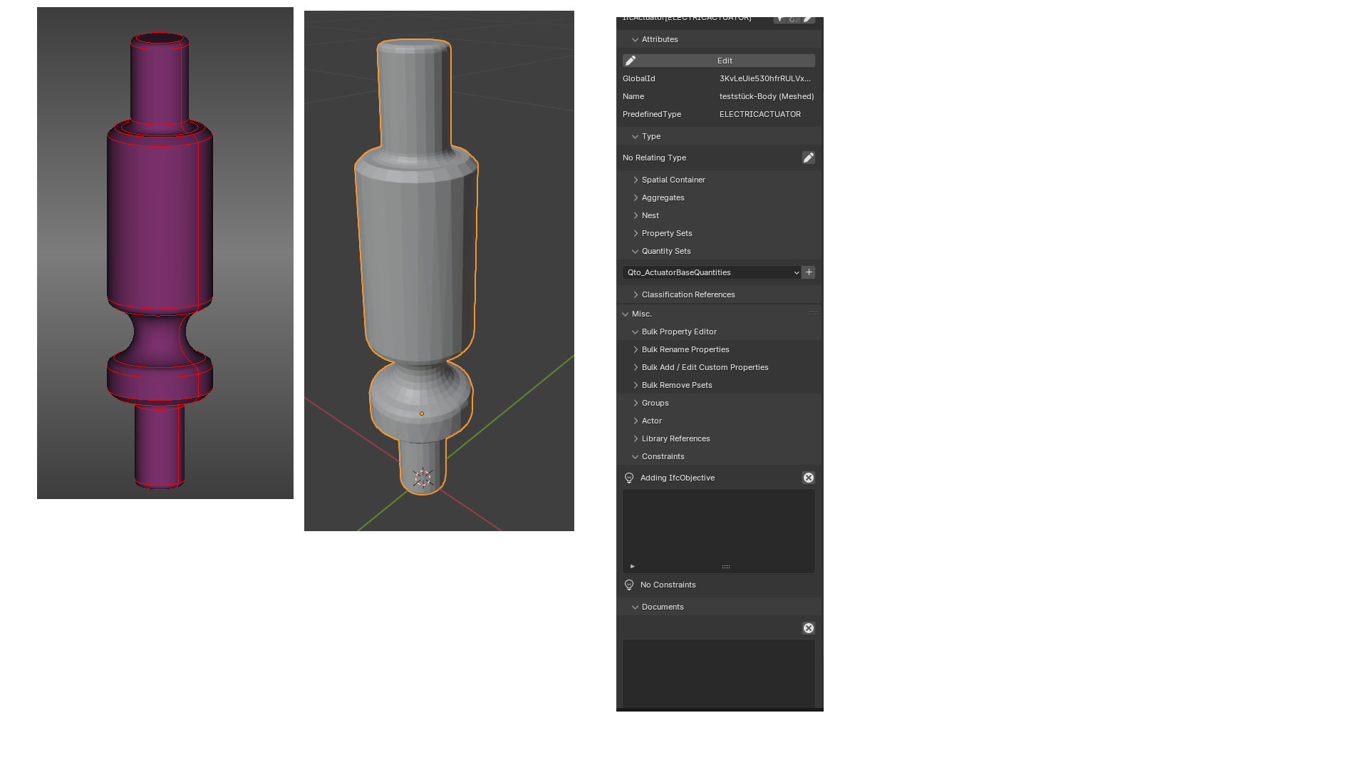
Imported in BB I couldn´t link to the file (as .step...) or attatch it at "object information - misc - documents" (that would be nice for documentation... but I´m just playing around)
This workflow imao is easier and faster than recreate the object in blender (it will also work for technical parts, that are downloaded from manufacturer where the other formats are not available, useable or manifold).
Maybe you can try export with BRep ? Then no tessellation is required.
"OIDA"