

🚧 FreeCAD Road Workbench

Hi everyone. I'm a Geomatics Engineer and interested with Transportation Engineering. I decide to create a FreeCAD workbench for my own needs.
GitHub: https://github.com/HakanSeven12/Road
Road is the Transportation and Geomatics Engineering workbench for FreeCAD.
✨ Features
- Geopoints ✔️
- Terrain ✔️
- Alignment ✔️
- Profile ✔️
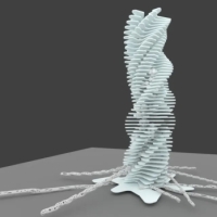
- Structure ✔️
- Superelevation ❌
- Road 🔄
- Regions ❌
- Sections ❌
- Volume ❌
- GeoLine ❌
- LandXML ❌
💬 Feedback and Support
💡 Need help? Join the discussion on the FreeCAD Forum: FreeCAD Road Workbench.
🐞 Found a bug? Report issues on GitHub.
📸 Screenshots
Tagged:


 and 7 others.
Comments
Amazing work—truly inspiring!
I'm looking to develop tools for Blender Bonsai to create and edit infrastructure models. I’ve been exploring your code and its development history, but since it's such a large and evolving project, I find some parts a bit challenging to understand.
For instance, in the terrain definition, is it possible to include break lines?
I feel like we could share a good amount of Python code and collaborate towards similar goals. What do you think? I haven’t written much yet, but I’d love to start working on something that could also benefit your project.
Thank you! I haven't worked on adding break lines yet, but I’d definitely like to include this feature for terrains in the future. I'm considering using the Triangle library for this. Have you explored any methods for handling break lines?
That sounds great! I’d like to collaborate
Good morning!
I'm currently studying how to implement a Constrained Delaunay Triangulation, but I'm still in an exploratory phase.
Aside from Triangle, I have come across some other interesting libraries that might be useful for our case:
1. MeshPy → Built on top of Triangle, MeshPy provides additional flexibility for mesh generation, making it useful for more advanced workflows.
2. CGAL (Computational Geometry Algorithms Library) → One of the most robust solutions, supporting CDT, adaptive meshing, and high-quality triangulation. It offers Python bindings (PyGAL), but it requires a more complex setup.
3. TetGen → While primarily designed for tetrahedral meshes, TetGen can also handle surface triangulations with constraints, which might be useful in some cases.
4. QGIS TIN Interpolation → Not a standalone library, but its TIN interpolation method supports break lines and point densification, and its source code could provide useful insights for implementing CDT.
I also noticed that your Terrain object seems to take inspiration from Civil 3D, which is quite interesting. However, I still find it a bit challenging to fully understand how it works. As soon as I find some time, I’d love to test and experiment with your code.
The code I wrote is actually quite simple. First, I reduce the points to 2D, then I perform triangulation using scipy.spatial.Delaunay. After that, I filter the output based on edge lengths and angles, and using the indices of 2D points, I generate a FreeCAD Mesh from the 3D points.
From there, other editing tools rely on the functions inside the Mesh object for further modifications.
@HakanSeven12 your approach looks great! Are you using Delaunay 2.5D? It seems like a solid choice, even though it comes with some limitations.
Today, I managed to use Triangle, but only to generate a free triangulation of a set of points in Blender.
Next step: Constraining triangles with discontinuity segments to achieve a more controlled result
Current workflow:
I'll continue experimenting with constraints and share updates soon! 🚀
Just in case (you probably already know), BlenderGIS has a 2.5D delaunay feature :)
Yes, I had seen the documentation, and while checking the wiki, I mistakenly thought that the triangulation done by BlenderGIS was limited to meshing between contour lines. However, after diving deeper into the BlenderGIS source code, I discovered that Blender already implements an algorithm that fits our needs: delaunay_2d_cdt().
It seems that with this, we can actually avoid using Triangle and perform the required constrained triangulations directly in Blender. I still need to study and fully understand how it works, though.
Thanks a lot for the tip! Next time, I need to learn to check what's already available in Blender before turning to third-party libraries 😅
Let me know if you decide to use triangle instead. It would be helpful for my progress
Considering the difficulties I had installing Triangle in the special Python distribution required for Blender, I’d say no. I don’t want users to struggle with complex setups just to use the application. Also, I find it a bit pointless not to fully leverage Blender’s built-in functionalities.
That said, you might also consider using Blender instead of Triangle, since it’s still Python. For now, I haven’t managed to get my process fully working, so I might still consider Triangle in the future, even if just to compare performance. https://github.com/domlysz/BlenderGIS/discussions/967
I’ll keep you updated on my progress. I’m working on the entire workflow, but I’m moving quite slowly. If you’re interested, you can check it out here: https://github.com/FraJoMen/GeometricRoadDesign. For now, I’m still stuck on clothoids! 😆🏃♂️
@FraJoMen , what’s the challenge with clothoid? Maybe I can give some pointers.
Thanks a lot for your availability! Right now, I'm studying and implementing the necessary formulas to compute and draw clothoid transitions. As a reference, I'm using this document (unfortunately, it's in Italian): http://www.madchild.it/ingciv/images/appunti/Strade/Esercitazione 2.pdf.
Basically, I still need to implement the series expansions to compute the clothoid points and develop the code to draw them in the global coordinate system. While working on these functions, I'm also considering the requirements of the Italian road design standards. For example, the clothoid parameter A must meet three different criteria. I was wondering—what formulas are typically used in the U.S. for road alignment verification?
That said, I don’t have a specific issue at the moment; I just need to find the time to implement these functions. For now, I'm keeping everything simple in Python https://github.com/FraJoMen/GeometricRoadDesign. Once the algorithms are ready and working, we could implement them in Blender to have full control over all steps and tools.
I saw you've worked a lot with clothoids, but I guess your focus was on the IFC side of things?
I wrote the geometric processing code for clothoid in IfcOpenShell. You could use IfcOpenShell instead of writing your own geometry processing. Attached is an example calculation for clothoid geometry using series expansion along with some reference information.
Hi Rick,
Thanks for your work on clothoid geometry in IfcOpenShell, and for sharing the reference material! It’s really appreciated.
I was wondering—have you also worked on flexure clothoids (transitions between consecutive curves in opposite directions) or continuity clothoids (transitions between consecutive curves in the same direction)?
Also, since I’m not very familiar with IfcOpenShell, could you share some practical examples of how clothoids are used ?
Thanks again!
Best,
Im interested too. Is there any reference code to create an alignment by using ifcopenshell?
I have not, but I imagine this could be decomposed to two similar problems of a single clothoid and circular arc.
Here is a reference that might be helpful. https://math.stackexchange.com/questions/1785816/calculating-coordinates-along-a-clothoid-betwen-2-curves
At this time, IfcOpenShell can only process the geometry of horizontal clothoids. If you define them in a model, IfcOpenShell can be used to compute a 4x4 placement matrix at any point along the clothoid. In the US, for highway and road works, clothoid is rarely used so I lack practical examples. Clothoids are occasionally encountered if working on an old section of roadway. Clothoids are used in rail applications but I don't have experience with that.
There is a discussion at https://wiki.osarch.org/index.php?title=IFC_-_Industry_Foundation_Classes/IFC_alignment along with some examples.
As far as authoring alignments in Bonsai, there aren't any features for this yet. I've been working on a feature to allow alignments to be defined by the PI method in a CSV and then import that into an IFC model in Bonsai. There is a pending pull request, https://github.com/IfcOpenShell/IfcOpenShell/pull/6234, that hopefully we can get all the loose ends cleaned up by the end of the week.
Attached is a jupyter notebook that illustrates how to compute the 4x4 matrix at a point along an IfcCompositeCurve.
Hi everyone,
After some time, I finally managed to dedicate attention to this project.
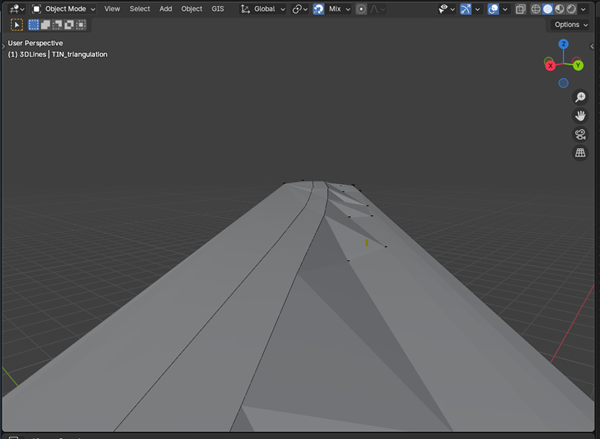
I've developed a simple script in Blender that allows the inclusion of linear constraints (breaklines) in the triangulation process, utilizing the capabilities of mathutils.geometry.delaunay_2d_cdt.
I wanted to share it here, as it might be useful to others. This utility actually enables the introduction of more complex constraints, such as outer boundaries and holes, although I haven't experimented with those yet.
I believe that fully leveraging delaunay_2d_cdt can yield excellent results in topographic modeling and the generation of 3D TINs directly within Blender.
I'll soon share a cleaner and more documented version of the script. In the meantime, if anyone is interested, I'm happy to exchange ideas or feedback!
Best regards,
FraJoMen
Awesome! Super fast!
My suggestions: