

IfcDistributionSystem | modeling a simple circuit

after noticing that the System UI got some improvement I wanted to give it a try and here is the result of a simple electrical system from distribution board to light:
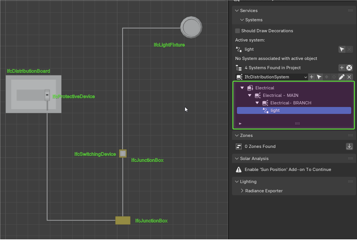
now I can happily select an IfcDistributionCircuit and visualize the entities assigned to it :)
OK it took me a little to fix ports and stuff but the result is quite nice
I am not a BIM electrical engineer, so if anybody wants to comment... more than welcome to do it!
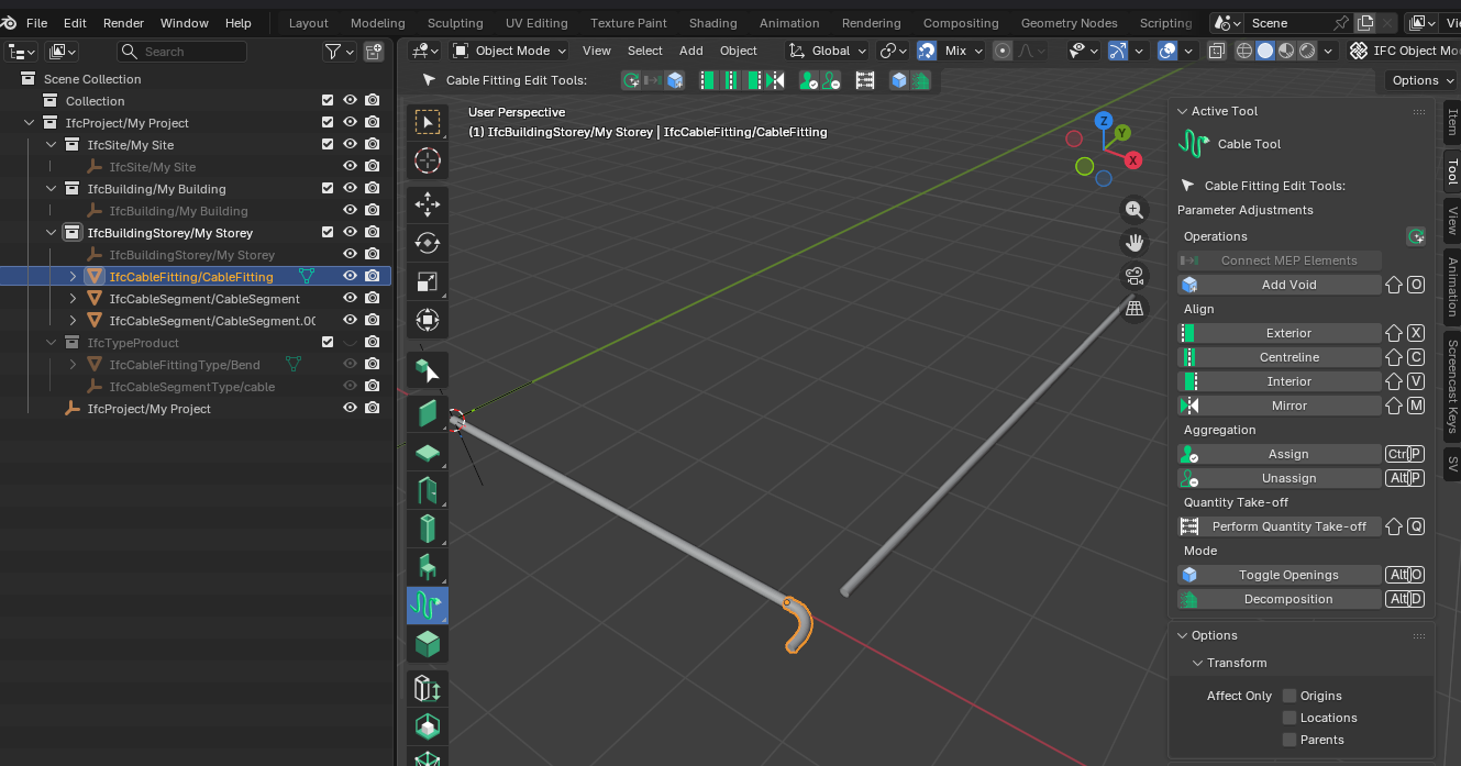
PS for the "cable" I used a curve > Data > Geometry (Shape on 2D) and converted it back to mesh before assigning the IfcCableSegment via "Tasselletion from Object" as Representation


 and 2 others.
Comments
Hi @steverugi,
I tried to reproduce this workflow with Blender 5 and today's BB update but was unsuccessful.
The Eyedropper doesn't select the mesh and creates an IfcCableSegment without geometry.
Can you confirm if this happens to you?
Another thing I noticed is that the quantities (of cables) are not calculated. I think a request for a new feature is warranted, what do you think?
Cheer's
@walpa
please make sure
1. the curve after shaping it is converted to a mesh and
2. assigned to IfcCableSegment and not IfcCableSegmentType (unless you want to repeat the same exact cable with bends and length over)
I think length cannot be calculated since the cable is not a geometry out of an extruded IFC profile but a mesh
Very strange here.
@walpa
I think you are missing the part from curve to solid as I indicated below (before turning it to mesh and IFC element)
That's true, you're right, my apologies.
Is there any way to insert an attribute or Pset that automatically identifies if an element is part of a IfcDistributionSystem?
@Falkeng, I believe that this option doesn't exist in the UI, but it would be a good idea for a new feature.
Similar to "Spatial Container" in the "Object Information" tab.
@Falkeng @walpa Is this somehow here?
@steverugi Do you know why Electrical - MAIN does not appear in the picture of groups? Is it supposed to appear?
Cheers!
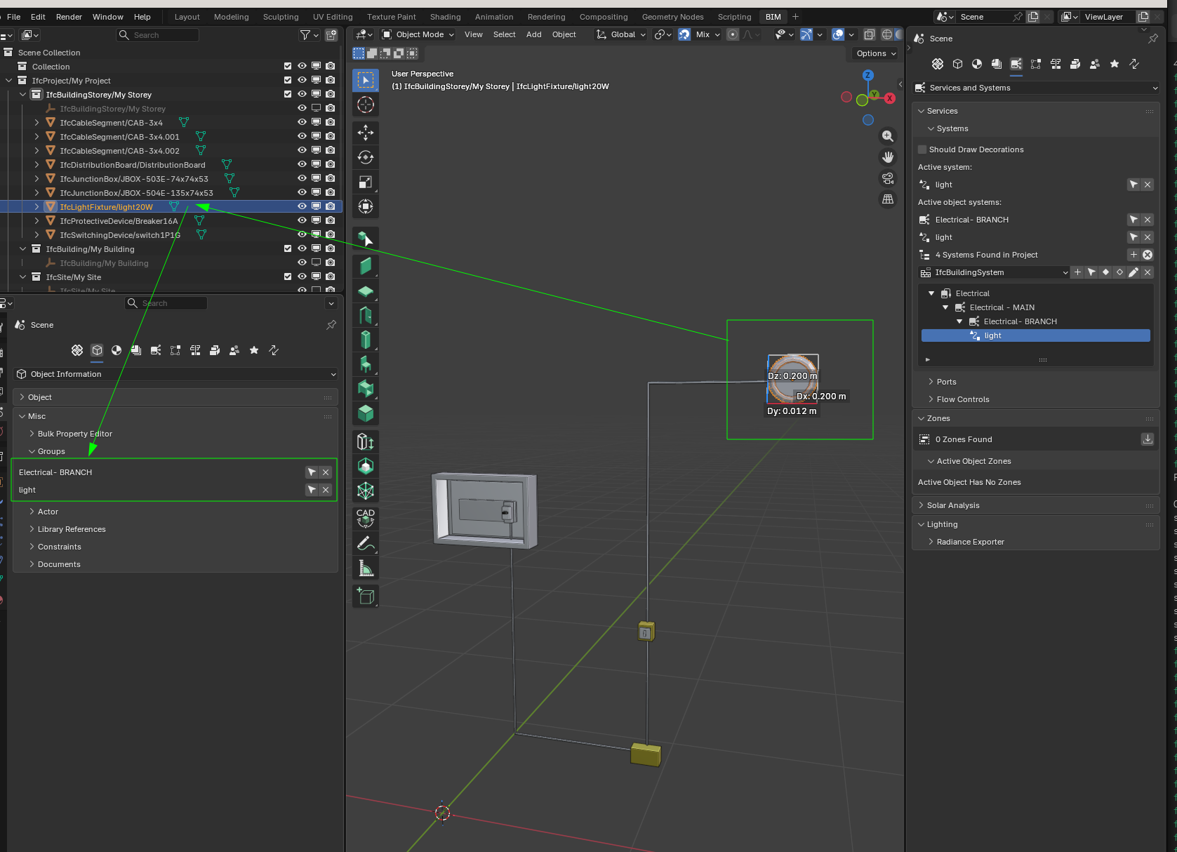
@Falkeng, I apologize, I forgot that IfcDistributionSystem inherits from IfcGroup and that it can be viewed in the groups UI.
Thanks @falken10vdl.
The hack for creating the cable mesh is interesting, but if you have to model many cables in many circuits, it would be laborious.
The cable tool allows you to create polylines, but when you confirm the creation, each edge is separated into several cable segments.
I think if there wasn't this segmentation, the tool would be more useful.
@bruno_perdigao and @falken10vdl, would that be possible?
I think that segmentation is good in the sense that it allows you to take quantities of the length to the different segments. I have created a simple PR connect the ports when creating several conected IfcFlowSegment with polyline #7611 to just get the ports connected. See it in action:
Cheers!
@falken10vdl
I played a bit with it and replaced solid cable with IfcCableSegmentType instances (useful to calculate lengths), now junciton boxes are not connected via port, only part of the system.
See revised system attached
Cheers
PS I noticed that when you use Object Information > Misc > Groups the arrow selects dependencies too
@falken10vdl, Yes, it already makes modeling much easier. I understand your point of view and I greatly appreciate your effort in this PR.
"Data venia", I feel I have to disagree somewhat with this solution.
If the cables could be modeled as a single element (ok, straight lines to facilitate quantity calculation would be acceptable), it would be a huge gain.
Would assigning IfcSweptDiskSolid using shape builder be an alternative?
Examples here and here.
Cheer's
@walpa You are right! Clearly for cables a single object for IfcFlowSegment with two ports makes more sense. That can already be done, as @steverugi has been showing. You create the geometry convert to IFC (Shft-A Add Ifc Element) and add the two ports.
Other possibility is just use polyline with one segment :) from start to finish but I guess that is an overkill simplification.
In the case of polyline as a better approximation you would like to just generate the geometry but assign all to a single IfcFlowSegment with ports in the first and last points drawn? (so afterwards if you want to change the geometry you will need to tab into it, right?)
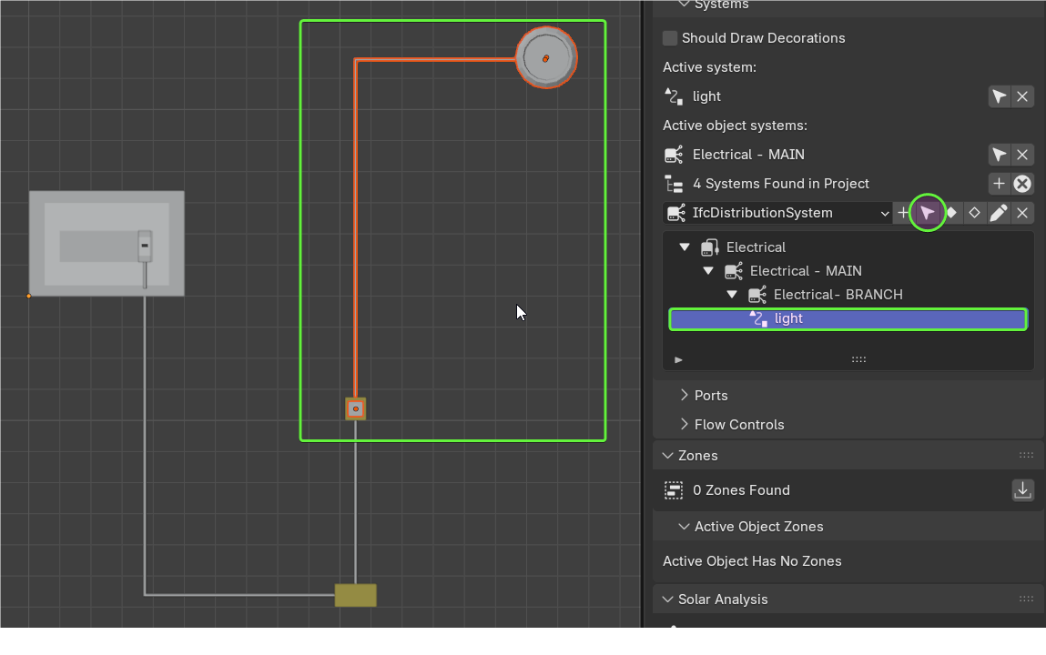
I have meanwhile updated the PR to add an operator properly change the ports sink/source... so you can create a path by just setting the status of one connected port and it will traverse the follwoing connected ports (as long as there are two per element) setting up corectly the ports:
Cheers!
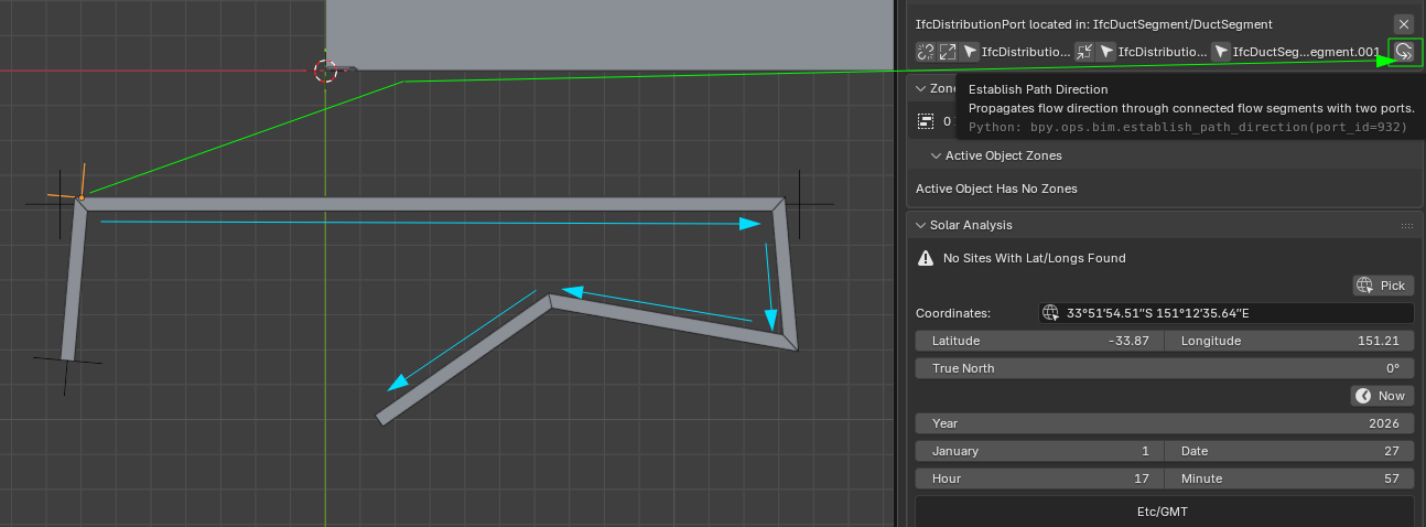
Here in action the "Establish Path Direction"
@walpa I guess this is useful more for ventilation systems.
Cheers!
Wow!!! I'd been thinking about this feature for a long time, but I never imagined it would be feasible or that it would arrive so soon. :)
Yes, for cables I believe it would be a more user-friendly workflow.
The ability to edit the path with tab would be wonderful.
@falken10vdl
currently
what if
is it difficult? thanks again for the phenomenal efforts made for all of us, seriously, set up a buy me a coffee account!
cheers
I would like to add another perspective to this discussion regarding cable modeling:
1. Cables in Conduits/Carriers: When modeling cables within a conduit or cable carrier, two pieces of information are critical: the path (to accurately measure total cable length) and the fill ratio (to ensure compliance with technical standards).
2. Exposed/Free Routing: If the cable is not housed in a carrier, its physical geometry becomes more important. We need precise modeling to perform clash detection (evading collisions) and to measure the exact routing length.
3. Connectivity: We should also consider cable connections. It would be beneficial to identify and quantify the termination points and connector types within the model
The current implementation remains, even for complex paths? That is, for each curve or small change of direction, would it be a separate segment with its respective ports?
Are both options possible?
Cheers
Yes, but I wouldn't see bends used in this process as I would for conduits.
Changes of direction are already available (if ai understand you correctly) in the current UI
Right?
;)
2. This can be done but I think it is not evident in blender. That was my first idea, let the user decide in a sequence of IfcFlowSegments with two ports each (or two ports each except the first and/or last that could have just one) and just connect them. Unfortunately I think that when you select several objects in blender in the 3dview you just get access to active & selected, but selected is not an ordered list so you cannot assume it is created in the order the user selected the objects. It looks that there are ways to workarround this like https://blender.stackexchange.com/questions/253427/python-blender-get-selected-object-in-order-of-selection Let me open another topic regarding this issue because to me keeping the order seems to be a valuable info probably in many other circumstances in bonsai
The "Establish Path Direction" does the following:
1. You select a port which must be connected to anothre element. Lest call this Port1
2. In the "Port" panel you press "Establish Path Direction"
3. It will do the following. Look if the element to which the port is connected is IfcFlowElement and has 2 ports (Lets call them Port2 & Port3 withi Port1-2 connected). If that is the case It will start, based on the type of the Port1 (lets say it is sink) modifying the value of Port2 & Port3 as per sink-source-sink... rule It will then cheech if Port3 is connected to anothere element. If true... loop
So as you can see, as long a you have a run of IfcFlowElements connected with two ports each you are able to re "align" the flow. So if you add /delete elements, as long as they are connected in a run, then you can again use the "Establish Path Direction" operator.
Cheers!
Yes, if you use bend it will create an IfcCableFitting event, which is not consistent.
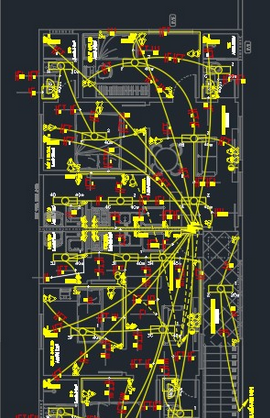
Yes, the current UI allows changing direction, but now imagine modeling something like that with many sections of straight lines for each cable, for each circuit... :)
Cheers!
@Moult I have seen you have contributed to IfcOutlet :)
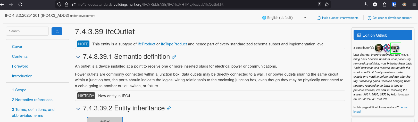
In the comments below from @Falkeng what is your view around cabling in a project vs IFC modeling? I mean from what I understand but I might not be right :) (see the picture of my previous comment) IFC only models energy "flow" not actual wiring? Namely return/ground cabling is out of the equation?
Thanks!
@falken10vdl
my understanding is that IfcCableSegment can be used for any role so long as you respect routing constraints in IfcDistributionPort
I would personally (my knowledge on the subject is limited) only model single lines that can have multiple cores and add details in the relevant Pset.
For quantity purposes is more than adequate as is, apart from the segment/port connections that could use some improvement if and when possible.
Thanks
ping @lukas :)
In my dreams, as a user, I would like to have an interface that makes all the work easier for me:
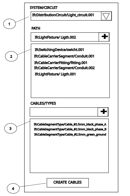
Create the path using the location points of the ports of each item in the order in (2) and for each type in (3) create a cable segment and then assign the created cables to circuit in (1).
The cable modeled with a polyline that could be edited later to:
1 - reposition the cable
2 - increase or decrease the cable size
3 - improve the geometry with fillets, curves or chamfers
4 - separate the cable into 2 segments to create branches (using the appropriate IfcCableFittingType with ports)
Cheers
I am following this perfect new thread, but from some distance, give time to read it in detail.
Then I can try to give you some advice what the german constraints are.. at least what is necessary for a BOM (bill of materials ?).
One need the total length of each cable(Type,Mounting).
Type(Number of wire, Diameter of each wire, Material of the wire, Protection type of the cable)
Mounting( conduit(typ) or in/on wall(type)), fireproof class, acoustic class)
As for the exact length for each cable, one can have a 10% margin.. since whatever you plan and ask for an offer, the contractor will always major your quantities by 10% or more (or the price for it).
But one can set radius constraints to each cable depending on its size, this can prevent impossible configurations.
Each cable is assigned to a Circuitbreaker.
Once such IFC-graph for the electrical distribution is set, one should try to connect to Qelectrotech or Kicad for Schematas and Simulations.
You are all genius..
Bravo.
@lukas when you say cable do you mean each individual wire? You know that in Europe, at least, many times the "neutral" wire and the "live" wire do not go together all the time. Many switchboxes just have the "live" wire ans then there is another neutral wire comming from the lights back to the electric distribution box. Do you model the neutral wire for quantity take off but without directionality? What about the ground wire?
Thanks!