

Complex CurtainWall designed with FreeCAD
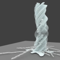
FreeCAD arch case: Complex CurtainWall designed by FreeCAD user sanderboer.
Forum thread https://forum.freecadweb.org/viewtopic.php?f=23&t=39218
Link includes images, discussion and link to FreeCAD file and FreeCAD macro
Tagged:


Comments
The user @sanderboer wrote a Macro to generate this complex form.
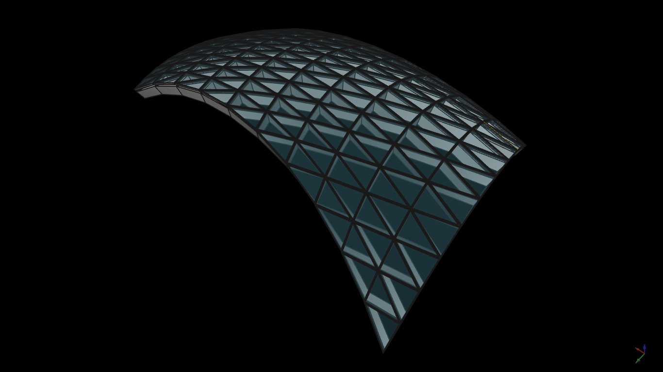
A close-up posted by the author :D
@paullee Thanks for cross posting this. I wonder how easy it is to make this part of the curtain wall tool? Also, the original author mentioned that at the moment it planarises tris - amazing! But I wonder if there are other ways of populating a curtain wall....
I probably need to experiment with it myself a little, I remember having the conversations with you and yorik a few years back on this exact same topic, but my python skills in freecad a bit rusty (not that they were ever that good)...
@bitacovir is always so kind to cross-post FreeCAD models and discussion here particularly in a wiki about AEC modelling in fact :D
Do you mean if it is possible to turn @sanderboer 's Macro into a FreeCAD Arch/BIM Objects? It should be quite easy in fact. I have a look at the Macro and find it is so clean and neat, easy to understand. It probably works on any Surface (Face) :D See the 'simple instruction' I just add in the original thread in FC forum
And recently trying to understand @yorik 's Curtain Wall's feature (and yet to read / watch the video in the thread 'Technical inspiration from elsewhere')
One thing to improve, on both 'tools' is to support panels with different size / staggered grid etc. Currently @yorik Curtain Wall assume equal distance divisions or otherwise need the ArchGrid to work as Base. ArchGrid is not very handy for large surface like a multi-storey building... maybe just model a typical pattern and repeat that?
Maybe you can set out based on your experience what features/ desirable workflow / flexibilities a Curtain Wall tools should be (particularly from a viewpoint of an Architect rather than programmer), and hopefully @yorik and/or other peoples can improve all the current tools ? :D Likewise, what are desirable workflow for the 'Procedural Pavilion' :D
@paullee , the current curtain wall implementation is a good start. It's the beginning of the complex puzzle that is curtain walls, whereas the macro is a good start from a different stand point.
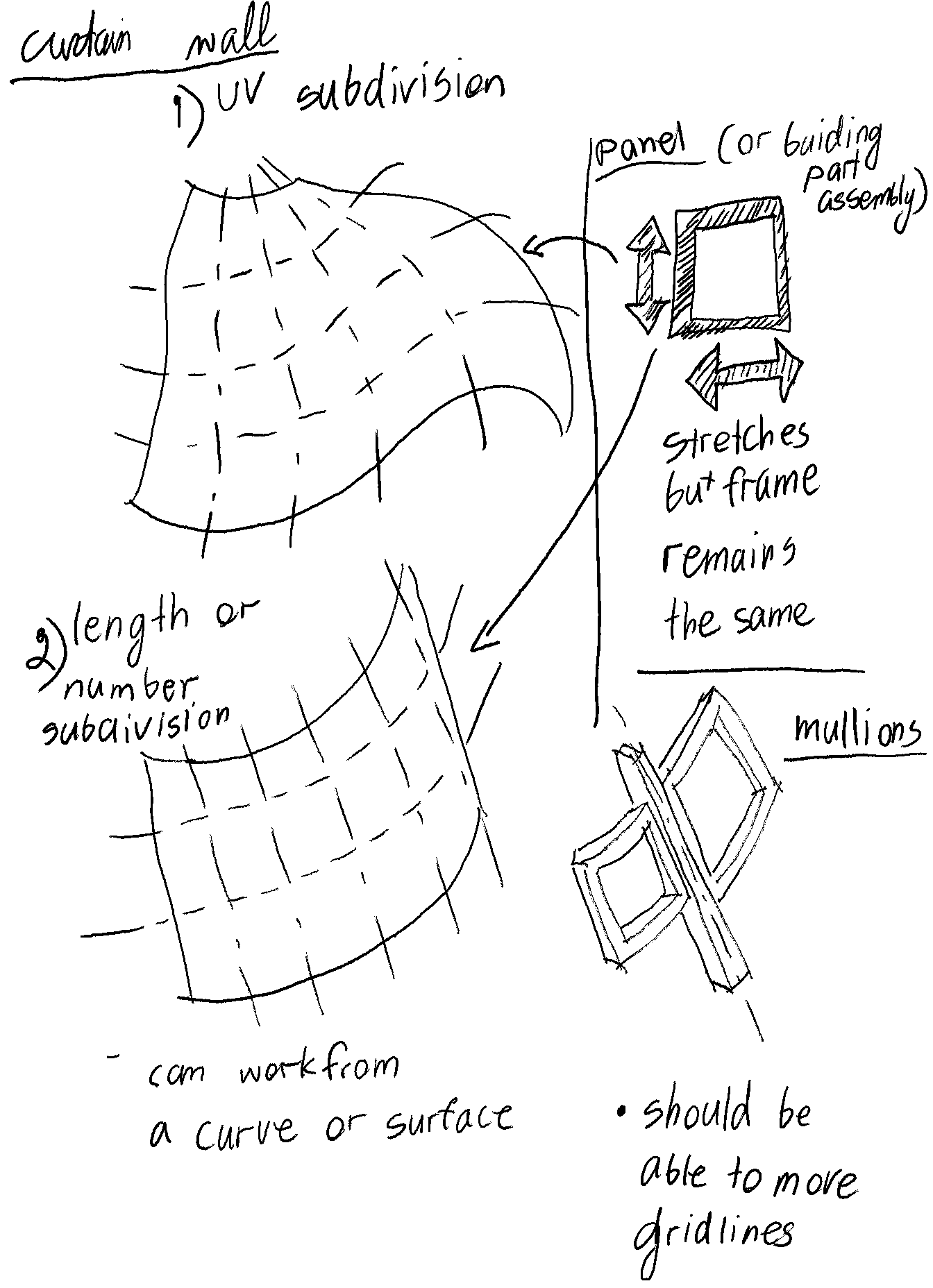
In my experience, there are usually two ways to approach a curtain wall - 1) UV subdivision and 2)by distance/number of divisions. Both ideally work with panels and mullions. The panels themselves can be an assembly that contains subpanels. The simplest panels are fixed glazing, to more complex bottom solid element, operable window, and top element all as a panel. Here is a little sketch showing the ideas
From design perspective, flexibility in both fixed divisions by UV, number, or distance is necessary.
Then, customising the grid is sometimes necessary as well. The custom grid doesn't need to be part of the same object as the equally subdivided grid, but in many cases, accommodating for walls, columns, corner conditions and balconies require custom distances.
The panel or buildingPart could be as simple as a fixed window or as complex as balcony/block wall/sliding doors assembly. In some cases, a panel of the grid may need to be swapped for a different type within the same grid layout for e.g. louvres, doors, etc. The model for which you helped with the arrays could be done with a curtain wall/grid tool as an example.
From BIM perspective, all the same and different elements would need to be scheduled - mullions, panels, subpanels, panel types, number of panels of each type, number of mullions of each type, etc.
While thinking what to do, make a simple interactive Gui button for the @sander Macro :D
@sander 's Macro always triangulate the surface with UV subdivision.
Wondering what is the algorithm if quadrilateral / rectangular faces is required, any idea?
Thanks.
@paulee planar quadrilateral glazing is much easier to build, like an order of magnitude easier. Triangles are a last resort if you can't do it any other way. But for quad faces you need to take care when designing the shell as not all shells can be decomposed into quads. I wrote a paper on this: Methods for Creating Curved Shell Structures From Sheet Materials, it is mostly about thin-shell rolled-plate structures, but the principles are the same.
Wow! The paper is highly technical, wonder if I can understand some part of it :D
@sander 's Macro seems works on any arbitrary surface. It check the UV, subdivide by a certain numbers and find the coordinate. It is not certain if the 4 coordinates lie on same planer so it simply triangulate it. So it seems to me, triangle is easier in this sense?
Thanks!
EDIT - it seems the section 1 of the paper spell out the aim to generate develop-able surfaces from complex curved shapes... :D
OK, having attempted to read it through a numbers of time, I can hardly understand the 'mathematics' / 'geometrical construct' start from Method Two... :Oops
(Yet to learn what are spline / bezier curve / b-spline ...? )
So many questions, thanks :D
@paullee Thanks I did try to use as many difficult words as possible :)
The point of the paper is that the majority of NURBS surfaces are effectively unbuildable, you have to decompose them to triangles, or do some horribly expensive CNC or 3D printing. However there are these other classes of curved shapes that are very buildable, they can be decomposed into planar quads or developable plate.
I did this originally in AutoCAD using
RULESURFbetween 3D splines, but have since been using Sverchok for the method one shapes and the homography transform. I'm sure they are trivially implementable in FreeCAD, but as Mr X says, So much to do, so little time.I've never heard of a Gordon Surface until now, yes "spline" just means any 3D curved line, they could just as easily be simple arcs.
I try to do what I understand in 'Method 1', in FreeCAD :-
Now, it is fun :D
(FreeCAD file *.FCStd renamed to *.zip for file upload here, rename back the extension to use)
YouTube Video
 https://youtu.be/s0U91VyoigI
@paullee cool, hope it is working as expected. The rectangular panel curtain wall looks good
Thanks, hope could understand the rest and test later :D
Made the third scaled bezier by Clone as described in the paper, all quadrilateral panels :D
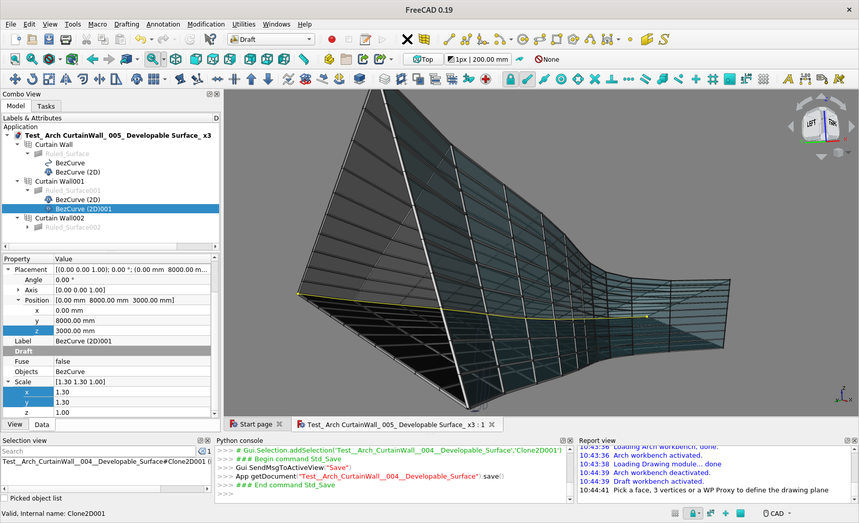
Trying to understand 'Method 2' - not sure if this is correct interpretation ?
https://youtu.be/RFGQXKiokgU
@paullee looks good to me, if you have planar quads then you are doing something right
@paullee these look impressive! now what would be the way to schedule the components?
Hmmm, I remember you had raised similar issues earlier.
I have a glance at the Arch_CurtainWall wiki. Seems pretty basic at the moment, horizontal mullion numbers, vertical mullion numbers, panels numbers. Surface Area would be easy to return.
Maybe you can leave a feature request with desirable components schedule to be return in the FC Arch/BIM Forum and Mantis BugTracker? :)
Still figuring out how to do curved surfaces in other Methods illustrated in @brunopostle's paper.
Any gap to try those? :D
Whilst still thinking how to do something like tissue, testing what current FreeCAD can do.
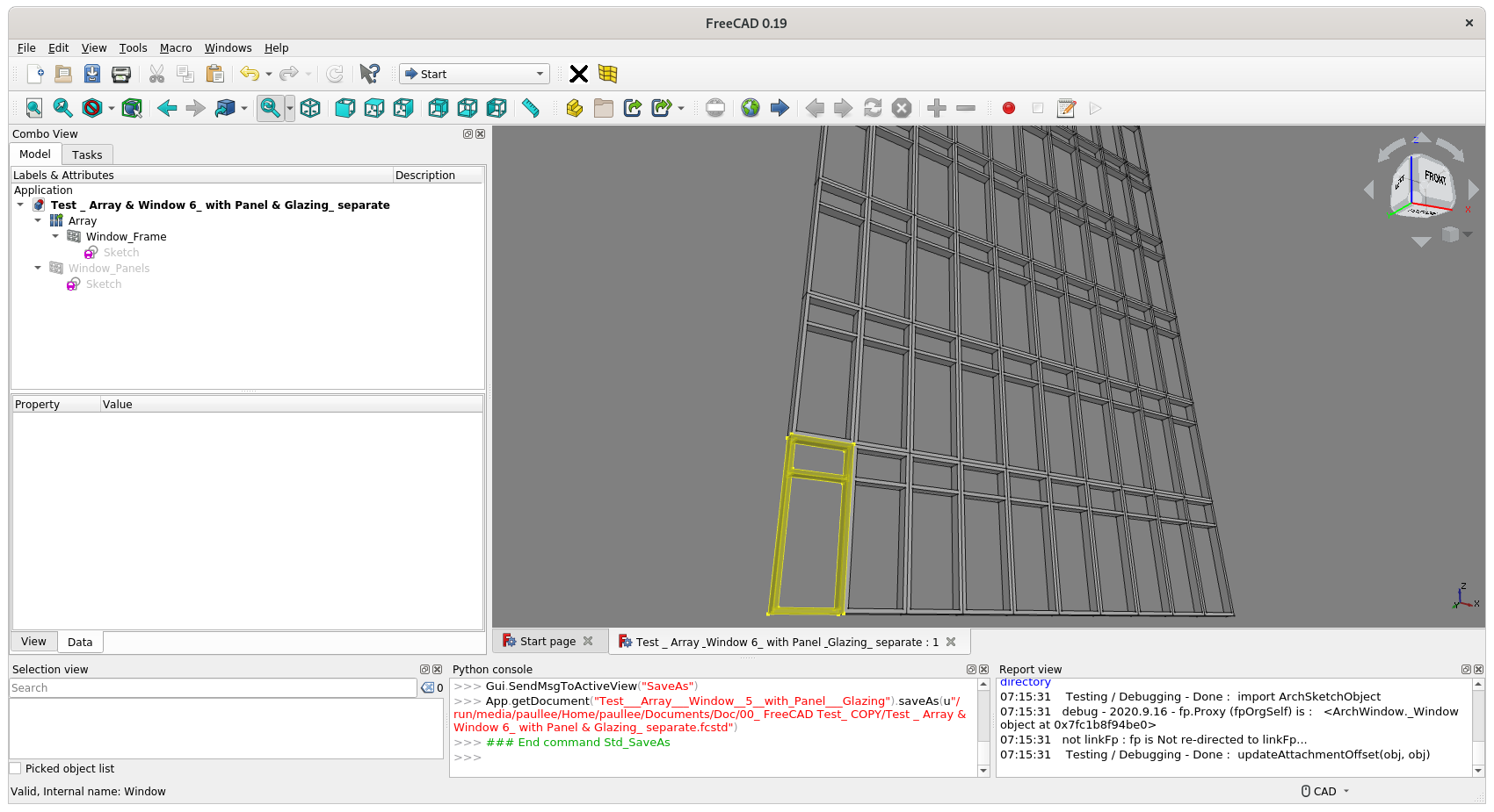
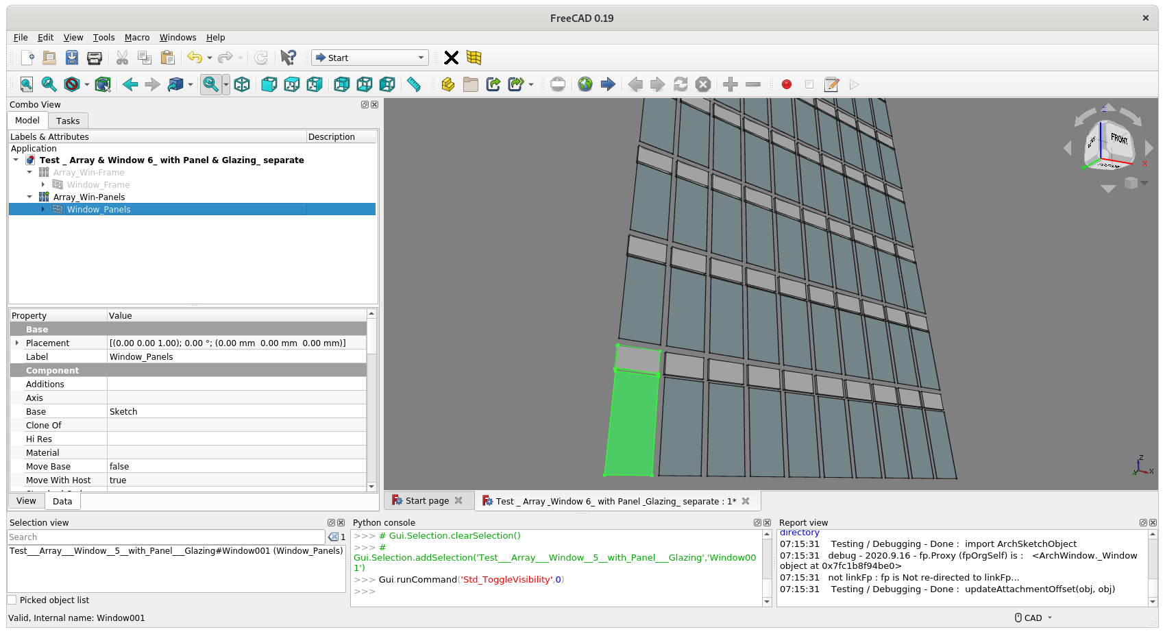
Cross-posting Window, CurtainWall & LinkArray
Nice, is thee a way to have the mullions and panels as separate objects?
Yes, the Window object is very flexible, e.g. you can make 2 Window objects both based on same underlying Sketch, then 1 Window show the Frame, and the other on the panels. Or even separate objects for solid panel and glazed panel.
Then, it is a simple array of the above 'parts' :)
This way has better breakdown of quantities also.
In fact, it is just a matter of a few clicks when the above model is made :D
It's done.
(rename the attach model *.zip to *.FCStd to open in FreeCAD)
Hi @brunopostle ! Trying again to have a closer look at Method 2 and Method 4 again.
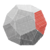
One thing not understood and trying to make sense of the diagrams quoted below - are those 'homothetic lines / triangular surfaces' must be parallel to each other ? Not sure in the perspective diagrams :D
Thanks again !
@paullee yes, the red lines/triangles are scaled copies of each other (with translation but no rotation)
Stuck :) Just have some fun with this model :D
In theory, all the spectular stuff as shown in this thread should be possible in native IFC? ?
To my understanding, all are co-planar panels so possible ?
Anybody can try ? :D
IFC doesn't have a 'thickened shell' representation. Extruded objects have to be planar.