@yorik that would be fantastic! I am available to provide any support necessary towards this direction.
In the analysis-models repository of IfcOpenShell there are a few models you can see.
This example (portal_01) is actually the ONLY one provided by buildingSmart (original link here).
cantilever_01 was created by @Moult in BlenderBIM while beam_01, building_01 and building_02 have been extracted from ETABS, a commercial structural software. The last two that contain also walls and slabs have various problems as there are no connections between surface elements. I would suggest you to see portal_01 but also cantilever_01, which I think is created more to the state-of-the-art, especially regarding representation contexts and material properties.
Great! @Moult 's example is super interesting because it combines both "physical" model and analysis representation. I'll try to do that as well in FreeCAD. To resume what I found out:
There are two (or more) IfcGeometricRepresentationContext: one for normal geometry (body) and one for wireframe structural analysis. But that is apparently just for model cleanliness, to separate all the representations of one type from another.
There is an IfcStructuralAnalysisModel entity which relates to the IfcProject (weird way to define that this is an analytic model If you ask me... what about all the fuss with MVDs)
You cannot apparently have an IfcBeam with structural analysis properties. So if you want to have structural analysis, you MUST use IfcStructuralItem-derived object (IfcStructuralCurveMember, IfcStructuralPointConnection, etc)
Representations of structural items are made of IfcTopologyRepresentation, which are made of edges (for members) or vertices (for point connections).
The member product has one representation (the edge), and connects to point connections via IfcRelConnectStructuralMember
The member can have another representation (a 3-dimensinal body). I don't see however how an application can distinguish between the different representations, which one is to be used for structural analysis, other than figuring out by the name ("body" or "edge", for ex),or by the representation context it is associated with (but there too there only differ by name, so it is pretty weak
I think you got it pretty right. Here are some minor comments and I hope Dion can chip in later with more comments
There are two (or more) IfcGeometricRepresentationContext
To be more exact they are SubContexts, although in the other files other than cantilever_01 SubContexts are not used.
Furthermore, I think the context for structural elements is 'Reference' which is used in both cantilever_01 and portal_01, although the latter does not define it in the beginning like in the former.
By the way, the structural entity is completely independent from from linear representation in the IfcBeam / IfcColumn etc. In fact, you can have a structural beam in IFC without even having an IfcBeam ... weird, I know! You can still derive one from the other, but just a heads up :)
Okay we now have something up and running in FreeCAD!
Commit: https://github.com/FreeCAD/FreeCAD/commit/6271887cc656d8571000de2f4e06df2be8d84105
Basically, with this commit, under Edit->Preferences->Import/Export->IFC export, we can now set the export model to either standard (IfcProducts), analytic model, or hybrid (both). After that, it's just a matter of exporting a model to IFC normally.
What happens:
All Arch Structure objects have their node lines exported as IfcStructuralMember
All objects that have no solids or faces (wireframes) are also exported as IfcStructuralMember (not sure if that is really useful, still testing)
All coincident points in the above objects are exported as IfcStructuralConnectionPoint
If hybrid mode, an IfcRelAssignsToProduct relates the IfcStructuralMember and the corresponding IfcProduct
Here is a test file if anyone is interested in testing:
@yorik I tested your example with ifc2ca and I have the following comments:
1) In IFCSTRUCTURALCURVEMEMBER the last input is the Z axis of the element local axes. You have provided for all these elements: #7=IFCDIRECTION((0.,0.,1.)); but this direction should be specific for each curve member and certainly not parallel to the axis defined between the two points of the curve. From its definition
The local coordinate system is established by the reference curve given by topology representation and by the attribute Axis. The local x axis is parallel with the tangent on the reference curve. The local z axis is located in the surface which is created by sweeping Axis along the reference curve and is directed according to Axis. The local y axis is directed such that x,y,z form a right-handed Cartesian coordinate system.
Thus in this example the local axes for the vertical elements cannot be defined. As a rule of thumb I would say for horizontal curves it can be a vertical direction and for vertical curves (columns) can be along X or along Y global axis (preferable the latter in my opinion so that for a rectangle profile xDim and yDim are aligned with X and Y global axes
2) In #24=IFCGEOMETRICREPRESENTATIONSUBCONTEXT('Analysis','Axis',*,*,*,*,#21,$,.GRAPH_VIEW.,$); I would expect to see 'Referenceinstead ofAnalysisandModelinstead ofAxis` but I am not 100% sure what you have provided is not ok. In any case I am modifying the ifc2ca script to read any subcontext that has an 'Edge' type as representation for a structural curve.
3) I am also modifying the script to read the curve members even if there is no IFCRELASSOCIATESMATERIAL
With all these considerations I can parse the file you provided and create the geometry and mesh.
Amazing!! Thanks a lot for testing @Jesusbill . I'll fix the Z axis already. For the name of the context, since this name is apparently arbitrary, I thought of using something more meaningful than "Reference", but it makes no difference to change...
I'll also add support for slabs, @bernd suggested using IfcStructuralSurfaceMember
The Reference context name I think is a buildingSMART thing - they use it in their structural examples for how to store topology. I agree it seems a bit strange to me too :)
Update on the Ifc2CA project: All types of point connections between structural curve members (beams/columns/etc) have now been implemented. This includes:
internal releases AND/OR internal springs for each DOF;
RIGID links in series with internal springs;
external springs for point supports.
An additional example has been added of a typical grid of primary and secondary beams, with a strict center-line modelling technique and rigid links to account for the correct length and position of the structural elements. Various cases for the beam-to-beam connections are investigated with rigid, pinned, or flexible, with user-defined stiffness, conditions.
Hi all. This is looking great and exciting. So I'm thinking about the best way to document it. I've created some things on the wiki https://wiki.osarch.org/index.php?title=Code_Aster https://wiki.osarch.org/index.php?title=Category:Code_Aster
I think it would be great if some of the work in this thread could be done based on IFC from the FreeCAD model of the "Open Source House" https://wiki.osarch.org/index.php?title=AECO_Workflow_Examples
I've got a not very secret plan to see if we can focus lots of processes on one project so we can document how we get closer to a full workflow. on a real project. There are parts of that project @bernd has worked on and have a geometry which I think is suitable. Maybe @yorik could use that file to add the necessary data. There is already some FEM done inside FreeCAD but documenting an IFC based workflow should also be done in parallel.
Anyway, I've planted the suggestion.
@duncan the wiki pages you created for Code_Aster look great!
I will start looking into the Open Source House with the intention of creating a model with what is now available in IFC to Code_Aster; mostly line elements like beams and columns and their connections. Loads may be added "manually" directly in the input files if they will not be implemented by that time in the automated procedure, but I guess the workflow shown can evolve together with the development.
Hi Ioannis @Jesusbill,
As far as I know, the workflow you implement could be something like this: IFC --> Code_Aster --> ParaView (as viewer)
So, as we both know ParaView is based on VTK which is an old technology, so why not view/represent results on Blender? Which is based on OpenGL and other efficient technologies
The workflow would be: IFC --> Code_Aster --> Blender
Hi @ReD_CoDE I don't see that much the issue of visualizing the results from Code_Aster as much as setting up the analysis and obtaining the results from Code_Aster. Paraview, which I think is the top open-source visualization library for scientific computing, is used in my examples as it can read directly the ".med" files produced by Code_Aster (to be precise it is a modified version of ParaView that has this capability of reading these files, which is called ParaVis and is a module in Salome-Meca). Of course, one can parse the results and visualize them in whatever tool he wants. Blender could be one of these (as far as I know you can also visualize paraview results directly in Blender, I have seen such examples from CFD analyses) but to do that from zero one would need to create a visualization module which would have the possibility to view diagrams, contours with a colormap, the deformed shape from a given analysis case, animations for time-series of results and so on. Parsing the results from a med file could be done with the MEDCoupling library, the meshio library, which handles a lot of the mainstream file types for scientific computing, or other libraries I am not aware of. For web visualization one could use for example the parsed data and threejs to create a scene with the results, as this example from the official threejs repo (https://threejs.org/examples/webgl_geometry_colors_lookuptable.html). The possibilities are infinite once you have run the analyses and obtained the med file.
I would be also interested in a workflow of: IFC --> Code_Aster --> IFC but I am afraid that the current IFC schema for structural analysis does not cover this area; there is the possibility to write back the metadata of an analysis and some partial results (point forces and displacements) but not the whole results for each 1D and 2D element, which I think is a major drawback. But at the moment I have not investigated thoroughly these options, I am currently on the part of implementing correctly the connections and supports for bi-dimensional elements like walls, slabs, etc.
@duncan during the last meetup you expressed your availability to help with the creation of some structural ifc models using commercial software. As I had said I have not managed to get any models that contain connections between planar elements like walls and slabs. I have tried with ETABS and Sofistik and I was wondering if you can have access to Robot Structural. If this is the case and you have the time we could start with a simple model (a wall with a support at the base) and see what we get.
Thanks @bernd! If you can get something out of AxisVM would be great. I have seen your examples but I would prefer to work on IFC4 versions, as there are some changes and I would prefer tackle with IFC2x3 later. So, it would make sense only if AxisVM supports IFC4.
I have already tried with ETABs and Sofistik and my problem is with curve connections and supports regarding planar elements, such as slabs and walls. These connections are not exported in the structural ifc files and that's where I am stuck at the moment. If you can try with AxisVM even with a very simple model of two walls connected with support at the base or a model similar to the one in your description folder, that would be great.
In any case, this week I plan to work quite a bit on this so I could possibly look also into your existing models or try to extract sth with BlenderBIM.
@Jesusbill I've just checked and even though I do have access to Robot there is am 11 euro daily charge my manager might not be too happy about. So for Robot I can't help. Do you want me to ask around to hear if anyone has it installed and uses it? I could maybe ask them for something basic. You say 'a wall with a support at the base' but that doesn't sound very specific to me. Let me know if we should pursue this. I notice a Tekla Structures 2018 licensed is available. There are also a bunch of Strusoft tools.
@Duncan thanks, I have managed to make a few steps forward these days so at this moment it is not indispensable. That said, if you can ask and there is any engineer that uses it, it could be useful to have an export in structural ifc. Any model that contains also slabs, or walls and either connections between them (connection along a line) or a support at the base (always along a line) (support means simply that the displacement and rotation there is blocked) it would be good. The issue is that no software tested until now handles this type of connections, they do handle connections between beams and columns and with slabs and walls (point connections) but not line connections.
But as I said, it would be good to have but not absolutely necessary, I am going forward with my interpretation and I guess in the future we can modify anything that does not look consistent based on valid export models.
Regarding Strusoft I am not aware but at this point my bet is that it will not handle this issue as well, given that the big players do not as well.
@Jesusbill said: @duncan during the last meetup you expressed your availability to help with the creation of some structural ifc models using commercial software.
I have access to Graitec Advance Design which exports IFC, but it doen't appear to transfer any connection or anchor information. Attached a test with two steel members, I didn't think to try slabs or walls. It actually has lots of IFC options for different target software, but I'll need to find some time to go through them all.
Thank you @brunopostle for your effort, luckily I have found the way to go on without any reference files from other software. Not sure if Graitec Advanced Design can handle ifc with structural analysis entities. The file you sent does not contain any IfcStructural* objects.
Support for connections between slabs, walls, etc. has now been added in ifc-to-code_aster and two examples added in the analysis-models.
The examples are created based on a script that does the inverse operation of the original script, taking as input a json file and returning the structural ifc file.
@Jesusbill said:
Thank you @brunopostle for your effort, luckily I have found the way to go on without any reference files from other software. Not sure if Graitec Advanced Design can handle ifc with structural analysis entities. The file you sent does not contain any IfcStructural* objects.
The IFC files from Advance Design did look incomplete.
Is your workflow something like this:
author IFC file (including connection information) in blenderbim
use ifc2ca to generate all the input files for analysis, or does the loading regime need to be authored separately?
run analysis
I see that @moult is working on an ifcsverchok blender add-on. I'm looking forward to the day when I can generate a structure in Sverchok with all the relevant IfcStructural elements ready for analysis.
@brunopostle yes that is plausible workflow. Loads can definitely be in the IFC file as well, except for seismic which are not considered, but other than that typical static loads, loadcases and loadcase combinations I believe are considered. Loads are next in line regarding my work after implementing also surface connections and refining the algorithms for all connections in general as at the moment there are some limitations in what I did for curve connections and I am trying to overcome those for a better and straight-forward usability.
IfcSverchok looks promising but a structural engineer/developer has to step in to implement ifc structural, Dion cannot do everything, and the same would be needed for BlenderBIM also as at the moment there has not been much progress at the UI level for structural analysis concepts. I would be willing to work on this but I wish I could have also at least another person that helps, my experience in blender is minimal and I do not want to undertake too much and not deliver, given also the work needed for ifc2ca. Let's see how things evolve :)
hello everyone. First off, I am fairly new to OSArch and find all of the projects from BlenderBIM to integration with code_aster, etc. quite simply amazing to the opportunities it presents. As a structural engineer (who knows rudimentary Python programming), I'm quite interested in finding a suitable workflow for perparing input files from IFC for structural analysis. @Jesusbill I'm not so familiar with IFC nevermind ifc structural but in my spare time I'm going to start learning what I can on how to use BlenderBIM to author ifc files and I'm sure at some point I'd be able to help out with providing feedback/ideas on structural analysis concepts at a UI level. Not sure how much time I will be able to spend on this at the moment. Also i am thinking that a "IFC to code_aster to IFC" workflow would be amazing but tend to think that rather than writing the whole results for each 1D or 2D element it would seem better to me to also evaluate the analysis results in terms of the plausibility of the geometric parameters within the structural analysis round-tripping "IFC to code_aster to IFC" workflow. As documenting the results of the code_aster analyses seems to be separate from collaboration of let's say the architect and the structural engineer. anyway just want to also comment on reading through the whole thread that the progress so far kind of blows my mind. to start if there are things which I could help with I'd be glad to give it a try despite me being quite new to how these "workflows" work.
Hi @jchkoch ! Great to have you here and to have your support.
At the moment we are still developing the very basics for authoring structural analysis models in BlenderBIM, I think we will need a couple of months to arrive at a point that we can have a basic workflow (create members, connections and supports) to test with users, but I will definitely post in the forum when this time comes. And one reason is that we are do implementing basic stuff now but I reckon we will have to go over a second round after to polish some aspects that are important to effectively apply structural engineering. I am thinking of showing/implementing units for all quantities, proper orientation implementation of local axes, limits on the property input values and other "details" that we are leaving behind for now .
Regarding your statement:
evaluate the analysis results in terms of the plausibility of the geometric parameters within the structural analysis round-tripping "IFC to code_aster to IFC" workflow.
I imagine your are simply referring to verification of the structural elements right? I certainly think that this would be a great and very important task that completes the cycle of the structural engineering work, apart from drawings and documentation. But for that we would need more resources to do it now, I see it more feasible once we have the possibility to create and to run the model.
anyway just want to also comment on reading through the whole thread that the progress so far kind of blows my mind
Well to be honest there has been a setback at some point as there are no valid authoring software to create the models. My initial work was based on the pipeline after the model is authored, which we will find handy in our next step, the analysis implementation.
if there are things which I could help with I'd be glad to
I think there will be soon some tasks we could need help, other than user testing the UI when it's the right time.
Talking with @krande yesterday we do want to start building some profile/section and material libraries, for example for steel profiles and for concrete/steel materials, which would be great to have them as IfcProjectLibrary (right @Moult ?) that can be used to directly select materials and profiles in BlenderBIM. We have to set this up, but I definitely see potential work for non-coders engineers there, in compiling tables with all needed information to create the libraries. We will post more info on this when it gets started


Comments
@yorik that would be fantastic! I am available to provide any support necessary towards this direction.
In the analysis-models repository of IfcOpenShell there are a few models you can see.
This example (
portal_01) is actually the ONLY one provided by buildingSmart (original link here).cantilever_01was created by @Moult in BlenderBIM whilebeam_01,building_01andbuilding_02have been extracted from ETABS, a commercial structural software. The last two that contain also walls and slabs have various problems as there are no connections between surface elements. I would suggest you to seeportal_01but alsocantilever_01, which I think is created more to the state-of-the-art, especially regarding representation contexts and material properties.Great! @Moult 's example is super interesting because it combines both "physical" model and analysis representation. I'll try to do that as well in FreeCAD. To resume what I found out:
Anything I missed?
I think you got it pretty right. Here are some minor comments and I hope Dion can chip in later with more comments
To be more exact they are SubContexts, although in the other files other than cantilever_01 SubContexts are not used.
Furthermore, I think the context for structural elements is 'Reference' which is used in both cantilever_01 and portal_01, although the latter does not define it in the beginning like in the former.
@yorik ask and you shall receive :) https://github.com/IfcOpenShell/analysis-models
By the way, the structural entity is completely independent from from linear representation in the
IfcBeam/IfcColumnetc. In fact, you can have a structural beam in IFC without even having anIfcBeam... weird, I know! You can still derive one from the other, but just a heads up :)Okay we now have something up and running in FreeCAD!
Commit: https://github.com/FreeCAD/FreeCAD/commit/6271887cc656d8571000de2f4e06df2be8d84105
Basically, with this commit, under Edit->Preferences->Import/Export->IFC export, we can now set the export model to either standard (IfcProducts), analytic model, or hybrid (both). After that, it's just a matter of exporting a model to IFC normally.
What happens:
Here is a test file if anyone is interested in testing:
@yorik Wow! That is awesome! Will test soon and report back!
wow cool. Some informations and another example can be found on a repo on my github: I have played a lot with structural analysis ifc years ago, but did not do much lately. https://github.com/berndhahnebach/Ifc_StructuralAnalysisView
@yorik I tested your example with ifc2ca and I have the following comments:
1) In
IFCSTRUCTURALCURVEMEMBERthe last input is the Z axis of the element local axes. You have provided for all these elements:#7=IFCDIRECTION((0.,0.,1.));but this direction should be specific for each curve member and certainly not parallel to the axis defined between the two points of the curve. From its definitionThus in this example the local axes for the vertical elements cannot be defined. As a rule of thumb I would say for horizontal curves it can be a vertical direction and for vertical curves (columns) can be along X or along Y global axis (preferable the latter in my opinion so that for a rectangle profile xDim and yDim are aligned with X and Y global axes
2) In
#24=IFCGEOMETRICREPRESENTATIONSUBCONTEXT('Analysis','Axis',*,*,*,*,#21,$,.GRAPH_VIEW.,$);I would expect to see 'Referenceinstead ofAnalysisandModelinstead ofAxis` but I am not 100% sure what you have provided is not ok. In any case I am modifying the ifc2ca script to read any subcontext that has an 'Edge' type as representation for a structural curve.3) I am also modifying the script to read the curve members even if there is no IFCRELASSOCIATESMATERIAL
With all these considerations I can parse the file you provided and create the geometry and mesh.
And a gif of the structural members + the mesh of the solids from ifcopenshell.geom.create_shape output
Amazing!! Thanks a lot for testing @Jesusbill . I'll fix the Z axis already. For the name of the context, since this name is apparently arbitrary, I thought of using something more meaningful than "Reference", but it makes no difference to change...
I'll also add support for slabs, @bernd suggested using IfcStructuralSurfaceMember
The
Referencecontext name I think is a buildingSMART thing - they use it in their structural examples for how to store topology. I agree it seems a bit strange to me too :)Update on the Ifc2CA project: All types of point connections between structural curve members (beams/columns/etc) have now been implemented. This includes:
An additional example has been added of a typical grid of primary and secondary beams, with a strict center-line modelling technique and rigid links to account for the correct length and position of the structural elements. Various cases for the beam-to-beam connections are investigated with rigid, pinned, or flexible, with user-defined stiffness, conditions.
Hi all. This is looking great and exciting. So I'm thinking about the best way to document it. I've created some things on the wiki
https://wiki.osarch.org/index.php?title=Code_Aster
https://wiki.osarch.org/index.php?title=Category:Code_Aster
I think it would be great if some of the work in this thread could be done based on IFC from the FreeCAD model of the "Open Source House"
https://wiki.osarch.org/index.php?title=AECO_Workflow_Examples
I've got a not very secret plan to see if we can focus lots of processes on one project so we can document how we get closer to a full workflow. on a real project. There are parts of that project @bernd has worked on and have a geometry which I think is suitable. Maybe @yorik could use that file to add the necessary data. There is already some FEM done inside FreeCAD but documenting an IFC based workflow should also be done in parallel.
Anyway, I've planted the suggestion.
@duncan the wiki pages you created for Code_Aster look great!
I will start looking into the Open Source House with the intention of creating a model with what is now available in IFC to Code_Aster; mostly line elements like beams and columns and their connections. Loads may be added "manually" directly in the input files if they will not be implemented by that time in the automated procedure, but I guess the workflow shown can evolve together with the development.
Hi Ioannis @Jesusbill,
As far as I know, the workflow you implement could be something like this:
IFC --> Code_Aster --> ParaView (as viewer)So, as we both know ParaView is based on VTK which is an old technology, so why not view/represent results on Blender? Which is based on OpenGL and other efficient technologies
The workflow would be:
IFC --> Code_Aster --> BlenderHi @ReD_CoDE I don't see that much the issue of visualizing the results from Code_Aster as much as setting up the analysis and obtaining the results from Code_Aster. Paraview, which I think is the top open-source visualization library for scientific computing, is used in my examples as it can read directly the ".med" files produced by Code_Aster (to be precise it is a modified version of ParaView that has this capability of reading these files, which is called ParaVis and is a module in Salome-Meca). Of course, one can parse the results and visualize them in whatever tool he wants. Blender could be one of these (as far as I know you can also visualize paraview results directly in Blender, I have seen such examples from CFD analyses) but to do that from zero one would need to create a visualization module which would have the possibility to view diagrams, contours with a colormap, the deformed shape from a given analysis case, animations for time-series of results and so on. Parsing the results from a med file could be done with the MEDCoupling library, the meshio library, which handles a lot of the mainstream file types for scientific computing, or other libraries I am not aware of. For web visualization one could use for example the parsed data and threejs to create a scene with the results, as this example from the official threejs repo (https://threejs.org/examples/webgl_geometry_colors_lookuptable.html). The possibilities are infinite once you have run the analyses and obtained the med file.
I would be also interested in a workflow of:
IFC --> Code_Aster --> IFCbut I am afraid that the current IFC schema for structural analysis does not cover this area; there is the possibility to write back the metadata of an analysis and some partial results (point forces and displacements) but not the whole results for each 1D and 2D element, which I think is a major drawback. But at the moment I have not investigated thoroughly these options, I am currently on the part of implementing correctly the connections and supports for bi-dimensional elements like walls, slabs, etc.@duncan during the last meetup you expressed your availability to help with the creation of some structural ifc models using commercial software. As I had said I have not managed to get any models that contain connections between planar elements like walls and slabs. I have tried with ETABS and Sofistik and I was wondering if you can have access to Robot Structural. If this is the case and you have the time we could start with a simple model (a wall with a support at the base) and see what we get.
I have access to AxisVM (https://axisvm.eu/) which is capable of exporting structural ifc. Find some models I exported years ago here https://github.com/berndhahnebach/Ifc_StructuralAnalysisView Do you have some special models in mind? On FreeCAD forum there is someone who has access to ETAB software.
Thanks @bernd! If you can get something out of AxisVM would be great. I have seen your examples but I would prefer to work on IFC4 versions, as there are some changes and I would prefer tackle with IFC2x3 later. So, it would make sense only if AxisVM supports IFC4.
I have already tried with ETABs and Sofistik and my problem is with curve connections and supports regarding planar elements, such as slabs and walls. These connections are not exported in the structural ifc files and that's where I am stuck at the moment. If you can try with AxisVM even with a very simple model of two walls connected with support at the base or a model similar to the one in your description folder, that would be great.
In any case, this week I plan to work quite a bit on this so I could possibly look also into your existing models or try to extract sth with BlenderBIM.
@Jesusbill I've just checked and even though I do have access to Robot there is am 11 euro daily charge my manager might not be too happy about. So for Robot I can't help. Do you want me to ask around to hear if anyone has it installed and uses it? I could maybe ask them for something basic. You say 'a wall with a support at the base' but that doesn't sound very specific to me. Let me know if we should pursue this. I notice a Tekla Structures 2018 licensed is available. There are also a bunch of Strusoft tools.
@Duncan thanks, I have managed to make a few steps forward these days so at this moment it is not indispensable. That said, if you can ask and there is any engineer that uses it, it could be useful to have an export in structural ifc. Any model that contains also slabs, or walls and either connections between them (connection along a line) or a support at the base (always along a line) (support means simply that the displacement and rotation there is blocked) it would be good. The issue is that no software tested until now handles this type of connections, they do handle connections between beams and columns and with slabs and walls (point connections) but not line connections.
But as I said, it would be good to have but not absolutely necessary, I am going forward with my interpretation and I guess in the future we can modify anything that does not look consistent based on valid export models.
Regarding Strusoft I am not aware but at this point my bet is that it will not handle this issue as well, given that the big players do not as well.
I have access to Graitec Advance Design which exports IFC, but it doen't appear to transfer any connection or anchor information. Attached a test with two steel members, I didn't think to try slabs or walls. It actually has lots of IFC options for different target software, but I'll need to find some time to go through them all.
Thank you @brunopostle for your effort, luckily I have found the way to go on without any reference files from other software. Not sure if Graitec Advanced Design can handle ifc with structural analysis entities. The file you sent does not contain any IfcStructural* objects.
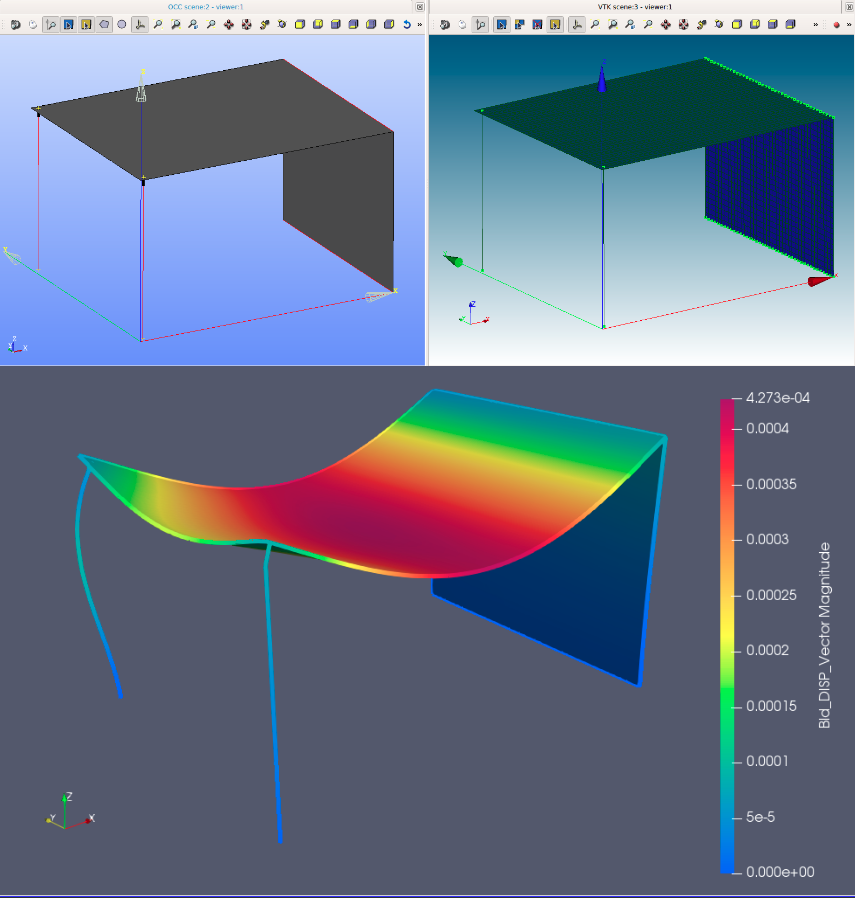
Support for connections between slabs, walls, etc. has now been added in ifc-to-code_aster and two examples added in the analysis-models.
The examples are created based on a script that does the inverse operation of the original script, taking as input a json file and returning the structural ifc file.
A single slab
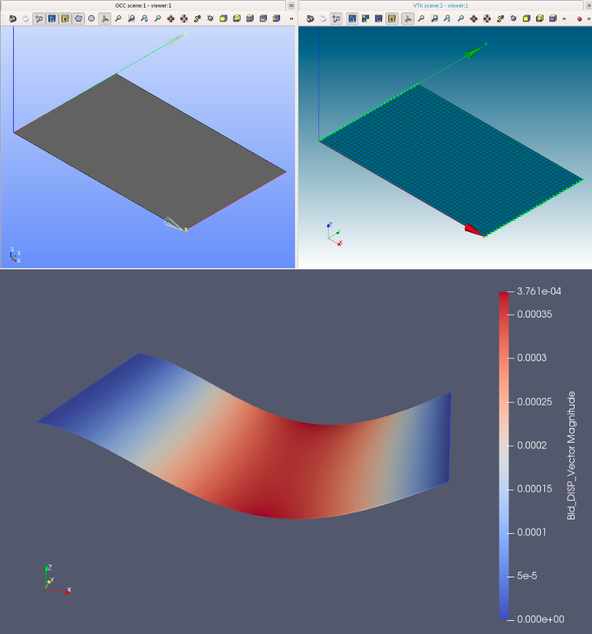
slab_01A simple structure
structure_01The IFC files from Advance Design did look incomplete.
Is your workflow something like this:
I see that @moult is working on an ifcsverchok blender add-on. I'm looking forward to the day when I can generate a structure in Sverchok with all the relevant IfcStructural elements ready for analysis.
@brunopostle yes that is plausible workflow. Loads can definitely be in the IFC file as well, except for seismic which are not considered, but other than that typical static loads, loadcases and loadcase combinations I believe are considered. Loads are next in line regarding my work after implementing also surface connections and refining the algorithms for all connections in general as at the moment there are some limitations in what I did for curve connections and I am trying to overcome those for a better and straight-forward usability.
IfcSverchok looks promising but a structural engineer/developer has to step in to implement ifc structural, Dion cannot do everything, and the same would be needed for BlenderBIM also as at the moment there has not been much progress at the UI level for structural analysis concepts. I would be willing to work on this but I wish I could have also at least another person that helps, my experience in blender is minimal and I do not want to undertake too much and not deliver, given also the work needed for ifc2ca. Let's see how things evolve :)
I've created a page for documenting and/or linking to this work https://wiki.osarch.org/index.php?title=Structural_Analysis_Format_(SAF)
hello everyone. First off, I am fairly new to OSArch and find all of the projects from BlenderBIM to integration with code_aster, etc. quite simply amazing to the opportunities it presents. As a structural engineer (who knows rudimentary Python programming), I'm quite interested in finding a suitable workflow for perparing input files from IFC for structural analysis. @Jesusbill I'm not so familiar with IFC nevermind ifc structural but in my spare time I'm going to start learning what I can on how to use BlenderBIM to author ifc files and I'm sure at some point I'd be able to help out with providing feedback/ideas on structural analysis concepts at a UI level. Not sure how much time I will be able to spend on this at the moment. Also i am thinking that a "IFC to code_aster to IFC" workflow would be amazing but tend to think that rather than writing the whole results for each 1D or 2D element it would seem better to me to also evaluate the analysis results in terms of the plausibility of the geometric parameters within the structural analysis round-tripping "IFC to code_aster to IFC" workflow. As documenting the results of the code_aster analyses seems to be separate from collaboration of let's say the architect and the structural engineer. anyway just want to also comment on reading through the whole thread that the progress so far kind of blows my mind. to start if there are things which I could help with I'd be glad to give it a try despite me being quite new to how these "workflows" work.
Hi @jchkoch ! Great to have you here and to have your support.
At the moment we are still developing the very basics for authoring structural analysis models in BlenderBIM, I think we will need a couple of months to arrive at a point that we can have a basic workflow (create members, connections and supports) to test with users, but I will definitely post in the forum when this time comes. And one reason is that we are do implementing basic stuff now but I reckon we will have to go over a second round after to polish some aspects that are important to effectively apply structural engineering. I am thinking of showing/implementing units for all quantities, proper orientation implementation of local axes, limits on the property input values and other "details" that we are leaving behind for now .
Regarding your statement:
I imagine your are simply referring to verification of the structural elements right? I certainly think that this would be a great and very important task that completes the cycle of the structural engineering work, apart from drawings and documentation. But for that we would need more resources to do it now, I see it more feasible once we have the possibility to create and to run the model.
Well to be honest there has been a setback at some point as there are no valid authoring software to create the models. My initial work was based on the pipeline after the model is authored, which we will find handy in our next step, the analysis implementation.
I think there will be soon some tasks we could need help, other than user testing the UI when it's the right time.
Talking with @krande yesterday we do want to start building some profile/section and material libraries, for example for steel profiles and for concrete/steel materials, which would be great to have them as IfcProjectLibrary (right @Moult ?) that can be used to directly select materials and profiles in BlenderBIM. We have to set this up, but I definitely see potential work for non-coders engineers there, in compiling tables with all needed information to create the libraries. We will post more info on this when it gets started