

[Blender & ArchiPack] A detailed review on using Archipack for architectural drafting

A little disclaimer, since Archipack's original intent was for visualisation, not architectural drafting, but I thought I'd give it a spin, since I assume that's the goal - for Archipack to be the best architectural modeling tool in Blender. I had been doing more bespoke buildings and never took the time to try out Archipack in detail to see if it could replace the type of larger commercial drafting I was used to. Here are my observations. Some are similar to bugreports, some need further fleshing out. I hope this can help polish Archipack!
Pinging @yorik and @theoryshaw who are also architects who can perhaps tell me if something I'm looking for is unreasonable :)
Ease of use
I did not notice shortcuts to create walls, doors, etc. We need shortcuts when we draw! Also, to create a wall / door/ etc takes two clicks. The first click to click the wall button, and a second click, a significant distance apart from the first click, to click the desired wall type. This should be reduced to one click (and therefore one keyboard shortcut). This may sound like a small issue, but I guarantee it is not for a seasoned drafter!
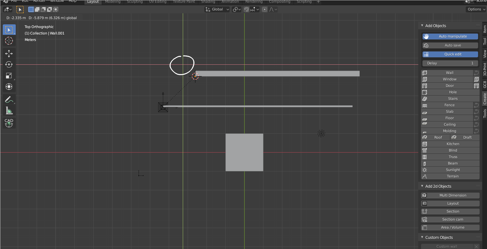
Also, when I click the wall tool, an X and Y axis appears on my screen where my cursor last was... but when I move my cursor, the XY axis intersection doesn't follow my mouse. Is this a bug? See screenshot below where I've circled the XY intersection.
Also, I cannot zoom or pan in this mode. Can this be possible?
Grids
Is there a grid object? Many designs have this restriction to start with.
Wall types
Out of the box, there is an "Inside 10x240", "Inside 15x240" and "Outside 30x240". Wall presets. Putting on my architecture hat, there are a few things concerning me. There are two usecases I'm looking for:
- In concept stage, I have not yet determined wall types. Therefore, I'm looking for generically sized, floor to underside of slab above walls (so that in a section cut, I don't see walls that don't go floor to floor, which does occur, but generally not a detail considered in concept stage). These generic walls are for spatial planning, and are unlikely to have materials determined yet.
- In any stage past concept, I've determined wall types, so I want to create my own wall presets, and stick to those.
So the presets are nice as a demonstration, but not practical for the concept stage. 2400mm is not a typical floor to floor height, so is too short. The use of the words "Inside" and "Outside" are misleading, as you may indeed have outdoor walls being 150mm (e.g. shopfront glazing) and indeed have indoor walls being 300mm (e.g. to capture structural columns). Typically during generic planning, you look for 3 or 4 generic sizes depending on the topology: like 50mm (toilet partitioning), 100mm or 150mm (indoor non-structural partitions), 200mm or 250mm (inter-tenancy walls, block walls, particular fire rated or acoustic treated walls), and 300mm or 350mm walls (structural walls). Can I recommend adding generic walls, perhaps at 100,150,200,250,300 sizes?
Once concept stage is done, for larger projects (note: less of an issue for smaller projects), it is important to bulk select and manage walls of a particular construction type. So if I click a wall, I should see very prominently what type of wall it is: a Generic 150mm wall, Generic 250mm wall, etc. I did not see this function. In the IFC world, this links to a "IfcWallType" relationship. Therefore, if I then change a property of a single Generic 150mm wall, then all other Generic 150mm walls should also inherit that property.
In short, clicking wall should prominently display whether or not it is a single bespoke wall, or if it is part of a wall type, and what that wall type is. Ideally, if the BlenderBIM Add-on is installed, then it should show the wall type IFC relationship too.
Door types
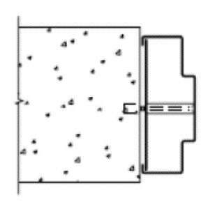
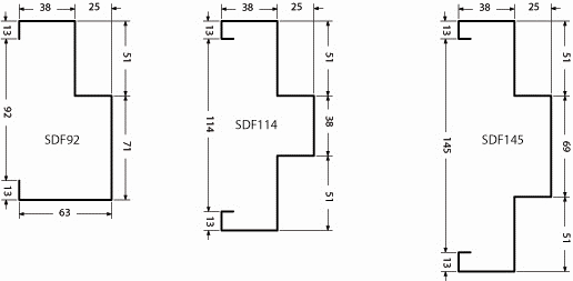
It would be good to be able to have support for steel door frames. Here's a generic one I found online, that I've marked up in red how the wall is inset:
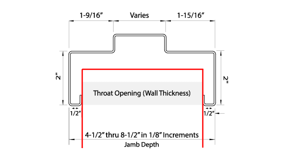
All the dimensions in that are actually variable, and some can be zero. For example, see the image below where there is only a single, not a double rebate:
Similarly, it is important to note to relationship to door and wall. This is important as it determines how you schedule the door opening. In the first picture, I drew the frame overlapping the (supposedly partition) wall. In the picture below, however, you can see it does not overlap (also for stud wall):
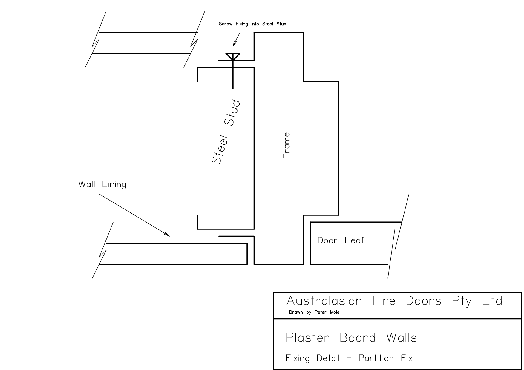
In concrete block walls, very common in commercial designs, steel door frames may be face fixed as shown below. Note that if it is face fixed, there needs to be a parameter to determine how far inset it is in the wall opening.
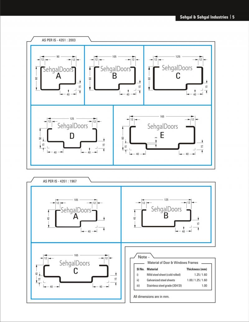
Steel door frames generally can be satisfied by parametrically creating that shape I showed in the first picture, to form the variations in the second picture, so hopefully it can be supported :)
One more picture :)


Comments
I relate to how you describe initial wall type parameters, typical usage from concept design and how to transition to later stages.
In terms of the relationship between walls and doors (or windows, structures, ceilings and floors, and so on) I'm always put down by the standard or inflexible way software forces our modelling. I like to customize my own details and that's the kind of flexibility I find in my current software, SketchUp. It's one of the things that makes suspicious of BIM modelling. Is there some BIM software example where architects can define or parametrize in detail how a door intersects with a wall and then apply that to all doors of the same type? And if so does a type have to change if the wall it's inserted into changes (For instance from a concrete wall to a multilayered wall type)?
Nice that you created this thread, it should be a useful resource for Archipack developers. Hope you don't mind me adding my own experience from using it for a live project.
My observations are more at the workflow level and not as granular as stuff you've addressed. Archipack is indeed fast as advertised for architectural modeling and concept development and the amount of thought that has gone into it shines through, the more you get to discover it's nuances. I had a few gotchas though that slowed me down. Some time spent reading the backlog of comments of the Blender Artists thread for Archipack sorted some of the issues out, while Stephen was kind enough with answers to others. Given that everyone would be coming from workflows and practices they are accustomed to with other tools, I think it would help to have a repository of tips for using Archipack. Here is a spread sheet for example, which I started to archive lessons learnt from my own experience and from feedback from Stephen, though these may change as Archipack gets developed further.
I lost a lot of time getting svg exporting to work right. I'm aware the entire 3d to 2d workflow is being worked on, but my experience coordinating with other people who don't use Blender is that a lot is hinged on the 3d to 2d workflow being seamless. I would typically export to SVG, edit the svg in Inkscpape for proper communication and then send the output from Inkscape out for feedback. When the feedback comes and I return to work on the model in Blender, all the time spent editing in Inkscape would be lost as I would have to repeat the same steps over again. It adds up to a lot of time, especially if you have to go back and forth a few times and I got complaints about time lost due to this workflow. I'm really wondering if Grease Pencil can be hacked to replace the 2d line work that would have been done in Inkscape, so the workflow becomes that you generate a 2d plan same as you would a section, add a Grease Pencil layer on top for more line work, sketches and annotations, export all that together to svg for feedback, receive feedback, implement changes on the Blender model, press update plan to update the 2d plan, edit the Grease Pencil layer you set up on the first pass and export to svg for another round of feedback.
Lastly, I had quite a setback with walls not being straight and had to re-draft all the walls in AutoCAD. Perhaps I could have done a better job of constraining my walls while modelling in Blender (toggling F8 in AutoCAD does this effortlessly), but I assumed they were straight while most of them were off when imported to AutoCAD. The redrafting cost a lot of time.
I've seen drafting can be done in Blender, I do limited drafting using curves, and the CAD Transform tools and other tools make this more precise, critical gaps in the workflow however need to be plugged- lineweight, linestyle, layers, (Grease Pencil has these), etc.
@JQL just a note that you don't need to use Archipack if you don't want to. In Blender, just like SketchUp, any shape can be any BIM object, and we've designed BIM data (BlenderBIM Add-on) and geometry generation (Archipack) to be separate, so this allows us to either manually draw with 100% control, or use any tool we need to get the parametric behaviour we're looking for. Archipack is one of the options, which I describe in this thread :)
@DADA_universe I haven't yet come across issues on walls not being straight. I think that's just a modeling issue. But I'll keep an eye out for it!
I mocked up what I think the "add wall" wall type selection window should look like by default. Note that these are for metric standards, and I purposely omitted the wonderful world of partition walls and only provided a single sample. If Blender is set to imperial units, it should probably default to imperial standards (e.g. a 4x2" stud wall), but for metric, I believe what I've put in the image below are safely generic to be used as a starting point for architects. I think it is relatively easy to do and will add a lot of value. @stephen_l just a note: if I put there brick/block wall, or stud wall, I actually do not expect Archipack to generate each individual brick or stud. In fact, I want it not to do that by default. It should simply set the materials and overall size correctly. So all the functions to create it already exist, I'm just proposing to add it to the presets.
Later on, there can be additional tools to generic studwork or count blocks / bricks (calculating cut bricks and rationalising to brick dimensions is important when designing), but it is not necessary when supplying these presets out of the box for now.
Hope it makes sense.
Here are a list of wall thicknesses for each. The height should be changed from the current setting of 2400mm to 3000mm. There is no "best" default height, since it depends so much on what you're drawing (here, apartment floor to floors are ~3100mm minimum, commercial ~3500, retail can be ~4000). However, 2400mm is definitely too short for most things, unless you're drawing partition walls in wet areas. So I propose 3000mm.
If you want to build a feature that has country presets, that would be ideal and we can provide more "correct" presets, but until then... hopefully these presets get you more "in the ballpark" for architectural users.
A fundamental premise here is to separate walls by trade. The trade is a fundamental piece of metadata which can be used for many things like costing and environmental analysis. Please other architects correct me, if my experience is not shared :)
Another usability issue I'm finding. If i want to create a 90 degree wall segment, it is quite hard to click on the degrees number (circled).
The numbers circled in blue are difficult to see. I don't need to click them very often, so it's less of an issue, though.
Three more additional issues:
1) use ALT + enter to change a value on all selected objects
2) save your own presets, they will last on update.
3/4) Yes, expand "Steps" parameters in "Parts" tab, wood on steps is only made of materials.
1 Enable "Interface: Copy Attributes Menu" addon, then right click over a value and use "Copy to selected".
2 Must definitely provide default sets according regional preferences (and unit system...), here doors are 2m height by default.
There is a tool to share presets in "File->Import/Export->Archipack presets (.apk) - basically a zip of user presets folder.
Another issue about handrails - railings are measured from the top of the stair nosings to the top of the railing profile - this is an incredibly important dimension to get right as it is a legal requirement. There is a tricky issue with this, since if an architect wants to draw a 180 degree turn stair, the only current way I see to draw it is by drawing two straight stair flights separately. The issue is that the landing height is halfway, but if I create two flights with half the floor to floor, I get this:
It's quite hard to explain some of the issues here in text, but here's a straightforward one to start with - stair heights are to be measured from top of landing to top of landing:
The issue with stairs is geometry under the steps, in your sample you are using the 1st step as part of the landing.
So move your stair from 1 step up and measure become coherent.
At this time, handrail altitude is measured from bottom of step, will take a look at change this so it is measured from step instead.
So the idea is model anything and classify it. Right?
That's the SketchUp take on IFC too though it seems way less organized than yours.
Is it possible to have automatic classifications with Archipack?
And for experienced modellers is it possible to create different presets for windows and doors and such things?
And can Archipack/BlenderBIM be somehow associated to parametric modelling tool's geometry as input or output, already with BIM info, on sorcar or sevchok? Sorcar seems to be people's favorite.
Archipack provide basic classification for objects, either on the fly at export time when missing or as static data using single click project wise operator.
You are able to save presets for all archipack entity, it also is possible tu use custom geometry as openings (window / doors) and for walls.
window generator video
For regular blender objects (whatever the generation method) you must rely on blenderbim tools to classify.
@stephen_l ah yes, sorry, I think you are right, I'll take a closer look.
@JQL correct - model anything and classify it.
Note that classifying things as walls and doors is just the beginning. The real value comes from additional metadata like, what door type it is, or what wall type it is, what fire rating, acoustic rating, and so on. If you are working on a larger project, you will need both Archipack and the BlenderBIM Add-on :)
Experiment with Grease Pencil + Archipack with a digital pen and drawing tablet. Grease pencil speed guides are helpful in constraining lines drawn to a circular, radial, grid and other constraints. The grid guide gave some performance issues, but that can probably be chalked up to wrong usage. Archipack walls were generated from curves after converting the Grease Pencil stroke to curves. Still feels a bit rubbery to use, but seems to have prospects for a quick work flow for progressing from concept sketches > 3d form studies > finished models. It would be an added benefit if you can easily go back and forth between those stages without breaking something.The ability to sketch out your design as you would on paper without losing any of the detail (as would happen if you scanned and then traced over it) would help mitigate one of the main criticisms leveled against CAD software being used for early stage design work - your design being restricted by the mechanical drawing parameters of the CAD tools.
This is really worth exploring at a conceptual level. Cool possibilities indeed!
Implemented support for grease pencil strokes in "wall from curve" tool.
Really like what is happening here..
Some of these posts really have value, both for learning How To, and as a good basis for advancing development.
It is my sincere belief that we should try and organize some of these in wiki pages.
@duncan do we have, or could we have a sandbox in the wiki. As @duncan has stated before, a lot of stuff is evolving fast. Even so documenting and structuring has never been a bad approach.
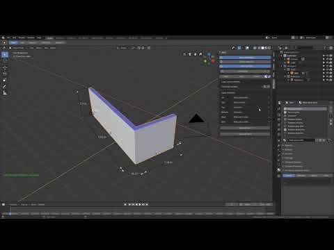
Have been investigating pure box modelling and utilizing pure Blender functionality. After some trial and error found it to be very efficient.
@CadGiru just go ahead and make the pages you think make sense and add them to some relevant categories. If we're missing some categories let me know and I'll make them. At the moment there are not many templates and infoboxes but they're slowly evolving, I'm just learning how to make them and have limited time. I'd welcome any help.
I have been reading this thread, but maybe I read over it. But is there in Archipack pro already a keyboard shortcut for adding a wall?..
And how does one add a custom object to the archipack library? It works wonderfully with walls, but with windows and doors I get confused
I found this tutorial:

But it's far too advanced for a complete beginner as me. I am still learning Blender as well.
My wish I can update custom objects like in Blender like I would do in Revit,
for example, I would like to swap out the window framing profiles and panels in a custom blender object with own predefined profiles. don't know if this the correct workflow or it's meant differently in Archipack?
And another question, is there maybe a tutorial on how to define materials and make a material library in Archipack PRO? While keeping in mind these materials will also be used in IFC.
"Custom" geometry based windows / doors you can save as presets will be part of upcoming release, and are available in current beta 2.3.94.
Basically you may model the way you like / import objects from eg sketchup warehouse's website as long as the result is a mesh with vertices. Then turn into "custom" object by assigning vertex to groups so they either move or scale when you change the size of main object using a dedicated modal operator, and use this custom object as "custom mesh" in window object.
Archipack material library file are regular blender file, so basically you are able to create your own with any property you like stored on material, however due to the nature of blenderbim i can't see how you'll manage to get ifc information from merged file into "live" .ifc file data without further processing material at load time.
The loader will look at your scene for a material with the same name, and if found, will re-use scene one instead of loading from file.
The trick to create a library by hand is to set a "fake user" to materials so they are not deleted even when not linked to any scene - so basically the file will only contain materials.
As objects may use many materials, archipack implements a concept of "material set" basically storing many material names to load when you select a given set.
When you save such set of material for any object, archipack does save the materials into the library.
Why is there no "apply offset" button for slabs? Would be very convenient for creating cavity walls in an insanely fast manner. Or maybe I am using Archipack PRO wrong. I have the feeling I am using Archipack PRO now in a bit of a hacky way.
My aim is to create foundation footing with a slab and an insulated cavity wall. Would also like to see an efficient way of cutting voids/openings through all three walls, and when modified have them exported to IFC as well.
Archipack still does not implements layered walls representation, as blender boolean's fast solver is not able to properly handle properly situations where layers are touching, and exact solver is painfully slow.
Openings wall's detection only take a single wall into account, it is also an issue with holes in ifc, where a single global hole can't cut more than one entity.
You may rely on wall's offset + apply instead.
When I use the offset function it works well, but when exporting to IFC I keep getting the following result, see images.
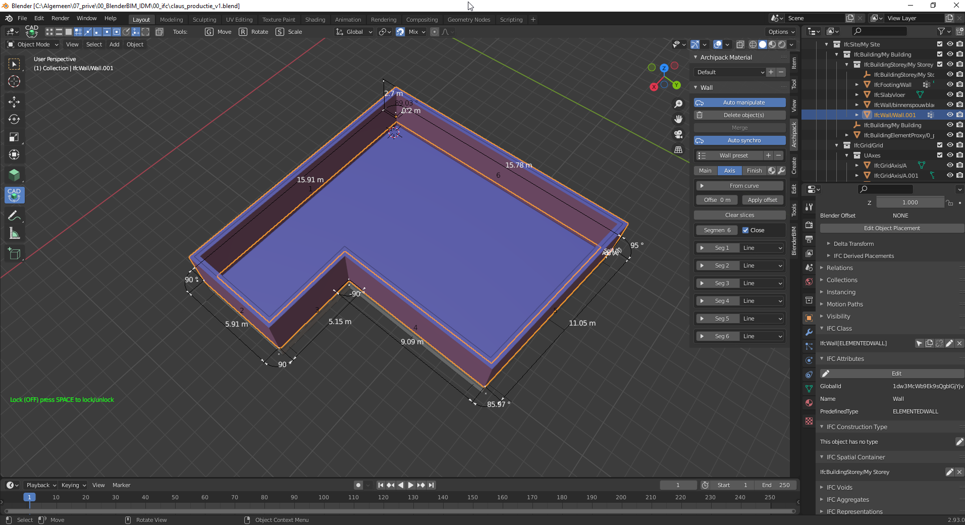
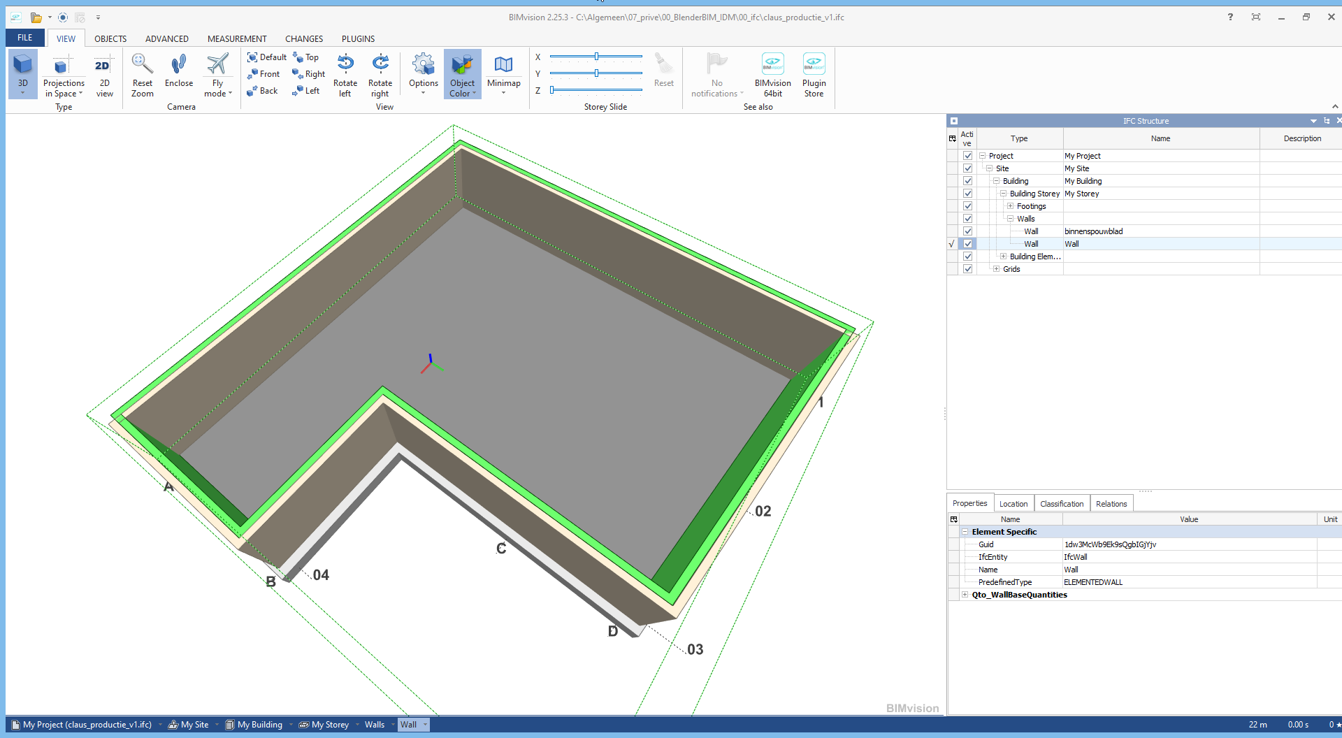
Should work in latest archipack beta (2.3.95)
How do I acquire the latest version? I have to purchase an update? I filled in my e-mail adress in the website:
https://blender-archipack.org/archipack/update
but I keep getting the 2.3.6 version of Archipack I already have. Maybe I am doing something wrong.
For latest beta, use
https://blender-archipack.org/archipack/beta
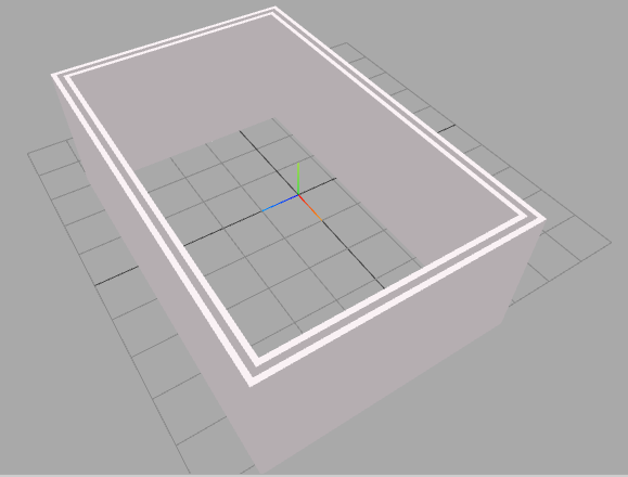
When trying to create a wall I got this bug, what I am doing wrong?
What's the roadmap for a shared collaboration between Archipack and BlenderBIM? Archipack has really great tooling, can't the draw wall functionality of Archipack be incorporated into BlenderBIM, so one could start drafting with IfcWallTypes for example?
Ping @stephen_l :)