

Create a prefabbricated IfcWall with IfcBeam at top

Hi there!
I've to create a long wall with a beam at top.
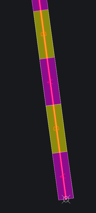
The wall is prefabricated and consists of two alternating elements (A and B) to which I wanted to assign a different IfcWallType. Is there a way to generate the wall quickly? It's 600 metres long :D
I would like to divide it into the two types.
Any suggestion?
Thanks!
Dennis
Tagged:
Comments
@mastrolube
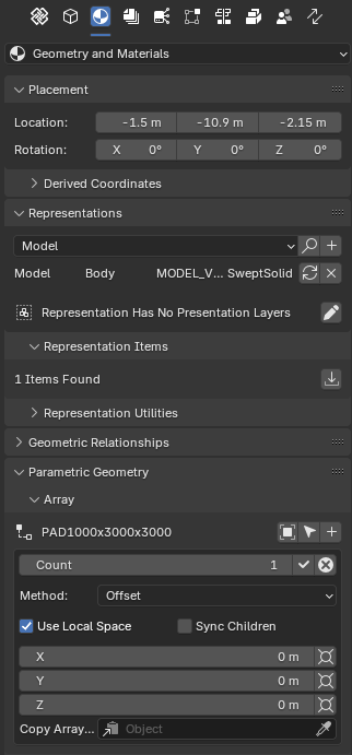
did you try array?
mind you, the array settings do not save in the .ifc file
Also is it possible to follow a line?
good point
array doesn't seem to have that option apart from "distribute" and "offset"
I tried using modifier > array and curve in blender to duplicate along it but doesn't seem to work with IFC elements, maybe someone here knows the solution?
ouch :(
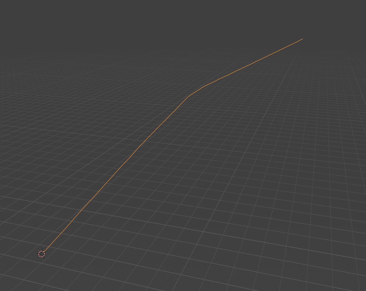
I imported that axis from another program which is georeferenced. I'm at coordinates 440000; 5000000 and I can't even select points here, it always starts from the origin (I think). :((
If I am close to the origin I can select the points without any problems.
When I press ADD, it looks like the first item is already selected and it's very distant from my location :D
@mastrolube
I work with big coords too (UTM30N) but use georeferecing settings (see image), the model itself works in local 0,0, as far as I understand Blender doesn't like big numbers too much
The Blender's Array modifier doesn't discriminate Ifc elements, it should not follow the shape of a curve, to follow you would need another modifier
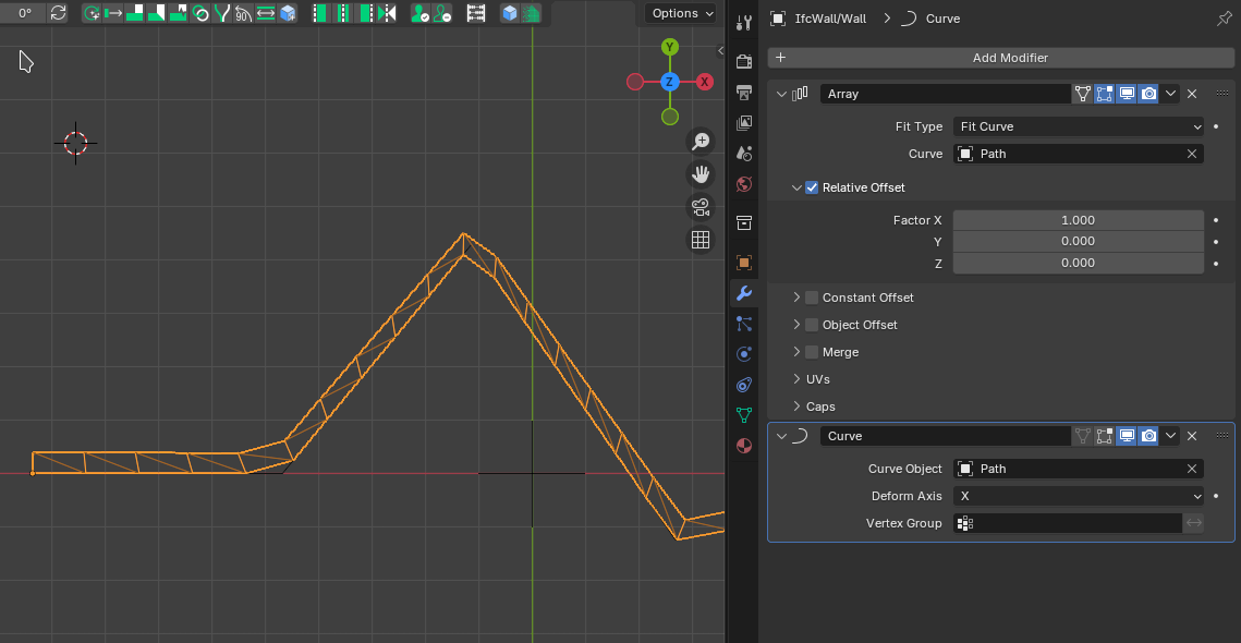
Deform -> Curve, however it really deforms the mesh :-)Hello!
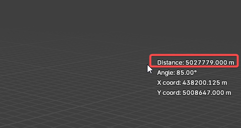
So your suggestion is to extract the coordinates of the starting point of this line and create a projection with this value and then I import my dxf object?
@mastrolube
yes, but you also need to measure the angle to make sure its orientation is according to your georeferenced plan
hope it helps
I might be missing something, but i think they do...
@mastrolube If you search IfcAlignment in the forum you'll see the beginnings of a funtionality that could address this idea of repeating things along a path.
As I understand it, Bonsai can 'view' these configurations, but there's currently no UI to create them, and/or modify them in Bonsai.
@civilx64 @Rick_Brice would know the most. :)
I think the following issue speaks to this projected roadmap: https://github.com/IfcOpenShell/IfcOpenShell/issues/4933
Correct - Bonsai can read the IFC and process the geometry, but not UI for authoring. You can probably layout based on alignment and linear referencing from a python script. Some discussion and examples are discussed here https://wiki.osarch.org/index.php?title=IFC_-_Industry_Foundation_Classes/IFC_alignment
@theoryshaw
>
you're absolutely right! I don't know why last time I checked it didn't but I am happy to be wrong, the array settings are saved in the .ifc file
thanks
@theoryshaw please, is there a way to use
Parametric Geometry > Arraywith IfcElementAssembly?I tried using the box
Sync Childrenbut couldn't understand its practical usethanks
Nope. :)
https://github.com/IfcOpenShell/IfcOpenShell/issues/3806
@steverugi When you make any changes to the array's parent object and want these changes to be applied to all the children objects, you must have
Sync Childrenon when editing the array.thanks @bruno_perdigao
but I can't manage to array IfcElementAssembly elements, it only affects the empty
I don't want to duplicate elements inside an IfcElementAssembly using Array, just duplicate them (like a truss multiple times)
any hint please?
@steverugi Sorry, I think the way I phrased it was misleading. It doesn't work for aggregates. I was just explaining how
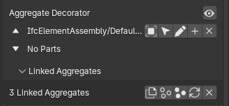
Sync Childrenworks with single objects. In that case, "parent" means the original object and "children" the copies.If I understand correctly, the way to achieve what you're describing is by copying the aggregate and moving them manually, unfortunately. You can do this by pressing "crtl + shift + d" or by using this panel:
@bruno_perdigao
Ok that one I know it ;)
Thanks for your reply
Hello everyone!
I think I have made some progress...
I am importing my dxf axes for walls and generating cubes and deforming them to have the correct wall geometry, after which I am manually applying the IFC class IFCWall. The problem is that when I apply walltype to wall it moves away and returns to a cube. What am I doing wrong?
Any clue? Thanks!
@mastrolube
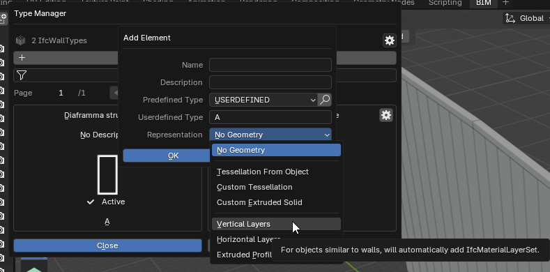
I think you can create 1 type of retaining wall "diaphragm" by defining its thickness 800mm and adjust height (26m) and length (2.5m) according to your curve from the top bar menu.
Such wall has its own IfcWallType and its instances can be Shift-D to replicate one next to the other to form your model
Hello!
Can you please show me what do you mean?
I have created the two walltype from here:
Sorry!
Grazie!
CLIP
Ok thanks! This is the slow way, but I need to do this for hundreds of elements, so I've written a script to generate these walls to follow a curve, and the script works quite well. The problem is that when I apply a typewall to them they change their position and heigth. I think there's something wrong with the wall type I've defined, but I don't know hwo to fix it :(
@mastrolube
coding is beyond my reach, maybe if you post you script here someone can come to the rescue