

IfcEarthworksCut/Fill now with automatic QTO

Another magic peformed by @Massimo today:
In IFC4x3 we can use IfcEarthworksCut (and Fill), which can be for both infrastructure and residential projects.
With today's release it's now possible to automatically generate Qto_EarthworksCutBaseQuantities
In the gif below you can see the following steps:
- have a solid (IfcGeographicElement.Terrain) able to receive a void
- add an IfcFeatureElement IfcEarthworksCut using the terrain as Featured Object
- use Custom Extruded Solid as representation (but you can use "Tessellation from Object" if you have one)
- edit the void using "tab" twice to go to Ifc Item Mode > Ifc Edit mode
- adjust the polyline definining the boundary of your cut
- check the Depth, "tab" again to enter to "Ifc Item Mode" if necessary
- Alt-O, with the terrain selected to exit and visualize the "excavation"
Quantity take-off is as usual, select Blender engine to perform it, it also applies to IfcEarthworksFill
Nice one @Massimo, many thanks again
Tagged:


 and 5 others.
Comments
@steverugi thanks, but i just mapped the calculating functions :-)
The real magic is the huge work done by the developers that allows to easily contribute to the project in a very efficient way!
Thanks again @Massimo.
I guess I missed something. How do I keep IfcEarthWorksCut visible and selectable in the outliner?
To assign to a task I need to select the element. Or is there another way?
@walpa
Alt-O, with the terrain selected for visualize the "excavation". It is the same to visualize an opening in a wall for example.
@Massimo, ok, understood, thanks.
In IFC/Bonsai, it is possible to apply the Boolean difference/intersection operation to obtain the IFCEarthWorksCut on a real topographic solid?
not sure this is the best approach but you can use an object or an IfcElement
in this example there is an IfcGeographicElement.TERRAIN and an IfcColumn
to create a void as IfcEarthworksCut based on the boolean between the terrain and the column I would use "Tessellation From Object" and select the column
result:
if I hide the column:
Thanks @Steverugi,
The problem is that with that method in Qto_EarthworksCutBaseQuantities/UndisturbedVolume we get the total volume of the column, we don't get the volume of the excavation.
@FranSeoane
good point, in this case you need to edit the void defining the cut and adjust its vertices
not an ideal solution though
I tested it and came to the same conclusion, the ideal would be for the void to be created from the boolean difference.
The position of the void is also not updated if the base object is moved. It requires manual work.
For now it is already a great tool!
In the future, perhaps a way to recalculate the element (mesh and position) like the "Operations" button in Window Tool.
Excellent.
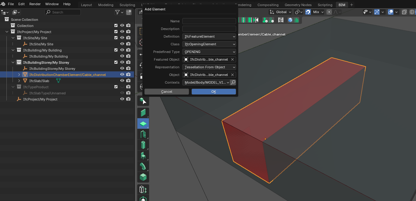
Can the IfcDistributionChamberElement work in the same way ?
I am thinking of an entity that sets FORMED DUCT on a slab.
@KoAra, I don't think that seems to be the case, if I understand the documentation correctly, IfcDistributionChamberElement is not an "empty space" (like a excavation looks like after its execution), but a place where part of the system is located.
It inherits from IfcDistributionElement and not from IfcFeatureElement like IfcEarthworksCut.
@KoAra
I think you could use your distribution chamber the same way I used a column in the example above to create a void in the slab.
In similar cases (cable through) I'd add a polyline in the shape forming the same slab instead.
Much depends on your geometries.
Like this?
What did you mean by "real topographic solid"?
Real topographic solid: the volume of a surface with contour lines ("Toposolid" in Revit).
In a simple prism, it's easy to fit the volume of the IfcEarthWorksCut to its faces, but with a surface defined by contour lines it's necessary to obtain the cut volume using a Boolean intersection operation.
@walpa , @steverugi, Thank you for replying.
IfcDistributionChamberElement entity inheritance is IfcDistributionFlowElement, IfcDistributionElement.
However, IfcDistributionChamberElement is allowed to be used as empty space for placing Pipe, etc.
Pset_DistributionChamberElementTypeValveChamber describes a chamber that houses a valve(s). I think the MEP designer would place IfcPipe and IfcValve in the empty space of IfcDistributionChamberElementTypeEnum VALVECHAMBER.
I am hopeful that Bonsai will make it easier to model MEPs in Industry :)