Probably are the german VDE rules the most restrictiv in the world. Each cable has within its wires a green/yellow wire for 'ground' and a blue wire for 'neutral'. So your cables are named NYM-J-3x1,5 for single phase power distribution to a sink (light bulb f.i.) ( N = Normenleitung, Y = Isolierung der Adern aus Polyvinylchlorid (PVC), M = Mantelleitung, -J = mit grün-gelbem Schutzleiter, 3 = Anzahl der Adern, x = "mal"
1,5 = Leiterquerschnitt in mm2) (see https://de.wikipedia.org/wiki/Kennzeichnung_von_Leitungen_und_Kabeln)
When I say Cable , i mean a set of wires . The directionality is not required for any cable (but probably helps for some checking routines from the used software).
Then they are different levels of modeling.. in fact the 'electrical engineer' does not have to model each cable to each 'switch device' and 'sink' or 'plug'. He has to know which cable length of which cable type is needed for the installation and assign it to a distribution circuit number in order to make a good Quantity list which then will be 'priced' by the contractor. The contractor (electrical installation enterprise) will have to complete the 'engineers'-model with a detailed 'montage-plan' ('installation plan'). The contractor has some freedom to redefine the cable paths and even some conduits/carriers paths. But the engineers duty is to deliver a working (collision free) configuration for the whole electrical distribution system. So wall openings for carrier-systems are usually already defined in accordance with the architect, who has to coordinate the technical feasability of all systems in provenience of all the technical installations (heating, air, water, electricity (heavy duty/power), electricity (security, controlsystem,sound...))..you name it..
Here comes the Fill-Ratio for carrier-systems. They can hold only a limited amount of cables (because of weigth or just space).
The way DDS-CAD (now Graphisoft) use to handle those carrier-systems was to register each cable running in the carrier at each input/output port, and like this, knew its filling-ratio at each point in space. cable were not modeled as cylinder in the carrier, but only a squared volume representing the amount of cable (filling ratio).
Where can I see the IFC scheme for the electrical devices.. there are omniclass, etim.. and probably many more classification systems.. our library should try not to reinvent the wheel..
I downloaded a IFC4 piece of carrier from 3dfindit.com.. but windows was not able to extract the zip container as the filename was too long.. an example not to reproduce.
Ports for cable carriers may be connected using IfcCableCarrierSegment and IfcCableCarrierFitting. Type objects for cable carrier segments and fittings (IfcCableCarrierSegmentType and IfcCableCarrierFittingType that are not specific to a particular system type may have ports with PredefinedType of NOTDEFINED which indicates that occurrences of such objects may connect to ports of any other cable-carrier based port. Valid enumerations for cable carriers are the same as that for cables, and may be asserted if ports of the contained cables are all of the same type.
The top diagram in Figure 6.2.3.8.A for IfcDistributionPort shows a Pipe case, but the Realizing Element in IfcRelConnectsPorts specifies IfcCableSegment.
The diagram in Figure 6.2.3.9.A for IfcDistributionSystem does not use the Realizing Element in IfcRelConnectsPorts. The main IfcDistributionSystem relates (contains) the branch IfcDistributionSystem using IfcRelAggregates.
How should Cable Segment, Cable Carrier Segment, Ports, and the system be related as IfcSharedBldgServiceElements?
Pset_DistributionSystemTypeElectrical provides items that could be useful for cable size calculations. bSI seems to consider electrical issues, but it's difficult.
you are not alone, while I have only gratitude for the team who put together the documentation, sometimes I silently cry when I try to decipher its content. But I was told it's a good brain exercise to fight Alzheimer, so I carry on.
Ports for cable carriers may be connected using IfcCableCarrierSegment and IfcCableCarrierFitting. Type objects for cable carrier segments and fittings (IfcCableCarrierSegmentType and IfcCableCarrierFittingType that are not specific to a particular system type may have ports with PredefinedType of NOTDEFINED which indicates that occurrences of such objects may connect to ports of any other cable-carrier based port. Valid enumerations for cable carriers are the same as that for cables, and may be asserted if ports of the contained cables are all of the same type.
The way I see it (a bit odd that such specific topic takes most of the description of a generic entity like IfcDistributionSystem) given its nature a carrier may be set as 'agnostic' as to being able to host different predefined types.
The top diagram in Figure 6.2.3.8.A for [IfcDistributionPort] shows a Pipe case, but the Realizing Element in IfcRelConnectsPorts specifies IfcCableSegment.
To me a distribution port is just a connector that can play in different environments but carries out the same role, making elements of a discipline (as nicely illustrated in the IfcSharedBldgServiceElements page) talk to each other. Is there something of the pipe example that you find difficult ?
The diagram in Figure 6.2.3.9.A for IfcDistributionSystem does not use the Realizing Element in IfcRelConnectsPorts. The main IfcDistributionSystem relates (contains) the branch IfcDistributionSystem using IfcRelAggregates.
That one is particularly insidious, my best shot: it's an example of how an external system 1 interconnects using an IfcAssignToProduct via a port part of system 2. Whereas systems and nested systems use IfcAssignsToGroup relationship instead.
How should Cable Segment, Cable Carrier Segment, Ports, and the system be related as IfcSharedBldgServiceElements?
I don't understand the question, if you could please give a practical example
I fully agree with @steverugi, we're all in the same boat....
The diagram in Figure 6.2.3.9.A for IfcDistributionSystem does not use the Realizing Element in IfcRelConnectsPorts. The main IfcDistributionSystem relates (contains) the branch IfcDistributionSystem using IfcRelAggregates.
Consider the IfcDistributionSystem as groups of objects (a main group can contain multiple branch groups) and their objects are connected through ports.
How should Cable Segment, Cable Carrier Segment, Ports, and the system be related as IfcSharedBldgServiceElements?
I think (but I could be wrong) that ifcSharedBldgServiceElements is just a conceptual layer in the ifc schema that groups concepts linked to the MEP domain; it's not an element that is "modeled". Just like ifcSharedBldgElements is a layer where you group the common elements of a civil construction.
@Falkeng said:
1. Cables in Conduits/Carriers: When modeling cables within a conduit or cable carrier, two pieces of information are critical: the path (to accurately measure total cable length) and the fill ratio (to ensure compliance with technical standards).
@lukas said:
Here comes the Fill-Ratio for carrier-systems. They can hold only a limited amount of cables (because of weigth or just space).
I couldn't find any IfcRelationship in the IFC documentation that identifies the cables associated with a cable carrier.
This relationship would be useful for the automated calculation/verification of the fill ratio established in the standards.
Perhaps IfcRelInterferesElements? But I think it's specific to clash detection.
Does anyone have any knowledge of this?
Is there another way, without the need for a relationship?
Thanks
@lukas Vielen Dank! Ich habe einmal in der Schweiz gearbeitet und kann ein bisschen Deutsch :)
That is a very good insight in how to model all this. I can follow the naming and coloring you were explaining as I believe a lot of DIN/VDE is in the CEE and CENELEC so many countries in Europe have a similar setting.
Regarding fill ratio, what would be your recommendation to be as IFC as much compliant? I have seen that Qto_PipeSegmentBaseQuantities provides GrossCrossSectionArea & NetCrossSectionArea since pipes are completely enclosed. However for the case of Qto_CableCarrierSegmentBaseQuantities there is only CrossSectionArea since cablecarriers can also be open. So we do not have a value for the available net space for cables. In IFC4 there is for CABLETRUNKINGSEGMENT Pset_CableCarrierSegmentTypeCableTrunkingSegment with NominalWidth & NominalHeight but that has been removed in IFC4X3 so not a reliable source.
One possibility would then be to compute knowing the type of profile (Typically IfcRectangleHollowProfileDef or IfcCircleHollowProfileDef) the actual net cross section... Any other ideas?
Thanks!
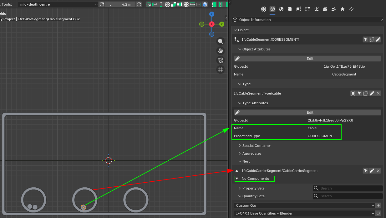
PS: Do you know the difference between CORESEGMENT and CONDUCTORSEGMENT? Core=conductor+its insulation?
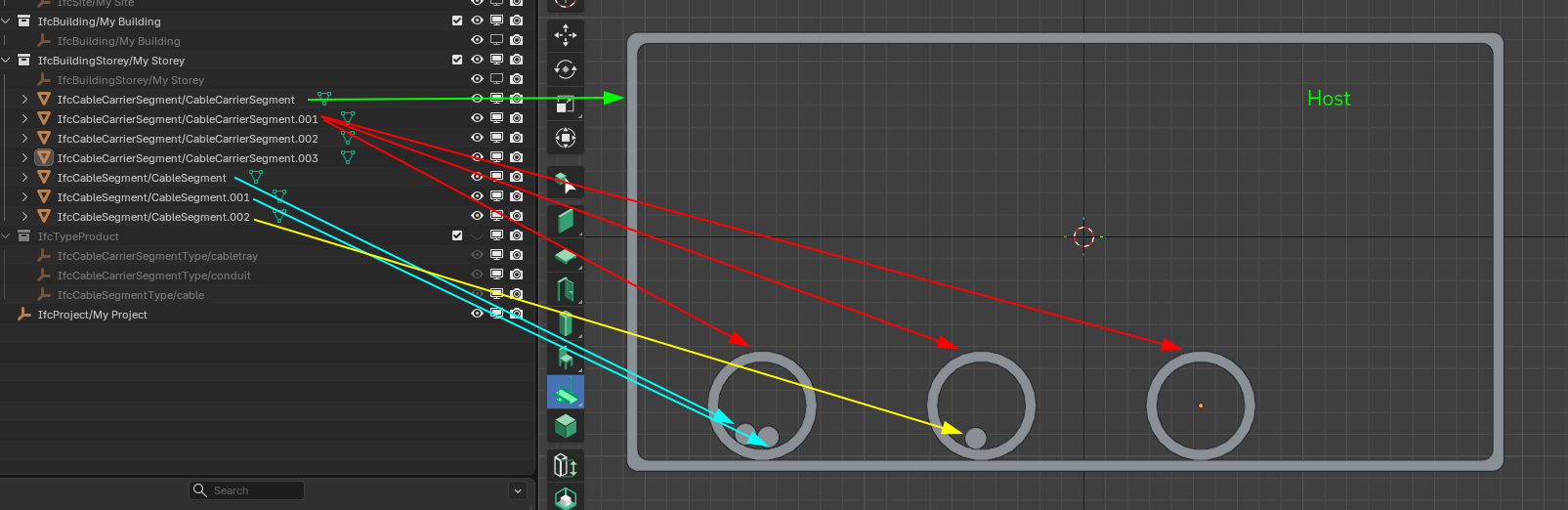
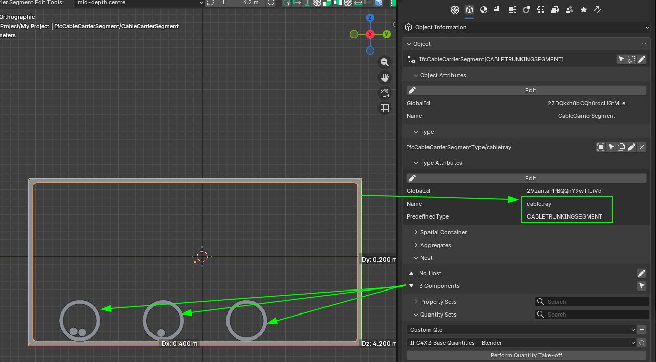
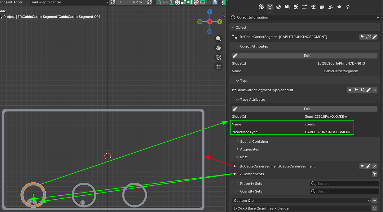
Do you know how is the physical containment done in Bonsai? I mean I have a IfcCableCarrierSegment (from its corresponding predefined type CABLETRUNKINGSEGMENT) for the cable tray (enclosed). Within that tray a I have a number of conduits which are also IfcCableCarrierSegment but predefined type CONDUITSEGMENT. Finally there are a number of IfcCableSegments (of predefined type CABLESEGMENT, CORESEGMENT, etc.).
In order to know fill ratios we must have physical containement established between them. How is this done in Bonsai?
Thanks!
@walpa said:
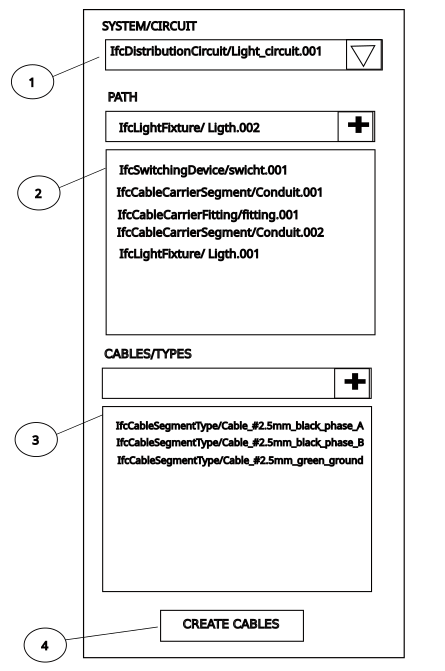
In my dreams, as a user, I would like to have an interface that makes all the work easier for me:
Create the path using the location points of the ports of each item in the order in (2) and for each type in (3) create a cable segment and then assign the created cables to circuit in (1).
The cable modeled with a polyline that could be edited later to:
1 - reposition the cable
2 - increase or decrease the cable size
3 - improve the geometry with fillets, curves or chamfers
4 - separate the cable into 2 segments to create branches (using the appropriate IfcCableFittingType with ports)
Cheers
@walpa I believe this concept is awesome! Let me try to do something around it. To me the idea of making a MEP path builder to explicitly show the IfcDistribution components in order of connection (and down below the ports) is a really nice approach. In the end, these "pipes" start from a relevant port and continue adding untill you end up in a final one. All the intermediate beign segments or fittings which basically need to allign with the z axis of the path... Thanks!
@falken10vdl said: @Moult I have seen you have contributed to IfcOutlet :)
In the comments below from @Falkeng what is your view around cabling in a project vs IFC modeling? I mean from what I understand but I might not be right :) (see the picture of my previous comment) IFC only models energy "flow" not actual wiring? Namely return/ground cabling is out of the equation?
Thanks!
@Falkeng said:
I would like to add another perspective to this discussion regarding cable modeling:
1. Cables in Conduits/Carriers: When modeling cables within a conduit or cable carrier, two pieces of information are critical: the path (to accurately measure total cable length) and the fill ratio (to ensure compliance with technical standards).
2. Exposed/Free Routing: If the cable is not housed in a carrier, its physical geometry becomes more important. We need precise modeling to perform clash detection (evading collisions) and to measure the exact routing length.
3. Connectivity: We should also consider cable connections. It would be beneficial to identify and quantify the termination points and connector types within the model
That can be accomplished with the "Cable Carrier Tool" for knowing the length of the different segments you can get them with Qto_CableCarrierSegmentBaseQuantities (but funny enough the fitting with Qto_CableCarrierFittingBaseQuantities doe not provide length... so I guess "fixed length" fittings are supposed to be used and you can get total length just counting them. Fill ratio... is there a Qto associated?
As @walpa pointed above, here IFC does not help probably enough. As far as I understand all this Distribution systems when applied for cabling, are just a model representation of how energy is propagated.
I believe that can already be done by assigning IfcOutlet?
Cheers!
It is a relationship between the carrier's internal space (cross-sectional area) and the space the cable occupies.
Generally, yes, though this is a simplified version.
I believe it can be done, but I'm not sure if an 'outlet' is the best class to assign to all kinds of connections.
@falken10vdl said:
Do you know how is the physical containment done in Bonsai? I mean I have a IfcCableCarrierSegment (from its corresponding predefined type CABLETRUNKINGSEGMENT) for the cable tray (enclosed). Within that tray a I have a number of conduits which are also IfcCableCarrierSegment but predefined type CONDUITSEGMENT. Finally there are a number of IfcCableSegments (of predefined type CABLESEGMENT, CORESEGMENT, etc.).
In order to know fill ratios we must have physical containement established between them. How is this done in Bonsai?
Thanks!
I have tried with Nests in Bonsai. I guess it is a valid possibility?
@falken10vdl said:
I have tried with Nests in Bonsai. I guess it is a valid possibility?
IfcRelNests documentation:
"Decompositions imply a dependency, i.e. the definition of the whole depends on the definition of the parts and the parts depend on the existence of the whole. The behaviour that is implied from the dependency has to be established inside the applications."
This sentence confused me. Does this dependence exist or not in the case of cables and cable carriers?
I have just seen that Nests allow me to establish a hierarchy of spatial containment... But I do not knwo if there are other ways...
The idea behind is to be able to know fill ratio and check that the paths are correctly made of the corresponding amount of segments+fittings...
@sjb007 Since you have modeled cable trays (saw your comment to https://github.com/IfcOpenShell/IfcOpenShell/issues/7618). What is your experience between IfcCableCarrierSegment and IfcCableSegment? Do you establish any relationship between them to have an idea of fill ratio?
I guess that ideally a sort of IfcRel... type of binding would be best, but I guess that otherwise some PSet with naming relations coould be another option?
Cheers!
@falken10vdl Wooooooahhh there!!!! I think you are confusing me with someone else! :-D The cable trays (more accurately wire mesh cable trays) I'm talking about seeing were about 30 years ago. I sure as heck didn't model them. All I did was lay cable in them as a junior IT guy. Now I'm just a much older nerdy IT guy who got interested in Bonsai for personal reasons. I have no construction industry experience here. Around these parts I like to follow to the old adage "Better to remain silent and be thought a fool than to open one's mouth and put it beyond doubt."
@falken10vdl said:
I have just seen that Nests allow me to establish a hierarchy of spatial containment... But I do not knwo if there are other ways...
The idea behind is to be able to know fill ratio and check that the paths are correctly made of the corresponding amount of segments+fittings...
IFC separates segments and fittings, which makes sense from a product calculation perspective, but it's cumbersome from the standpoint of the port connect system and modeling rearizing elements. Electrical designers must handle both cable segments and cable carrier segments.CONDUIT.
I look forward to your development.
I am sorry but I can not help on any IFC definition or howto.. even if I follow osarch.org for quite long now. never put my hands on.. do not know how 'nested' is then counted for the length of the cable.. in fact, modeling each cable is an overkill.. so they can be needed as IFC , logically in the background to have a BOM, and to know if carriers/conduits still have capacity. The bigger cable (from power delivery starting from ~10 kW) could be modeled. These are also the more expensive ones. The smaller cables can just be counted from the amount of switches, plugs and luminaries installed, with an average length depending on the room distance to the electric-distribution-board.
In Germany, even this amount of switches and plugs in defined in some VDE rules, their z-position in/on the wall too.
The (small) cables run either on the floor (under the 'estrich' - floor screed?) or within the concrete ceiling. In that case a conduit plan is needed for those ceilings. For the cables running on the floor or in the walls , zones are defined for them to be installed.
I was hoping that with the use of those rules (which can be set with bsdd? or ids? or ontology based plugin like topologic) some rough automation is feasable. Like: light source in the middle of the ceiling, switch at the entrance door (two-way if 2 doors), plugs in the corner or beyond windows etc...
In fact, german electroplaning is a task for a dedicated AI. Probably it will not take long anymore.
The idea behind is to be able to know fill ratio and check that the paths are correctly made of the corresponding amount of segments+fittings...
How are you planning to implement this?
An automatic check at the time of nesting (if that's the correct relationship) of the cable to the carrier?
Since the fill ratio can vary greatly (different standards for each situation), IMO the ideal is to store this value in a pset.
I didn't find a specific field for this in the documentation, so I suggest:
Here is a first proposal to address the visualization of MEP systems based on @walpa 's idea commented in this thread above.
The PR MEP-system-building-enhancements #7633 tries to address that.
Mainly there are two improvements:
1. The UIList for the systems now also has the elements connected to the system. Moreover I have tried to order the elements there in branches of elements connected between them. Please note that from what I have seen in Ifc documentation, there could be cycles so it is not an easy task. Currently the logic tries to identify an element connected to another out of that system connected as a sink port and then try to build the chain from there. If it find the element it already parse it stops.
2. Added another UIList with the Distribution elements not assigned to any system (please note that the same element can be assigned to multiple systems, so only if you remove them form all they will appear here)
I do not know if this "automated" approach is best or we should go for the user to establish the order of connection explicitly (or at least the head of the chain)
Your feedback is very welcome.
Thanks!
I loved the ability to see the objects that are grouped in the system and those that are not grouped, without having to resort to the group UI.
I think that for this UI, showing the order of the connected elements is very interesting, but perhaps it's overkill. In very complex systems this can become confusing.
Anyway, thank you once again for your dedication.
This thread has been one of the best readings I had in a long time. I wish I got to it a few weeks ago haha
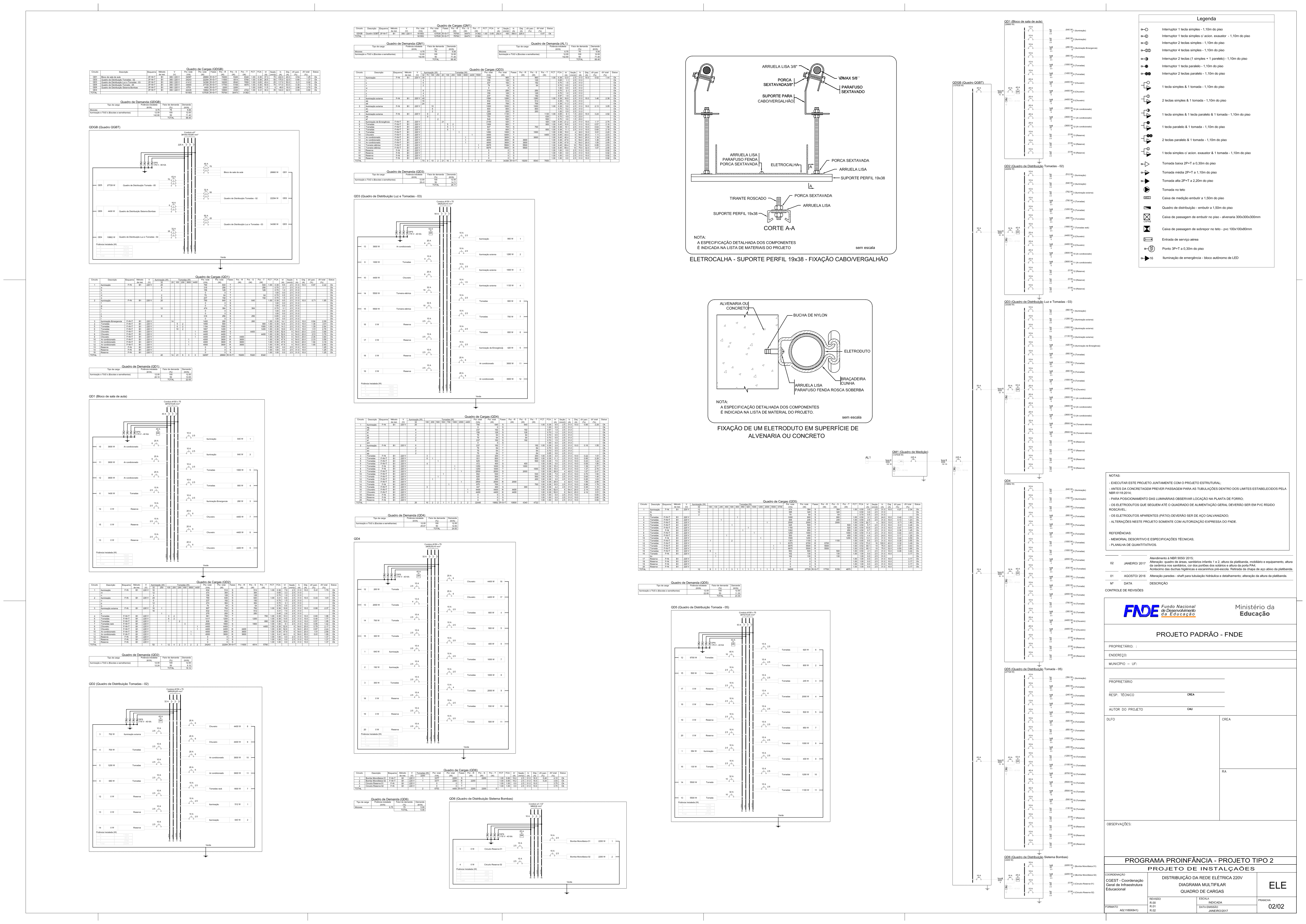
I'm an electrical engineer from Brazil and recently was tasked with performing a BOM for a children's school, as an OS enthusiast that had just found out about blender and bonsai I tried my best to fulfill the task with them. Maybe my noob choices and achievements help in some way to the discussion, so here it goes:
The modeling involved 3 main systems
1.1 Electrical
1.2 Advanced Technologies Networks
1.3 And Protection Against Lightning Discharges
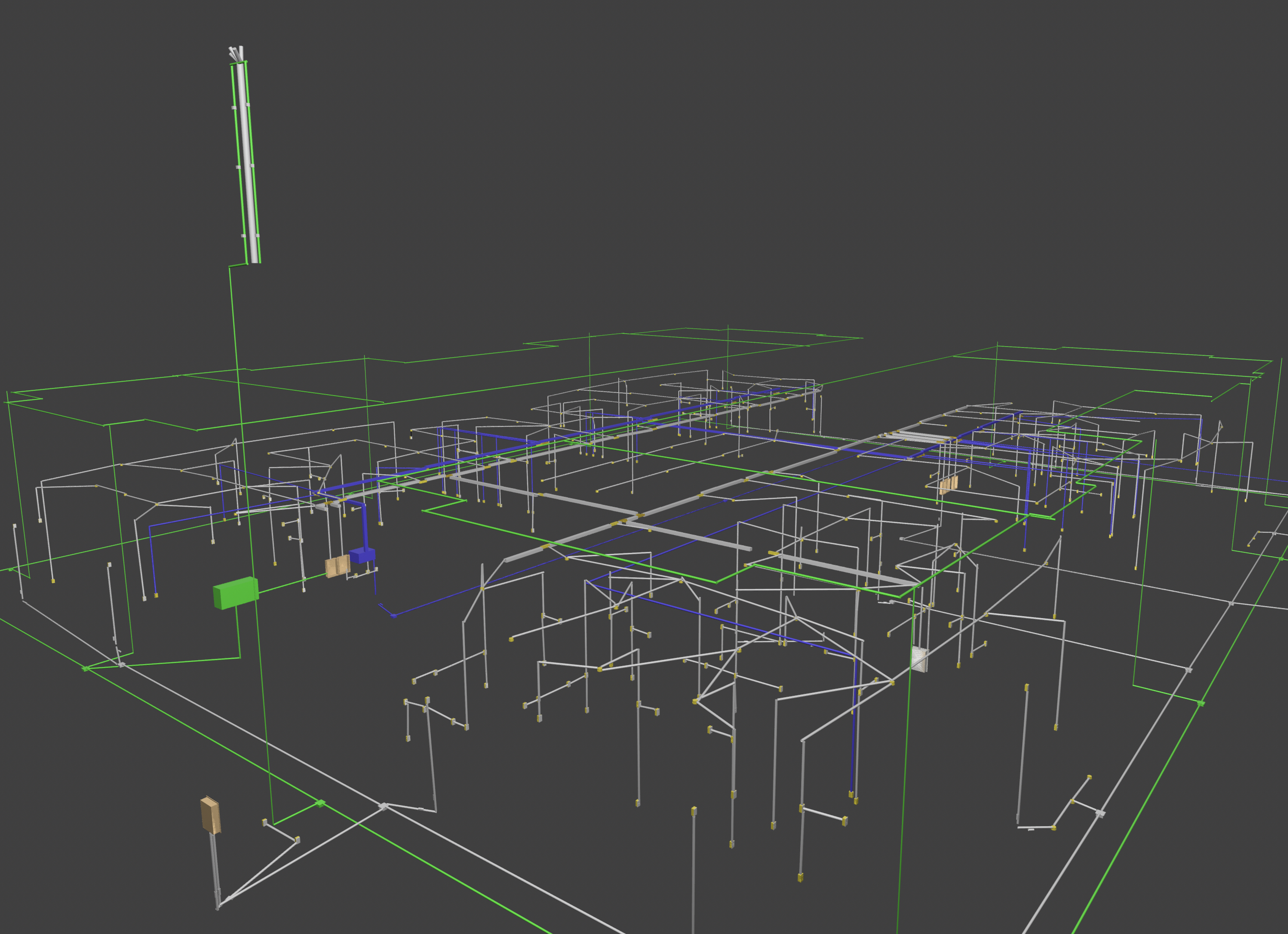
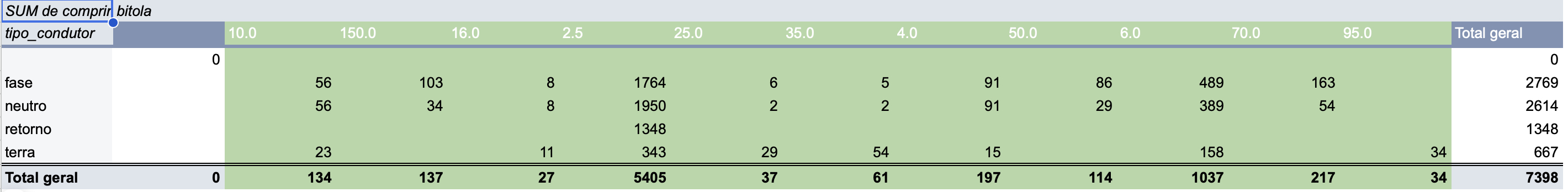
In the beginning my only goal was to find out the amount of cables of each color and thickness I would need in order to execute the installation, but soon enough many other questions followed. Basically (as I think @Lukas mentioned) managing collisions and integration between systems is a huge part of the day to day MEP design, but truth be told depending on the people, sometimes it gets overlooked and passes along to the construction team, when there is no BIM involved it gets exponentially more troublesome.
This is what I managed to model so far:
Some of the main problems I faced were due to lack of experience with the software and short deadline:
1 - I couldn't wrap my head around the segment polylines, It seemed that connecting two of them made me lose the Length, so I made two separate segments disconnected and had no respect for the alignment.
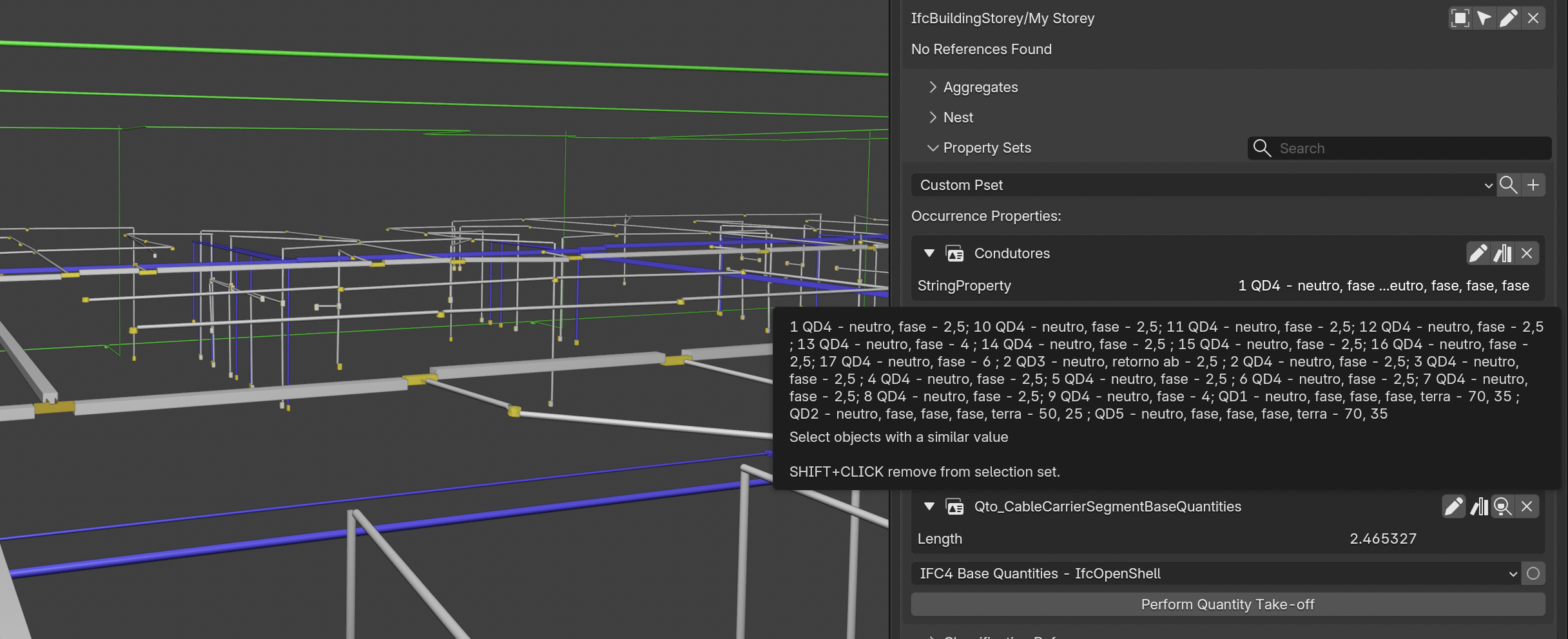
2 - Was not able to understand the PSets best suited to identifying phases, grounds, returns.. so I created one and painfully translated from the drawing one at a time what each carrier was (well..) carrying.
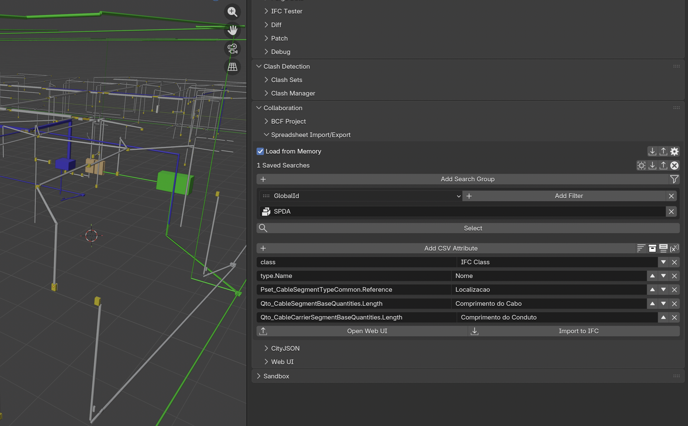
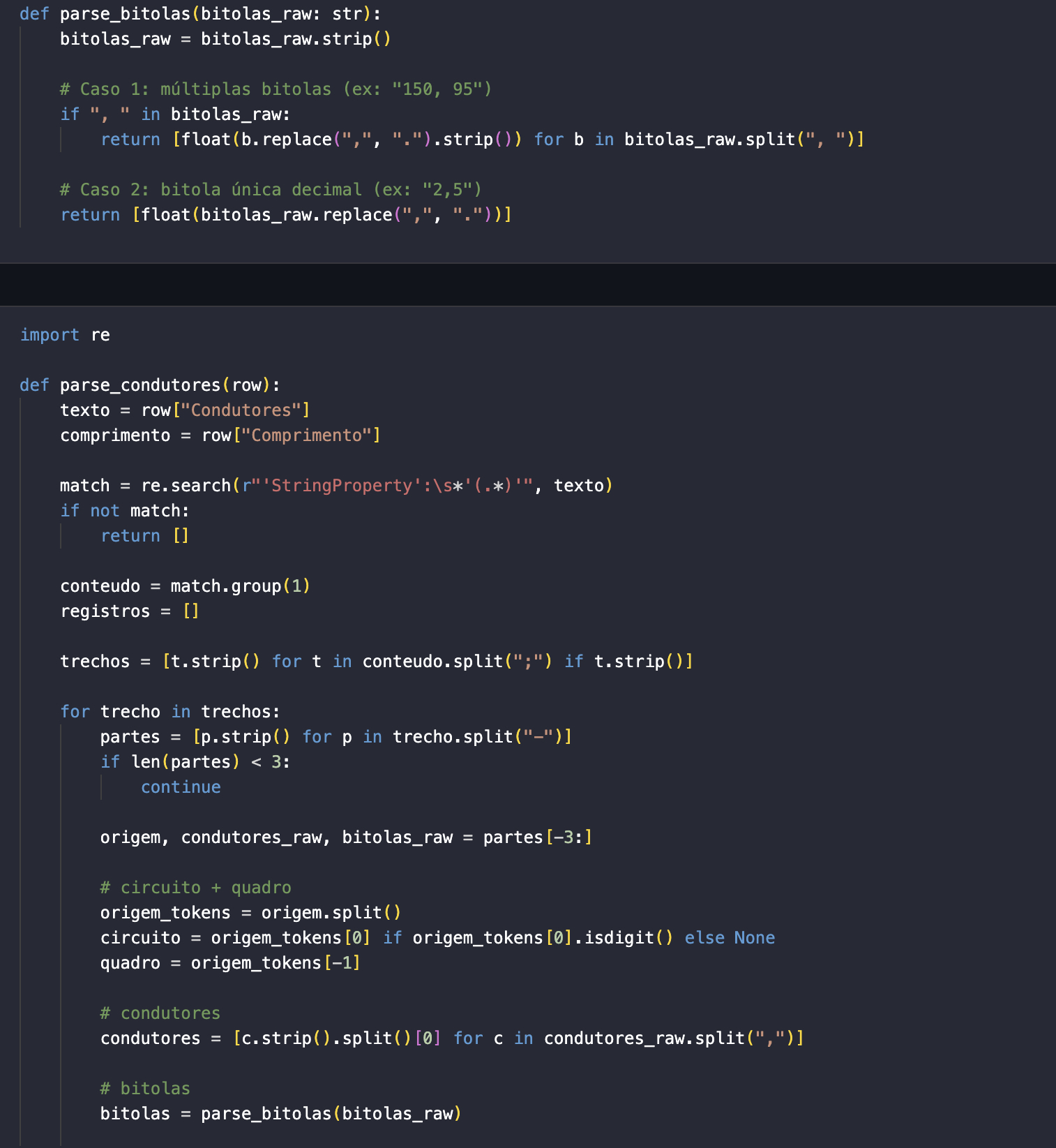
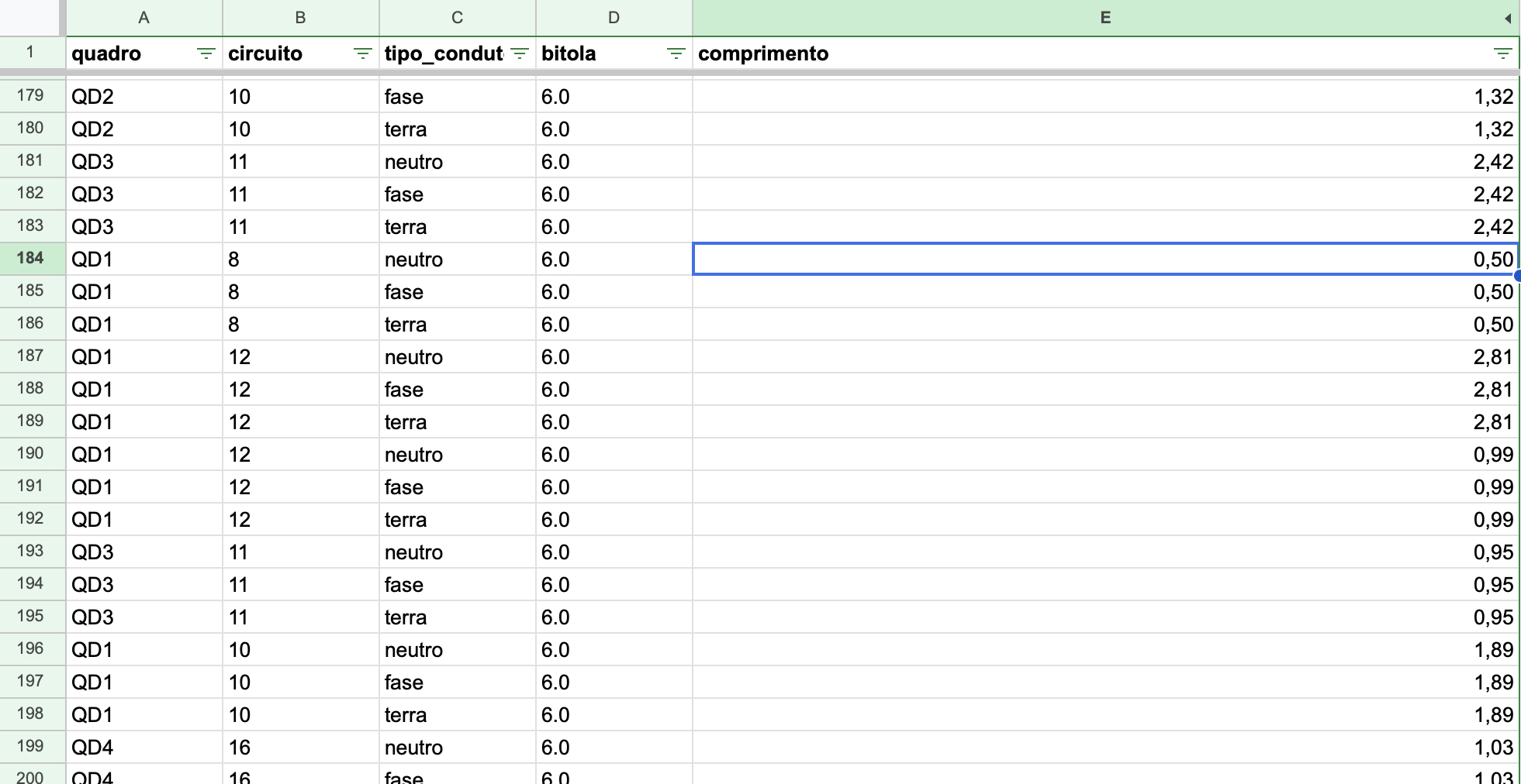
3 - Then I exported the IFC info as a CSV and used a bit of Pandas to extract the quantities I needed
I was sure that there was a better way to do that (at least I still hope there is)
Then I started playing with the systems tab and fell in here.
So main takeaways:
1 - I agree that we can use factors to approximate the curves in order to use straight segments instead, but isn't one of the beauties of BIM the ability to model real life things to be built? We have rigid conduits, but flexible ones are the most common, as well as cables doing turns as curves. I get the ports connections and the workaround with the curve-mesh-curve-mesh thing, but to large projects I can see people selling their organs in order to buy a better user experience in other solutions.
2 - The filling problem I did not face in this case, but I can see it happening a lot. Here in Brazil we have standard maximum filling percentages based on the method of installation, such as if it is a closed conduit inside a brick wall its considered B1 and so the maximum I can fill is 40% of the available area, but it can also changes based on the amount of circuits associated with the cables inside of that segment. In the future, being able to play with those many variables inside the systems would be amazing so we could generate truly accurate MEP tables with little effort after modeling.
3 - My child dream was having the same level of details softwares put into mechanical and civil engineering being presented in electrical solutions so we can have a little rest imagining and simplifying schemes and block diagrams.
4 - It seems MEP in Bonsai has come a long way and this thread shows how active and fantastic this community is. I'm really excited to what comes next and hope the upcoming updates features a huge groundbreaking tool.
@Hans said:
This can be achieved with Autodesk Inventor and schematics can be linked from Inventor to Eplan.
I never used Inventor, but to be honest I'm in no position to buy Autodesk solutions for a while haha and never heard of Eplan too, but in a quick search it seems to be the holy grail of electrical engineering. Sadly apart from being a paid solution, it's also only available for windows and I found myself being a Mac user this season.
But it gave me a feel ideas on how to further improve bonsai to electrical work.
I would say the improvements are related to 3 categories:
1 - Modeling visualization
It seems this has been greatly discussed here so far and the solutions presented I think are going to a great direction: space modeling with cables modeled inside conduit segments connected (nested maybe) so that one function could be aware of the total area of the conduit and the many cables inside it with their respective cross areas so it can be made a subtraction in order to establish the available area for new cables. (I think it seems like a smart IDS coming natively to bonsai in the future)
As @falken10vdl put it something like that would be the basis for connection:
The thing is that with MEP we always have to think from source to sink, so even agreeing that terminal circuits are the main source of pain in our day to day modeling lives, I think we would have to start from thinking about the delivery of energy into the facilities.
Let's say we have an electrical board ment to measurement, and we call it MED Board, from it we would have as many other distribution boards as needed in the building which could be called QD1, QD2, QD3 and so on. Each board would need to have an amount of poles to accommodate protection equipment and buses for deriving neutral and ground cables. The relationship among these boards we call electrical boards hierarchy.
I made this quick drawing to illustrate it but I might have missed something:
I don't know much about geo nodes, but something inside me tells me that it could somehow be used to build this parametrically and procedure wise.
I'd just ask to include the boards in it, so we could derive circuit based but also board based info from it.
I believe it is already possible somehow store and get those relations as of today in bonsai, maybe the great effort would be making it user friendly in the interface. The systems interface has a lot of potential but I believe it is still asking for some love.
What if we could include in this table input like fields so we can add info about the added elements that would be later attached as PSet info in the creation.
If this create cables button could be connected to paths (and paths could be used as native "profiles" for placing conduits and cables to allow curves) and IFC elements, imagine the beautiful magic of just setting it up, clicking the button and everything coming to life as a MEP system 3D modeled.
3 - Schematics and table summaries
Finally, it seems too much to ask, but basically we need to produce one-line diagrams and detailed sheets in our projects. I know 2D blocks are still something not properly included in the roadmap for bonsai to handle, but it makes me imagine that having all this info well organized might open space to not only export csv like sheets but also having them interactively included in the interface, much like what we can see beautifully today with Gantt charts.
Just as an example of what I'm talking about:
Version: 0.1 — February 2026 Context: Synthesized from the OSArch community threads on IfcDistributionSystem modeling, MEP Systems UI, and spatial containment of IfcDistributionElements.
Vision
Transform Bonsai into a first-class open-source environment for electrical BIM — from cable routing and quantity takeoff through standards compliance and single-line diagram generation — while remaining faithful to the IFC schema and interoperable with the broader open-source electrical toolchain (QElectroTech, FreeCAD Cables Workbench, pandapower/PyPSA).
Stakeholder Needs (from community feedback)
Persona
Core need
Key quotes / sources
Electrical designer (engcleberfeitosa, walpa)
Model cables with realistic geometry, assign to circuits, extract BOM
"managing collisions and integration between systems is a huge part of the day to day MEP design"
Quantity surveyor (lukas, Breogan10)
Cable lengths per type, fill ratios, circuit-level aggregates
"One need the total length of each cable(Type, Mounting)"
Standards engineer (lukas, Falkeng)
VDE/NEC/CENELEC compliance checks, fire rating, installation method
"german VDE rules the most restrictive in the world"
Coordination lead (Hans)
Spatial clash detection, carrier fill verification, audit via COBie
"mainly spatial coordination… IFC is totally auditable using COBie"
Software developer (falken10vdl, walpa)
Clean UI, port automation, extensible architecture
Detailed UI proposals and PRs (#7611, #7633)
Phase 0 — Foundations (Current → +2 months)
Goal: stabilize and polish what exists so every subsequent phase has solid ground.
0.1 Port & connectivity fixes
Auto-connect segments created by the polyline cable tool. (PR #7611 by falken10vdl — merge and stabilize.)
"Establish Path Direction" operator — given a starting port, traverse connected elements setting SINK/SOURCE automatically. (PR in progress.)
Ordered multi-select connection: Allow shift-selecting segments in sequence in the 3D viewport, then one-click connect them all with correct port flow. Requires solving Blender's unordered selected_objects — workaround via selection-order tracking (ref: blender.stackexchange.com/questions/253427).
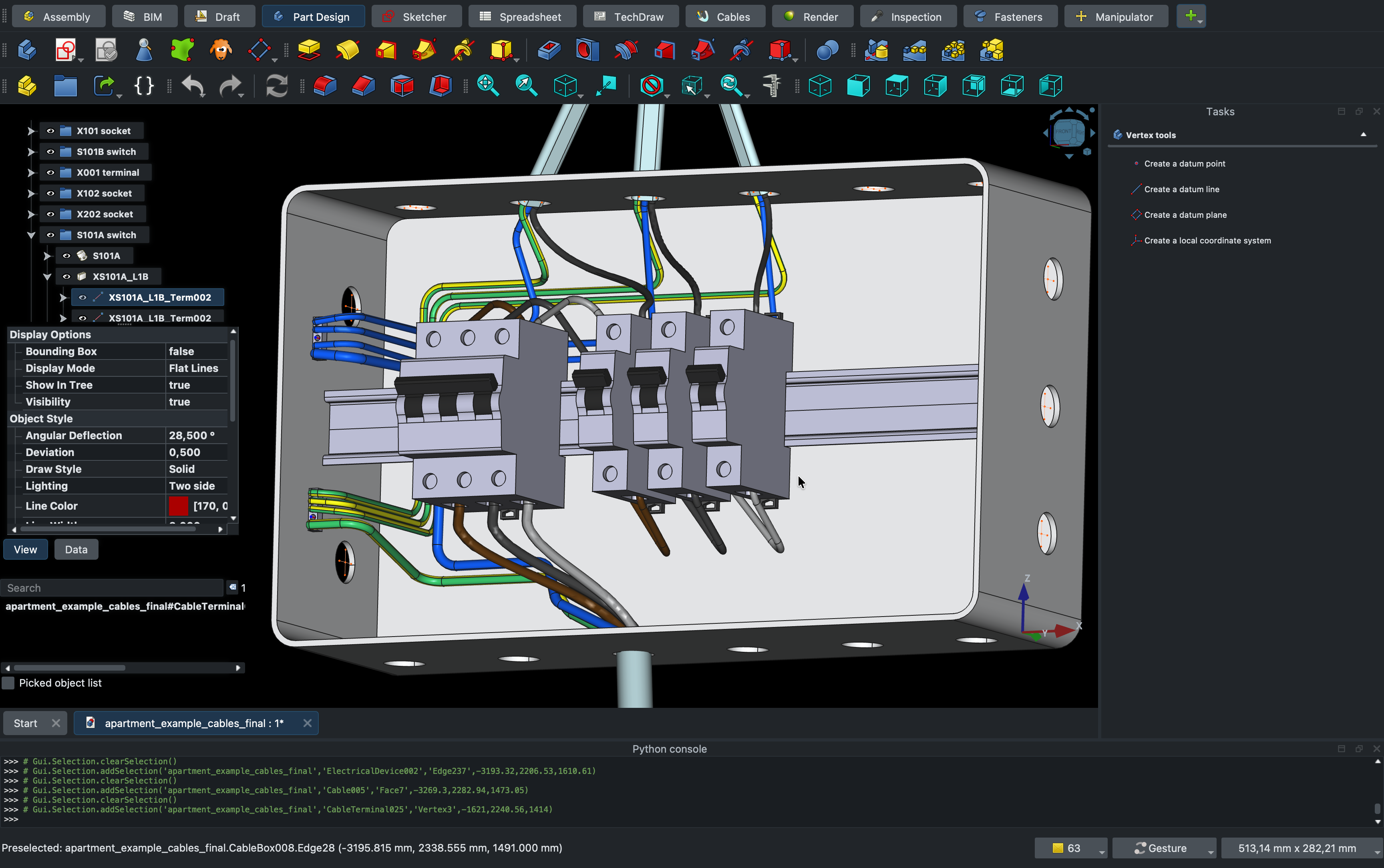
0.2 Cable modeling workflow
Document and streamline the curve → solid → mesh → IfcCableSegment path that steverugi demonstrated:
Create Bézier/NURBS curve
Set Data > Geometry > Bevel > Shape on 2D (or round profile)
Convert to mesh (Object → Convert → Mesh)
Assign IfcCableSegment via "Tessellation from Object"
Add a one-click "Cable from Curve" operator that automates steps 2-4 with a diameter parameter and optional IfcCableSegmentType assignment.
Ensure IfcCableSegmentType instances propagate length Qto (Qto_CableSegmentBaseQuantities.Length) — currently missing when cable is a mesh rather than extruded profile.
0.3 PSets for IfcDistributionCircuit / IfcDistributionSystem
Enable Pset editing on IfcDistributionCircuit and IfcDistributionSystem in the Object Information panel (currently missing — reported by Breogan10 and walpa).
Pre-populate Pset_DistributionSystemTypeElectrical fields when creating electrical systems.
0.4 Groups / System visibility
Show IfcDistributionSystem membership in the Object Information > Misc > Groups panel (partially working — falken10vdl noted "Electrical – MAIN" does not appear).
Add a "Spatial Container"-style line in Object Information showing which systems an element belongs to.
Goal: walpa's "dream interface" — define a circuit's endpoints and cable types, click "Create", and get routed cables with geometry.
3.1 Circuit path builder UI
Based on walpa's mockup:
Select circuit (IfcDistributionCircuit).
Define connection order — list of IfcDistributionElements with ports, ordered source → sink. Drag to reorder.
Select cable types — for each cable in the circuit (phase, neutral, ground), pick an IfcCableSegmentType from the cable palette.
"Create Cables" button — generates geometry along the path defined by port locations, assigns to circuit, creates IfcRelNests into carriers if a carrier path exists.
3.2 Path geometry engine
Generate cable geometry as IfcSweptDiskSolid (walpa's suggestion) or extruded IfcArbitraryClosedProfileDef along a guide curve.
Support fillets / chamfers at direction changes (minimum bend radius from cable type properties).
Editable after creation: tab into the cable to reposition control points, adjust cross-section, split into branches.
3.3 Cable carrier routing
Extend the existing Cable Carrier Tool to support:
Polyline paths that remain as a single IfcCableCarrierSegment (not split per edge).
Auto-generation of IfcCableCarrierFitting at direction changes.
Parametric cross-section (width × height or diameter) with fill-ratio live preview.
3.4 Automatic routing hints
Given a set of endpoints and a carrier network, suggest cable paths that minimize length while staying within carriers.
Stretch goal: respect zone rules (e.g., German installation zones in walls — lukas's feedback).
Goal: bridge the gap between 3D model and 2D electrical documentation.
5.1 Single-line diagram generation
From the IfcDistributionSystem graph, auto-generate a single-line diagram:
Board hierarchy as vertical tree.
Circuits as horizontal branches with breaker, cable designation, and load.
Standard symbols (IEC 60617 / ANSI).
Output as SVG (editable in Inkscape) or as a Bonsai 2D drawing sheet.
Driven by model data — changes to the system update the diagram.
5.2 QElectroTech integration
Import: parse QElectroTech .qet project files to extract circuit topology, component lists, and wire designations. Create corresponding IfcDistributionSystems and elements in Bonsai.
Export: generate .qet schematic from Bonsai's system graph for detailed schematic editing.
Bi-directional sync as a stretch goal (likely via an intermediate JSON/XML interchange format).
Phases 0-1 are prerequisites for everything. Phases 2-4 can partially overlap. Phase 5 depends on mature system/circuit data (Phases 1+4). Phase 6 can begin as soon as Phase 1 validation is in place and grows with each subsequent phase.
Summary
This roadmap moves from stabilizing existing tools (Phase 0) through UI redesign (Phase 1), carrier intelligence (Phase 2), smart routing (Phase 3), board modeling (Phase 4), documentation interop (Phase 5), and finally compliance automation (Phase 6). Each phase delivers standalone value while building toward the full vision of an open-source electrical BIM workspace that rivals — and in openness surpasses — proprietary alternatives.
The community contributors who shaped this roadmap (steverugi, walpa, falken10vdl, lukas, Falkeng, Hans, KoAra, Breogan10, engcleberfeitosa, Moult) represent exactly the collaborative energy needed to execute it. The next step is to prioritize within Phase 0 and begin.
Would this be an acceptable workflow?
Diagram (Qelt) --> Transform to 3D/BIM (FC) --> System/Qto/Psets/costs/planning (BB)
Cheers!
Fantastic! I used freeCad before but had no idea the cables workbench was so good. QElectroTech is also a great app, I wonder if in the future the point will be improving integration or importing those features directly into blender. Addons like CADSketcher, CAD Transform and Bonsai make me think a system unified approach would be the way to go. Things like importing errors or managing compatibility while different apps evolve concerns me a bit.
About the final result, even thought I can see the power related to the click and generate functionality, I wish there could be further level of editing. I tried to hide just the conduit but it's the same element in the cables approach, so it hides both the conduit and the wires coming out of it. In an IFC point of view it would be better to have the conduit generated with one profile and inside it the wires with a different and individual profile for each. It would later allow easier editing.
Same goes for the junction boxes where it seems that one conduit is always being generated for each group of cables, which normally is
not the case.
That being said, if those capabilities of entities connections with dedicated ports assigned freely in the 3D object, paths used for oriented automatic generation and derived table of info direct from the model such as shown in their integration, into bonsai. This would be a groundbreaking update in its MEP capabilities.
Most of it maybe is already done waiting to be arranged:
Ports holding connection information between elements - In need to be as many as wanted in the same object and freely placeable manner.
Nested objects can be use to derive hierarchy between elements - Maybe in need of a better UI to manage them
Bezier curve can already be transformed into a mesh and follow a profile - In need of a more efficient workflow to draw them, maybe something like a support line option directly in the IFC conduit and cables options, directly combined with a profile. Something like while adding a new cable type element being able to select both a profile and a segment type like a curved segment and at the end based on those automatically attach ports.
I agree with @Hans, going from 3D to diagram seems a better workflow.


Comments
Probably are the german VDE rules the most restrictiv in the world. Each cable has within its wires a green/yellow wire for 'ground' and a blue wire for 'neutral'. So your cables are named NYM-J-3x1,5 for single phase power distribution to a sink (light bulb f.i.) ( N = Normenleitung, Y = Isolierung der Adern aus Polyvinylchlorid (PVC), M = Mantelleitung, -J = mit grün-gelbem Schutzleiter, 3 = Anzahl der Adern, x = "mal"
1,5 = Leiterquerschnitt in mm2) (see https://de.wikipedia.org/wiki/Kennzeichnung_von_Leitungen_und_Kabeln)
When I say Cable , i mean a set of wires . The directionality is not required for any cable (but probably helps for some checking routines from the used software).
Then they are different levels of modeling.. in fact the 'electrical engineer' does not have to model each cable to each 'switch device' and 'sink' or 'plug'. He has to know which cable length of which cable type is needed for the installation and assign it to a distribution circuit number in order to make a good Quantity list which then will be 'priced' by the contractor. The contractor (electrical installation enterprise) will have to complete the 'engineers'-model with a detailed 'montage-plan' ('installation plan'). The contractor has some freedom to redefine the cable paths and even some conduits/carriers paths. But the engineers duty is to deliver a working (collision free) configuration for the whole electrical distribution system. So wall openings for carrier-systems are usually already defined in accordance with the architect, who has to coordinate the technical feasability of all systems in provenience of all the technical installations (heating, air, water, electricity (heavy duty/power), electricity (security, controlsystem,sound...))..you name it..
Here comes the Fill-Ratio for carrier-systems. They can hold only a limited amount of cables (because of weigth or just space).
The way DDS-CAD (now Graphisoft) use to handle those carrier-systems was to register each cable running in the carrier at each input/output port, and like this, knew its filling-ratio at each point in space. cable were not modeled as cylinder in the carrier, but only a squared volume representing the amount of cable (filling ratio).
Where can I see the IFC scheme for the electrical devices.. there are omniclass, etim.. and probably many more classification systems.. our library should try not to reinvent the wheel..
I downloaded a IFC4 piece of carrier from 3dfindit.com.. but windows was not able to extract the zip container as the filename was too long.. an example not to reproduce.
I'm having a hard time grasping the IfcSharedBldgServiceElements and IfcElectricalDomain in the IFC document.
How should Cable Segment, Cable Carrier Segment, Ports, and the system be related as IfcSharedBldgServiceElements?
Pset_DistributionSystemTypeElectrical provides items that could be useful for cable size calculations. bSI seems to consider electrical issues, but it's difficult.
@KoAra
you are not alone, while I have only gratitude for the team who put together the documentation, sometimes I silently cry when I try to decipher its content. But I was told it's a good brain exercise to fight Alzheimer, so I carry on.
The way I see it (a bit odd that such specific topic takes most of the description of a generic entity like IfcDistributionSystem) given its nature a carrier may be set as 'agnostic' as to being able to host different predefined types.
To me a distribution port is just a connector that can play in different environments but carries out the same role, making elements of a discipline (as nicely illustrated in the IfcSharedBldgServiceElements page) talk to each other. Is there something of the pipe example that you find difficult ?
That one is particularly insidious, my best shot: it's an example of how an external system 1 interconnects using an IfcAssignToProduct via a port part of system 2. Whereas systems and nested systems use IfcAssignsToGroup relationship instead.
I don't understand the question, if you could please give a practical example
yes, thanks
I am not familiar with this, maybe others?
I can see this system topic gained some attention, good! I hope others will jump in to give all of us more insights.
cheers and happy MEP modeling
@KoAra
I fully agree with @steverugi, we're all in the same boat....
Consider the IfcDistributionSystem as groups of objects (a main group can contain multiple branch groups) and their objects are connected through ports.
I think (but I could be wrong) that ifcSharedBldgServiceElements is just a conceptual layer in the ifc schema that groups concepts linked to the MEP domain; it's not an element that is "modeled". Just like ifcSharedBldgElements is a layer where you group the common elements of a civil construction.
cheers
I couldn't find any IfcRelationship in the IFC documentation that identifies the cables associated with a cable carrier.
This relationship would be useful for the automated calculation/verification of the fill ratio established in the standards.
Perhaps IfcRelInterferesElements? But I think it's specific to clash detection.
Does anyone have any knowledge of this?
Is there another way, without the need for a relationship?
Thanks
@lukas Vielen Dank! Ich habe einmal in der Schweiz gearbeitet und kann ein bisschen Deutsch :)
That is a very good insight in how to model all this. I can follow the naming and coloring you were explaining as I believe a lot of DIN/VDE is in the CEE and CENELEC so many countries in Europe have a similar setting.
Regarding fill ratio, what would be your recommendation to be as IFC as much compliant? I have seen that Qto_PipeSegmentBaseQuantities provides GrossCrossSectionArea & NetCrossSectionArea since pipes are completely enclosed. However for the case of Qto_CableCarrierSegmentBaseQuantities there is only CrossSectionArea since cablecarriers can also be open. So we do not have a value for the available net space for cables. In IFC4 there is for CABLETRUNKINGSEGMENT Pset_CableCarrierSegmentTypeCableTrunkingSegment with NominalWidth & NominalHeight but that has been removed in IFC4X3 so not a reliable source.
One possibility would then be to compute knowing the type of profile (Typically IfcRectangleHollowProfileDef or IfcCircleHollowProfileDef) the actual net cross section... Any other ideas?
Thanks!
PS: Do you know the difference between CORESEGMENT and CONDUCTORSEGMENT? Core=conductor+its insulation?
Do you know how is the physical containment done in Bonsai? I mean I have a IfcCableCarrierSegment (from its corresponding predefined type CABLETRUNKINGSEGMENT) for the cable tray (enclosed). Within that tray a I have a number of conduits which are also IfcCableCarrierSegment but predefined type CONDUITSEGMENT. Finally there are a number of IfcCableSegments (of predefined type CABLESEGMENT, CORESEGMENT, etc.).
In order to know fill ratios we must have physical containement established between them. How is this done in Bonsai?
Thanks!
@walpa I believe this concept is awesome! Let me try to do something around it. To me the idea of making a MEP path builder to explicitly show the IfcDistribution components in order of connection (and down below the ports) is a really nice approach. In the end, these "pipes" start from a relevant port and continue adding untill you end up in a final one. All the intermediate beign segments or fittings which basically need to allign with the z axis of the path... Thanks!
ping @velochad @jsbanky @mgateno @Nc42 @Arthur @thorwood @Hans @Zecruel @jvitor23 @s6k
:)
I have tried with Nests in Bonsai. I guess it is a valid possibility?

Cheers!
IfcRelNests documentation:
"Decompositions imply a dependency, i.e. the definition of the whole depends on the definition of the parts and the parts depend on the existence of the whole. The behaviour that is implied from the dependency has to be established inside the applications."
This sentence confused me. Does this dependence exist or not in the case of cables and cable carriers?
I have just seen that Nests allow me to establish a hierarchy of spatial containment... But I do not knwo if there are other ways...
The idea behind is to be able to know fill ratio and check that the paths are correctly made of the corresponding amount of segments+fittings...
@sjb007 Since you have modeled cable trays (saw your comment to https://github.com/IfcOpenShell/IfcOpenShell/issues/7618). What is your experience between IfcCableCarrierSegment and IfcCableSegment? Do you establish any relationship between them to have an idea of fill ratio?
I guess that ideally a sort of IfcRel... type of binding would be best, but I guess that otherwise some PSet with naming relations coould be another option?
Cheers!
@falken10vdl Wooooooahhh there!!!! I think you are confusing me with someone else! :-D The cable trays (more accurately wire mesh cable trays) I'm talking about seeing were about 30 years ago. I sure as heck didn't model them. All I did was lay cable in them as a junior IT guy. Now I'm just a much older nerdy IT guy who got interested in Bonsai for personal reasons. I have no construction industry experience here. Around these parts I like to follow to the old adage "Better to remain silent and be thought a fool than to open one's mouth and put it beyond doubt."
IFC separates segments and fittings, which makes sense from a product calculation perspective, but it's cumbersome from the standpoint of the port connect system and modeling rearizing elements. Electrical designers must handle both cable segments and cable carrier segments.CONDUIT.
I look forward to your development.
I am sorry but I can not help on any IFC definition or howto.. even if I follow osarch.org for quite long now. never put my hands on.. do not know how 'nested' is then counted for the length of the cable.. in fact, modeling each cable is an overkill.. so they can be needed as IFC , logically in the background to have a BOM, and to know if carriers/conduits still have capacity. The bigger cable (from power delivery starting from ~10 kW) could be modeled. These are also the more expensive ones. The smaller cables can just be counted from the amount of switches, plugs and luminaries installed, with an average length depending on the room distance to the electric-distribution-board.
In Germany, even this amount of switches and plugs in defined in some VDE rules, their z-position in/on the wall too.
The (small) cables run either on the floor (under the 'estrich' - floor screed?) or within the concrete ceiling. In that case a conduit plan is needed for those ceilings. For the cables running on the floor or in the walls , zones are defined for them to be installed.
I was hoping that with the use of those rules (which can be set with bsdd? or ids? or ontology based plugin like topologic) some rough automation is feasable. Like: light source in the middle of the ceiling, switch at the entrance door (two-way if 2 doors), plugs in the corner or beyond windows etc...
In fact, german electroplaning is a task for a dedicated AI. Probably it will not take long anymore.
@falken10vdl
How are you planning to implement this?
An automatic check at the time of nesting (if that's the correct relationship) of the cable to the carrier?
Since the fill ratio can vary greatly (different standards for each situation), IMO the ideal is to store this value in a pset.
I didn't find a specific field for this in the documentation, so I suggest:
Pset_Tolerance.OverallTolerance * Qto_CableCarrierSegmentBaseQuantities.CrossSectionArea
For the area to be compared with the sum of the cable cross section areas.
What do the expert friends think about this?
Here is a first proposal to address the visualization of MEP systems based on @walpa 's idea commented in this thread above.
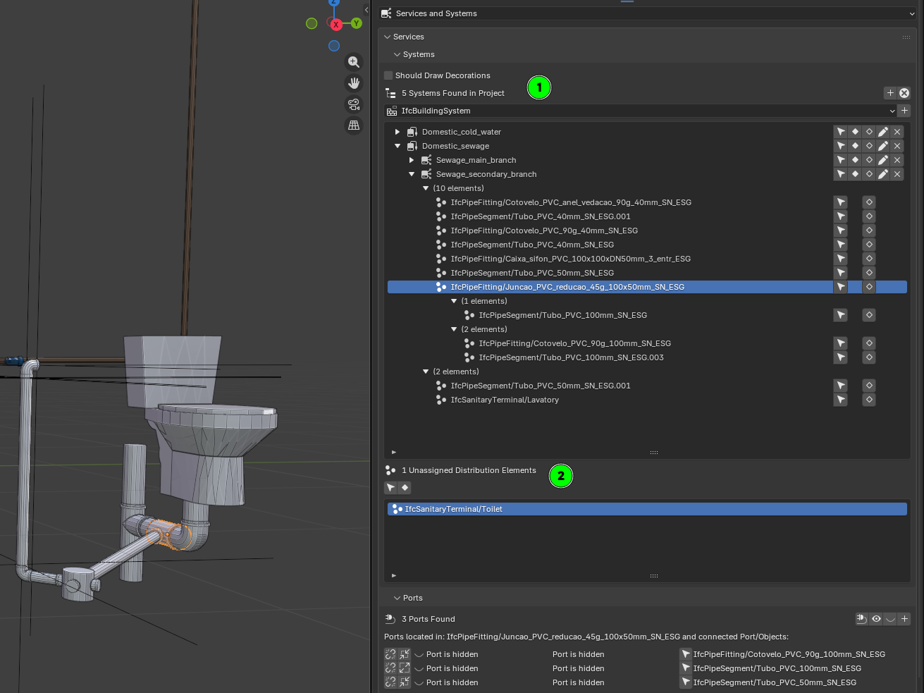
The PR MEP-system-building-enhancements #7633 tries to address that.
Mainly there are two improvements:
1. The UIList for the systems now also has the elements connected to the system. Moreover I have tried to order the elements there in branches of elements connected between them. Please note that from what I have seen in Ifc documentation, there could be cycles so it is not an easy task. Currently the logic tries to identify an element connected to another out of that system connected as a sink port and then try to build the chain from there. If it find the element it already parse it stops.
2. Added another UIList with the Distribution elements not assigned to any system (please note that the same element can be assigned to multiple systems, so only if you remove them form all they will appear here)
I do not know if this "automated" approach is best or we should go for the user to establish the order of connection explicitly (or at least the head of the chain)
Your feedback is very welcome.
Thanks!
I loved the ability to see the objects that are grouped in the system and those that are not grouped, without having to resort to the group UI.
I think that for this UI, showing the order of the connected elements is very interesting, but perhaps it's overkill. In very complex systems this can become confusing.
Anyway, thank you once again for your dedication.
The PR can be tested in latest bonsaiPR BonsaiPR v0.8.5-alpha260202-1d06dbb
Cheers!
This thread has been one of the best readings I had in a long time. I wish I got to it a few weeks ago haha
I'm an electrical engineer from Brazil and recently was tasked with performing a BOM for a children's school, as an OS enthusiast that had just found out about blender and bonsai I tried my best to fulfill the task with them. Maybe my noob choices and achievements help in some way to the discussion, so here it goes:
1.1 Electrical
1.2 Advanced Technologies Networks
1.3 And Protection Against Lightning Discharges
In the beginning my only goal was to find out the amount of cables of each color and thickness I would need in order to execute the installation, but soon enough many other questions followed. Basically (as I think @Lukas mentioned) managing collisions and integration between systems is a huge part of the day to day MEP design, but truth be told depending on the people, sometimes it gets overlooked and passes along to the construction team, when there is no BIM involved it gets exponentially more troublesome.
This is what I managed to model so far:
Some of the main problems I faced were due to lack of experience with the software and short deadline:
1 - I couldn't wrap my head around the segment polylines, It seemed that connecting two of them made me lose the Length, so I made two separate segments disconnected and had no respect for the alignment.
2 - Was not able to understand the PSets best suited to identifying phases, grounds, returns.. so I created one and painfully translated from the drawing one at a time what each carrier was (well..) carrying.
3 - Then I exported the IFC info as a CSV and used a bit of Pandas to extract the quantities I needed
I was sure that there was a better way to do that (at least I still hope there is)
Then I started playing with the systems tab and fell in here.
So main takeaways:
1 - I agree that we can use factors to approximate the curves in order to use straight segments instead, but isn't one of the beauties of BIM the ability to model real life things to be built? We have rigid conduits, but flexible ones are the most common, as well as cables doing turns as curves. I get the ports connections and the workaround with the curve-mesh-curve-mesh thing, but to large projects I can see people selling their organs in order to buy a better user experience in other solutions.
2 - The filling problem I did not face in this case, but I can see it happening a lot. Here in Brazil we have standard maximum filling percentages based on the method of installation, such as if it is a closed conduit inside a brick wall its considered B1 and so the maximum I can fill is 40% of the available area, but it can also changes based on the amount of circuits associated with the cables inside of that segment. In the future, being able to play with those many variables inside the systems would be amazing so we could generate truly accurate MEP tables with little effort after modeling.
3 - My child dream was having the same level of details softwares put into mechanical and civil engineering being presented in electrical solutions so we can have a little rest imagining and simplifying schemes and block diagrams.
4 - It seems MEP in Bonsai has come a long way and this thread shows how active and fantastic this community is. I'm really excited to what comes next and hope the upcoming updates features a huge groundbreaking tool.
I never used Inventor, but to be honest I'm in no position to buy Autodesk solutions for a while haha and never heard of Eplan too, but in a quick search it seems to be the holy grail of electrical engineering. Sadly apart from being a paid solution, it's also only available for windows and I found myself being a Mac user this season.
But it gave me a feel ideas on how to further improve bonsai to electrical work.
I would say the improvements are related to 3 categories:
1 - Modeling visualization
It seems this has been greatly discussed here so far and the solutions presented I think are going to a great direction: space modeling with cables modeled inside conduit segments connected (nested maybe) so that one function could be aware of the total area of the conduit and the many cables inside it with their respective cross areas so it can be made a subtraction in order to establish the available area for new cables. (I think it seems like a smart IDS coming natively to bonsai in the future)
As @falken10vdl put it something like that would be the basis for connection:
The thing is that with MEP we always have to think from source to sink, so even agreeing that terminal circuits are the main source of pain in our day to day modeling lives, I think we would have to start from thinking about the delivery of energy into the facilities.
Let's say we have an electrical board ment to measurement, and we call it MED Board, from it we would have as many other distribution boards as needed in the building which could be called QD1, QD2, QD3 and so on. Each board would need to have an amount of poles to accommodate protection equipment and buses for deriving neutral and ground cables. The relationship among these boards we call electrical boards hierarchy.
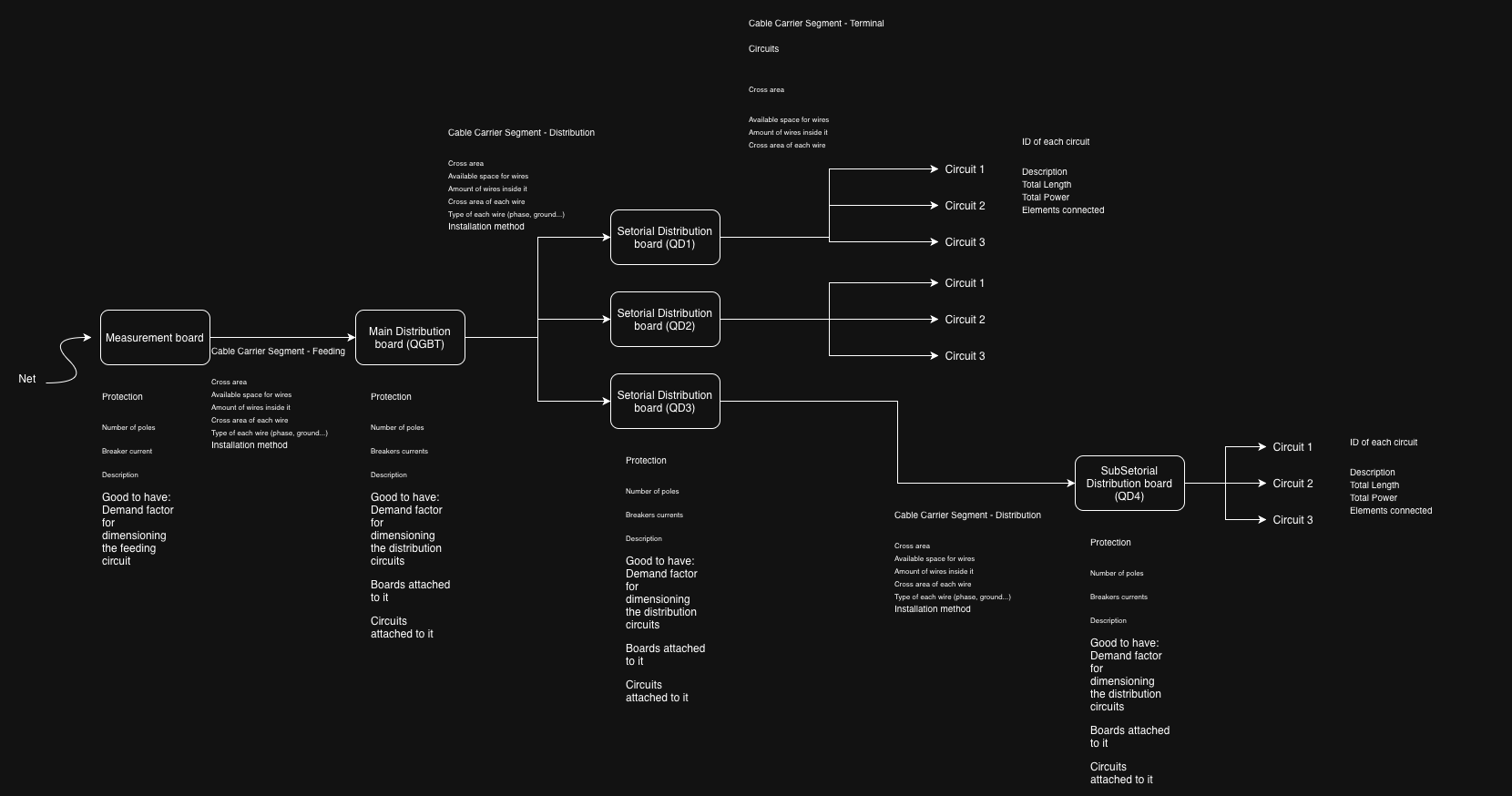
I made this quick drawing to illustrate it but I might have missed something:
I don't know much about geo nodes, but something inside me tells me that it could somehow be used to build this parametrically and procedure wise.
2 - Information management
I share @walpa dream for this interface
I'd just ask to include the boards in it, so we could derive circuit based but also board based info from it.
I believe it is already possible somehow store and get those relations as of today in bonsai, maybe the great effort would be making it user friendly in the interface. The systems interface has a lot of potential but I believe it is still asking for some love.
What if we could include in this table input like fields so we can add info about the added elements that would be later attached as PSet info in the creation.
If this create cables button could be connected to paths (and paths could be used as native "profiles" for placing conduits and cables to allow curves) and IFC elements, imagine the beautiful magic of just setting it up, clicking the button and everything coming to life as a MEP system 3D modeled.
3 - Schematics and table summaries
Finally, it seems too much to ask, but basically we need to produce one-line diagrams and detailed sheets in our projects. I know 2D blocks are still something not properly included in the roadmap for bonsai to handle, but it makes me imagine that having all this info well organized might open space to not only export csv like sheets but also having them interactively included in the interface, much like what we can see beautifully today with Gantt charts.
Just as an example of what I'm talking about:
Schemdraw for future thoughts and inspiration for electrical wiring diagrams.
watch this !
https://qelectrotech.org/forum/search.php?search_id=126623035
you are not alone..
Digging deeper:
Cables Workbench in FreeCAD: https://wiki.freecad.org/Cables_Workbench
QElectroTech integration with FreeCAD: https://qelectrotech.org/forum/viewtopic.php?id=3093
Would this be an acceptable workflow?
Diagram (Qelt) --> Transform to 3D/BIM (FC) --> System/Qto/Psets/costs/planning (BB)
Cheers!
That is very interesting! QElectroTech looks very nice!
I have no idea what's going on here, but i like it! Here's an AI assessment, if interested...helps me understand.
Electrical Workspace Roadmap — Bonsai / IfcOpenShell
Version: 0.1 — February 2026 Context: Synthesized from the OSArch community threads on IfcDistributionSystem modeling, MEP Systems UI, and spatial containment of IfcDistributionElements.
Vision
Transform Bonsai into a first-class open-source environment for electrical BIM — from cable routing and quantity takeoff through standards compliance and single-line diagram generation — while remaining faithful to the IFC schema and interoperable with the broader open-source electrical toolchain (QElectroTech, FreeCAD Cables Workbench, pandapower/PyPSA).
Stakeholder Needs (from community feedback)
Phase 0 — Foundations (Current → +2 months)
Goal: stabilize and polish what exists so every subsequent phase has solid ground.
0.1 Port & connectivity fixes
selected_objects— workaround via selection-order tracking (ref: blender.stackexchange.com/questions/253427).0.2 Cable modeling workflow
Document and streamline the curve → solid → mesh → IfcCableSegment path that steverugi demonstrated:
Add a one-click "Cable from Curve" operator that automates steps 2-4 with a diameter parameter and optional IfcCableSegmentType assignment.
Qto_CableSegmentBaseQuantities.Length) — currently missing when cable is a mesh rather than extruded profile.0.3 PSets for IfcDistributionCircuit / IfcDistributionSystem
Pset_DistributionSystemTypeElectricalfields when creating electrical systems.0.4 Groups / System visibility
Phase 1 — MEP Systems UI Overhaul (+2 → +5 months)
Goal: a dedicated, responsive panel for building, inspecting, and validating distribution systems.
1.1 Systems panel (UIList 1)
1.2 System elements panel (UIList 2)
Multiple display modes (following the Spatial Decomposition UI pattern per walpa's proposal):
(unconnected / cross-system / total).1.3 Unassigned elements panel (UIList 3)
1.4 Ports panel (UIList 4)
1.5 System-level operators
Phase 2 — Cable & Carrier Intelligence (+5 → +8 months)
Goal: make cable-in-carrier relationships queryable and fill ratios calculable.
2.1 Physical containment via IfcRelNests
2.2 Fill ratio calculation
For each IfcCableCarrierSegment, compute:
Tolerance factor stored in
Pset_Tolerance.OverallTolerance(walpa's suggestion) or a customPset_CableCarrierFillRatio.2.3 Cable type & designation management
Support multi-core cable designation (e.g., NYM-J-3×1.5) with structured Pset fields:
Map to
Pset_CableSegmentTypeCableSegmentand extend with user-defined Psets where IFC is insufficient.2.4 Conduit ↔ cable association
Phase 3 — Smart Routing & Path Builder (+8 → +12 months)
Goal: walpa's "dream interface" — define a circuit's endpoints and cable types, click "Create", and get routed cables with geometry.
3.1 Circuit path builder UI
Based on walpa's mockup:
3.2 Path geometry engine
3.3 Cable carrier routing
3.4 Automatic routing hints
Phase 4 — Electrical Distribution Board Modeling (+10 → +14 months)
Goal: model the panel/board hierarchy that is central to every electrical project (engcleberfeitosa's request).
4.1 Board hierarchy
IfcElectricDistributionBoard as a first-class entity with:
Hierarchy: Metering board (MED) → sub-distribution boards (QD1, QD2…) via IfcRelAggregates.
4.2 Load calculation support
Pset_ElectricDistributionBoardTypeCommonor custom Psets.4.3 Cable sizing hints
Phase 5 — Schematics, Diagrams & Interoperability (+12 → +18 months)
Goal: bridge the gap between 3D model and 2D electrical documentation.
5.1 Single-line diagram generation
From the IfcDistributionSystem graph, auto-generate a single-line diagram:
Output as SVG (editable in Inkscape) or as a Bonsai 2D drawing sheet.
5.2 QElectroTech integration
.qetproject files to extract circuit topology, component lists, and wire designations. Create corresponding IfcDistributionSystems and elements in Bonsai..qetschematic from Bonsai's system graph for detailed schematic editing.5.3 FreeCAD Cables Workbench bridge
5.4 Spreadsheet / BOM export
.xlsxwith formatting, or as IFC cost schedule (IfcCostSchedule → IfcCostItem).Phase 6 — Validation, Compliance & Audit (+16 → +22 months)
Goal: make the electrical model auditable and standards-aware.
6.1 Rule engine integration
Define electrical rules as IDS (Information Delivery Specification) or via bSDD classifications:
Run validation: highlight non-compliant elements in 3D and in the Systems panel "Problem detected" mode.
6.2 COBie / audit export
6.3 Fire rating & acoustic checks
Cross-Cutting Concerns
Performance
IFC Schema Fidelity
Pset_CableCarrierSegmentTypeCableTrunkingSegmentNominalWidth/Height removed in IFC4X3).Relationship model summary
IfcRelAssignsToGroupIfcRelAggregatesIfcRelNestsIfcRelConnectsPortsIfcRelContainedInSpatialStructureIfcRelReferencedInSpatialStructureIfcRelAssignsToGroupDocumentation & onboarding
.ifcfiles (building on steverugi's examples), and short video tutorials.Dependency & Priority Map
Phases 0-1 are prerequisites for everything. Phases 2-4 can partially overlap. Phase 5 depends on mature system/circuit data (Phases 1+4). Phase 6 can begin as soon as Phase 1 validation is in place and grows with each subsequent phase.
Summary
This roadmap moves from stabilizing existing tools (Phase 0) through UI redesign (Phase 1), carrier intelligence (Phase 2), smart routing (Phase 3), board modeling (Phase 4), documentation interop (Phase 5), and finally compliance automation (Phase 6). Each phase delivers standalone value while building toward the full vision of an open-source electrical BIM workspace that rivals — and in openness surpasses — proprietary alternatives.
The community contributors who shaped this roadmap (steverugi, walpa, falken10vdl, lukas, Falkeng, Hans, KoAra, Breogan10, engcleberfeitosa, Moult) represent exactly the collaborative energy needed to execute it. The next step is to prioritize within Phase 0 and begin.
Fantastic! I used freeCad before but had no idea the cables workbench was so good. QElectroTech is also a great app, I wonder if in the future the point will be improving integration or importing those features directly into blender. Addons like CADSketcher, CAD Transform and Bonsai make me think a system unified approach would be the way to go. Things like importing errors or managing compatibility while different apps evolve concerns me a bit.
About the final result, even thought I can see the power related to the click and generate functionality, I wish there could be further level of editing. I tried to hide just the conduit but it's the same element in the cables approach, so it hides both the conduit and the wires coming out of it. In an IFC point of view it would be better to have the conduit generated with one profile and inside it the wires with a different and individual profile for each. It would later allow easier editing.
Same goes for the junction boxes where it seems that one conduit is always being generated for each group of cables, which normally is
not the case.
That being said, if those capabilities of entities connections with dedicated ports assigned freely in the 3D object, paths used for oriented automatic generation and derived table of info direct from the model such as shown in their integration, into bonsai. This would be a groundbreaking update in its MEP capabilities.
Most of it maybe is already done waiting to be arranged:
Ports holding connection information between elements - In need to be as many as wanted in the same object and freely placeable manner.
Nested objects can be use to derive hierarchy between elements - Maybe in need of a better UI to manage them
Bezier curve can already be transformed into a mesh and follow a profile - In need of a more efficient workflow to draw them, maybe something like a support line option directly in the IFC conduit and cables options, directly combined with a profile. Something like while adding a new cable type element being able to select both a profile and a segment type like a curved segment and at the end based on those automatically attach ports.
I agree with @Hans, going from 3D to diagram seems a better workflow.
Pics for easy access:
One thing though i do know, however, if an entire building was modeled to this level of detail, Blender would combust in flames.