@theoryshaw said:
One thing though i do know, however, if an entire building was modeled to this level of detail, Blender would combust in flames.
Where is your faith man? A few years ago the same could be said about multilayered walls or accurate textures in complex facades. Let's freely dream and hope for the efficiency wizards to perform their craft. I'm a bit traumatized by that cause people normally say it is not needed for electrical modeling because it's hidden inside the walls, it aways frustrates me a bit. The point is precisely achieving the superpower of being able to see through the walls at any time.
But seriously though, would it be gorgeous for the 5 seconds it would last before combusting?
Passing by to better illustrate to our fellow developers my child dream on electrical projects.
I'm now modeling a house for a friend and once again I wish I could do everything in blender beautifully as my heart desires.
He made the architectural design in Revit and exported the IFC to me. He is like me also autistic so he modeled in a way so that every ecobrick has its own geometry hahaha and well, It's gorgeous.
So I started designing the electrical systems within and for some reason my bonsai is really lagging on every insert of a new element :`(
(I know Mac is not the best to model, but I have a M3 Pro chip, and everything else goes rather fast)
I'd say pain by pain it is advancing
The thing is, I can't make amends in my mind with the impossibility of modeling the entire electrical system inside blender, just makes so much sense that I should be able to do it easily. So I tried with a lot of love and anxiety. This is what I managed to do so far:
I just modeled the main electrical boards, electrical points such as outlets and light fixtures.
Main annoying things so far:
Being unable to change the view angles while placing elements hurts and ends up demanding a lot more clicks than it could. I wish something like what the CAD Transform add-on allows: visibility free to move while modeling;
I still can't find a good way to connect conduits better than drawing from the junction box to a ceiling reference such as a light fixture, and after that from the end of the conduit to the final destination. If I could make a turn like in a Bézier curve it would be great. Sadly as profiles don't seem to allow this, and I particularly don't find useful the fitting and curves in light weight conduits, they keep on not well aligned;
Blender crashed a lot of times, mostly when I tried to import IfcProducts from previous projects or downloaded online. For some reason it would crash, forget the reference to the new inserted elements but keep their unlinked geometry in the viewport. It felt like death every time;
And what keeps me awake at night: how can I derive the cables quantities later on?
So I make a test in a way smaller scale to show how amazing electrical design can become if made a little bit less time consuming in the future:
Imagine an electrical engineer discussing with clients of fellow engineers and trying to explain why it's needed 5km of cables in a small building, and the sadness that comes when no one else can see the need for that many cables from your flat pdf drawing and not even from in the BIM modeling hidden in layers of info inside empty walls and emptier still conduits. Well, cry no more, what if there was a tool bringing light to it all?
A truly detailed board so the execution and client can read it without the need for a single-line diagram translation.
Than an X-Ray to see what hides beneath the bricks
And the angels of my dreams in all its glory inside the conduits showing where each cables starts and ends, no space to mistakes, true amount of cables inside to verify occupancy rates, accurate BOM for cables, beautiful as everything else. Please haha
For this I used some geometry nodes for the wires and the extra curves addons to extrude bezier and polys. It's still really time consuming.. the cables are not converted in IFC elements and because of that I did not use the systems to isolate the circuits, nor I can derive the lengths (I think). But if it serves as inspiration to someone in order to perfect a more efficient workflow in this regard, I could see all of our kind invading blender for good.
I'll leave here the blend and ifc (change of plans hahahah seems like some instance was lost and I can't export the ifc) files for the demo.
But here goes the .blend: GDrive
There's not many BIM modeling programs in the world, that could handle this level of detail for an entire house. :)
I know it's painful to compromise, but would suggest abstracting your geometry down to simple prismatic diagrams.
In my mind, when trying to determine how detailed something needs to be, I ask, "does the contractor really need this level of detail, to understand the design intent"?
Blender crashed a lot of times, mostly when I tried to import IfcProducts from previous projects or downloaded online.
@theoryshaw said:
One thing though i do know, however, if an entire building was modeled to this level of detail, Blender would combust in flames.
Currently what is the best workflow available in blender and bonsai, I mean to calculate the electrical wire need according to the thickness of each, how should we proceed?
Tried modelling the conduits using IfcCableCarrierSegment, but through conduits several wires go to and fro, and thus wire length calculation cannot be derived correctly from it. Is there an efficient and better workflow.
@arunarchitect
as far as I know there is no method at the moment to have a polyline-like (line, arc) geometry from which you get its length value to populate Qto_CableSegmentBaseQuantities.Length, from start to end.
But you can use a number of straight (connected port to port) segments from extruded profile instead, kind of clunky but doable for quantity take-off.
If cables are part of a system/circuit, also leveraging Pset_CableSegmentTypeCableSegment.NumberOfCores (I wouldn't personally go as far as modeling every single one like in the beautiful @engcleberfeitosa 's model), you can have some approximate length.
Or you can use IfcCableCarrierSegment and note the cables running into it as custom property
Let's see what our Electrical specialists here can add
Cheers
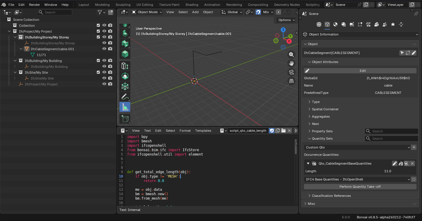
I made a hack for cable lengths:
1- Model the cables as an extruded mesh vertex
2 - Assign class ifc
3 - Run the attached script to calculate the lengths and create qto values
The only problem is that you can't edit the mesh afterwards, I think it's a bug.
@walpa said:
I made a hack for cable lengths:
1- Model the cables as an extruded mesh vertex
2 - Assign class ifc
3 - Run the attached script to calculate the lengths and create qto values
The only problem is that you can't edit the mesh afterwards, I think it's a bug.
Amazing!
Do you think we could use that code together with meshes created by nodes?
My take is something like that: we could load the IFC file and work with it outside bonsai at first to speed editing, draw on the surfaces of walls and ceilings the paths of conduits with the desired amount of cables set by a geo node tree, than convert the generated mesh to IFC and later import into the main file again.
Something like that:
If it is possible, the challenges I think would be something like:
How to set a conditional input in the node, like
How many circuits in this conduit? 3
Id of each? 2, 4, 5
-- circuit 2, how many cables? 3
---radius of the cables? 2 mm
---grounded? yes no
----if yes, radios of ground cable? default same as above but changeable
--circuit 4, how many cables? 4
same
--circuit 5, how many cables? 2
same
Then if we could group all the cable meshes and export them to IFC in order to calculate the length of each type, we would have the BOM of cables.
Am I making any sense?
(I don't know much about nodes nor how or if it could integrate with bonsai, in this quick example I could not even conceal the cables inside the conduit properly, but I trust you all are way better skilled than me.)
Do you think we could use that code together with meshes created by nodes?
It doesn't work; for a cable modeled with a "cylindrical" mesh, the script would accumulate the lengths of all the edges. In your example, 1 cable would have 6 * n edges of length + n * 6 edges forming the circles.
My take is something like that: we could load the IFC file and work with it outside bonsai at first to speed editing, draw on the surfaces of walls and ceilings the paths of conduits with the desired amount of cables set by a geo node tree, than convert the generated mesh to IFC and later import into the main file again.
GN is a modifier, so the geometry to be used for conversion to IFC only exists after applying the modifier. This means you lose the parameterization anyway.
If it is possible, the challenges I think would be something like: ...
I don't think it's possible to create a group node that allows creating parameters dynamically. I'm not an expert in GN, but I haven't seen anything like this in all my research.


Comments
Where is your faith man? A few years ago the same could be said about multilayered walls or accurate textures in complex facades. Let's freely dream and hope for the efficiency wizards to perform their craft. I'm a bit traumatized by that cause people normally say it is not needed for electrical modeling because it's hidden inside the walls, it aways frustrates me a bit. The point is precisely achieving the superpower of being able to see through the walls at any time.
But seriously though, would it be gorgeous for the 5 seconds it would last before combusting?
I hope these are proper profile IfcColumns and IfcBeams ;)
Passing by to better illustrate to our fellow developers my child dream on electrical projects.
I'm now modeling a house for a friend and once again I wish I could do everything in blender beautifully as my heart desires.
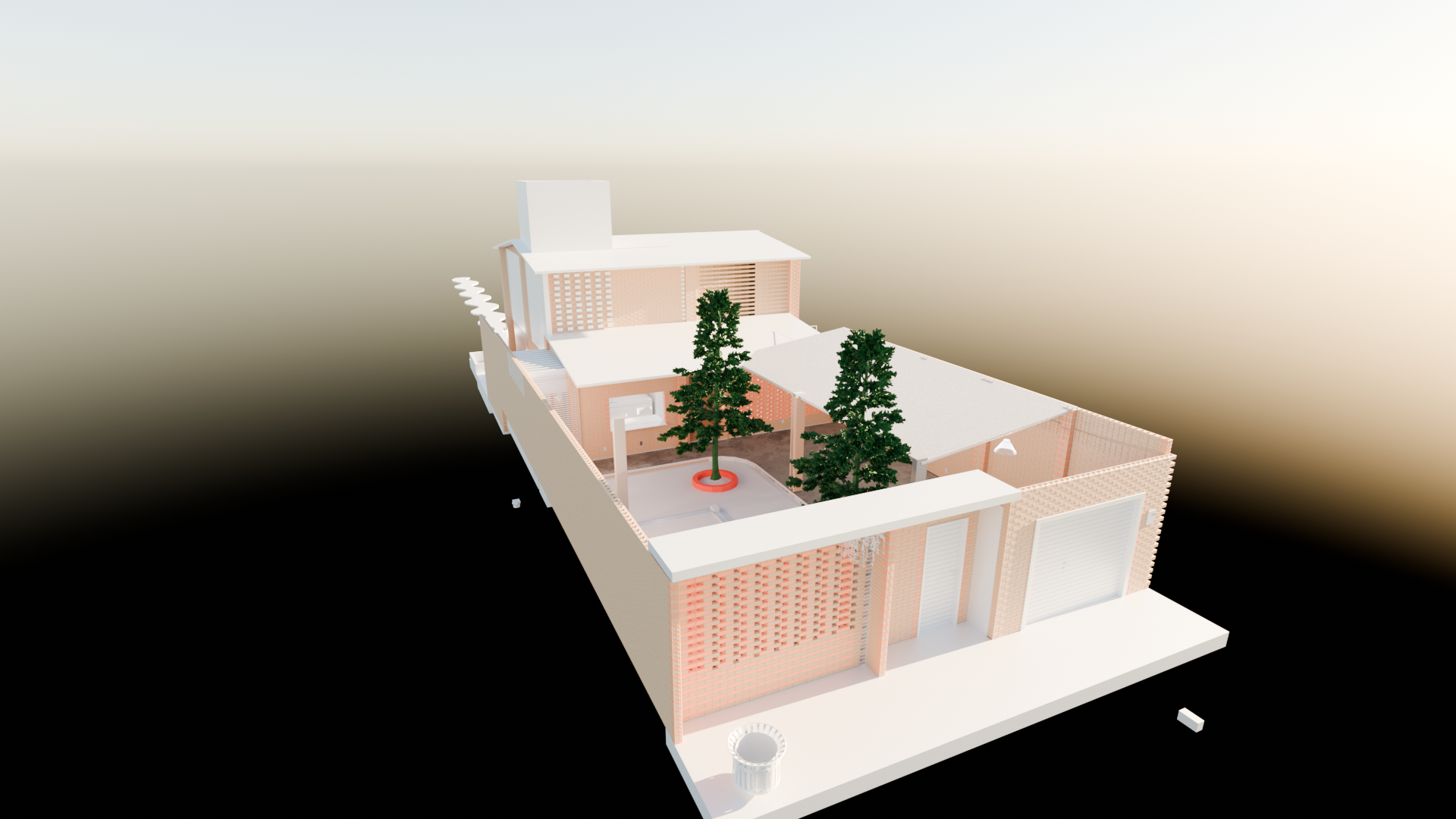
He made the architectural design in Revit and exported the IFC to me. He is like me also autistic so he modeled in a way so that every ecobrick has its own geometry hahaha and well, It's gorgeous.
So I started designing the electrical systems within and for some reason my bonsai is really lagging on every insert of a new element :`(
(I know Mac is not the best to model, but I have a M3 Pro chip, and everything else goes rather fast)
I'd say pain by pain it is advancing
The thing is, I can't make amends in my mind with the impossibility of modeling the entire electrical system inside blender, just makes so much sense that I should be able to do it easily. So I tried with a lot of love and anxiety. This is what I managed to do so far:
I just modeled the main electrical boards, electrical points such as outlets and light fixtures.
Main annoying things so far:
Being unable to change the view angles while placing elements hurts and ends up demanding a lot more clicks than it could. I wish something like what the CAD Transform add-on allows: visibility free to move while modeling;
I still can't find a good way to connect conduits better than drawing from the junction box to a ceiling reference such as a light fixture, and after that from the end of the conduit to the final destination. If I could make a turn like in a Bézier curve it would be great. Sadly as profiles don't seem to allow this, and I particularly don't find useful the fitting and curves in light weight conduits, they keep on not well aligned;
Blender crashed a lot of times, mostly when I tried to import IfcProducts from previous projects or downloaded online. For some reason it would crash, forget the reference to the new inserted elements but keep their unlinked geometry in the viewport. It felt like death every time;
And what keeps me awake at night: how can I derive the cables quantities later on?
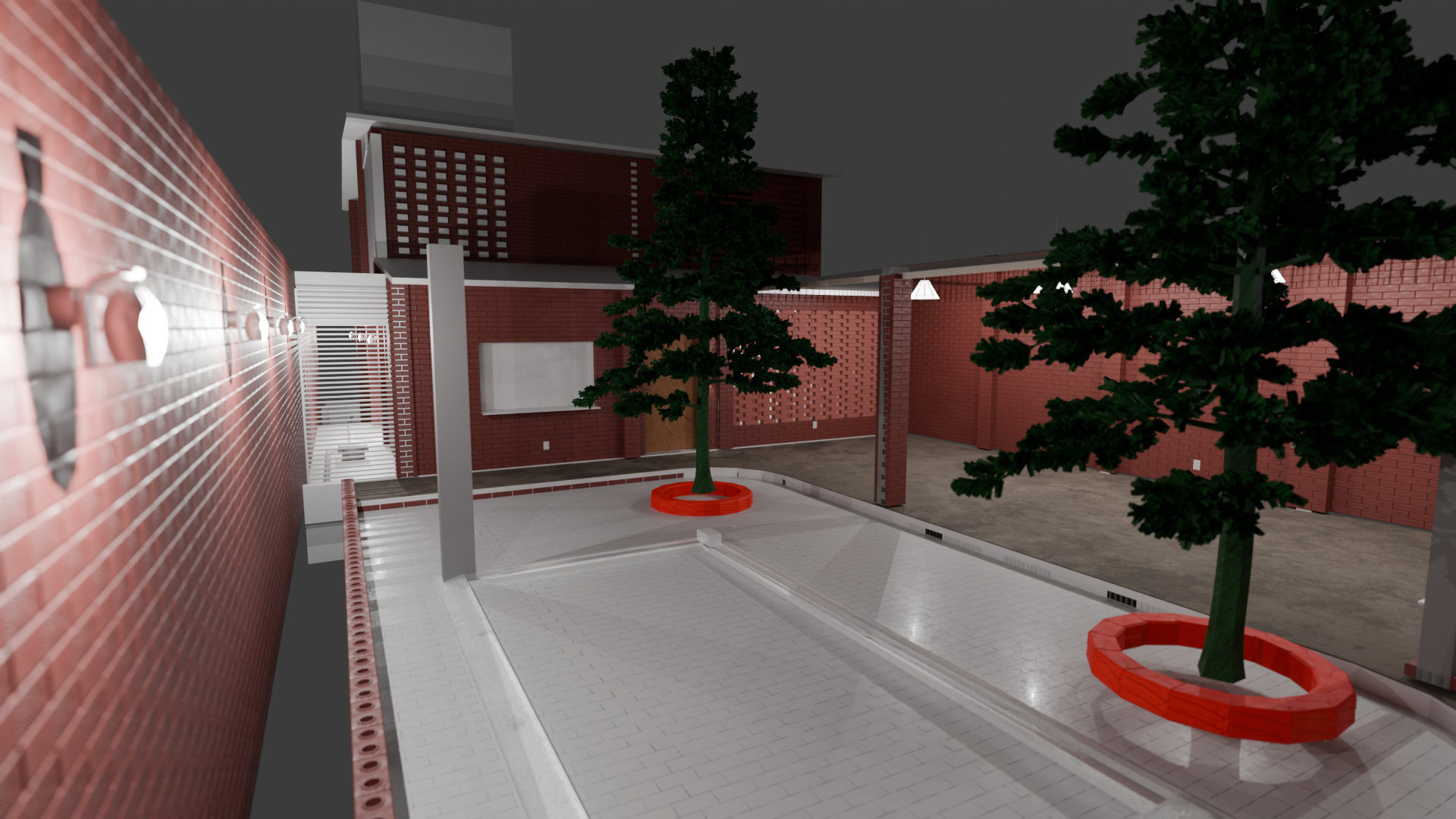
So I make a test in a way smaller scale to show how amazing electrical design can become if made a little bit less time consuming in the future:
Imagine an electrical engineer discussing with clients of fellow engineers and trying to explain why it's needed 5km of cables in a small building, and the sadness that comes when no one else can see the need for that many cables from your flat pdf drawing and not even from in the BIM modeling hidden in layers of info inside empty walls and emptier still conduits. Well, cry no more, what if there was a tool bringing light to it all?
A truly detailed board so the execution and client can read it without the need for a single-line diagram translation.
Than an X-Ray to see what hides beneath the bricks
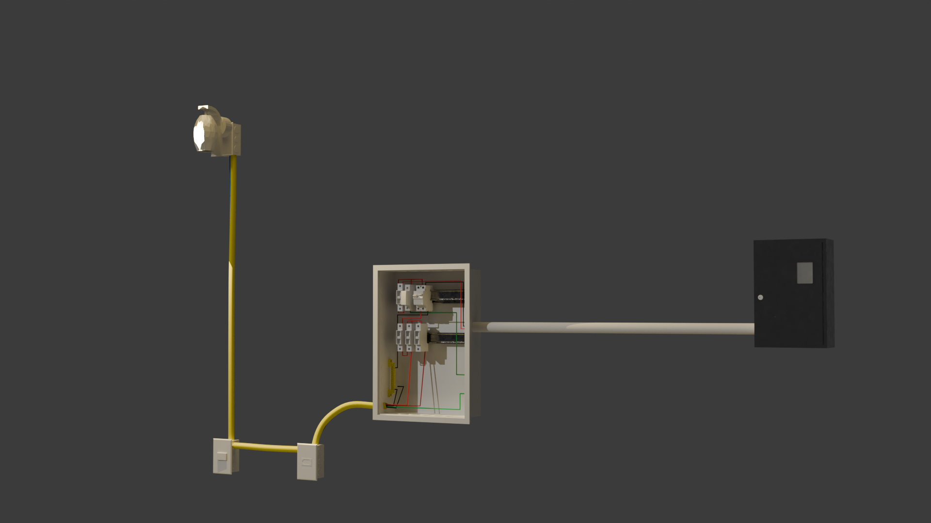
And the angels of my dreams in all its glory inside the conduits showing where each cables starts and ends, no space to mistakes, true amount of cables inside to verify occupancy rates, accurate BOM for cables, beautiful as everything else. Please haha
For this I used some geometry nodes for the wires and the extra curves addons to extrude bezier and polys. It's still really time consuming.. the cables are not converted in IFC elements and because of that I did not use the systems to isolate the circuits, nor I can derive the lengths (I think). But if it serves as inspiration to someone in order to perfect a more efficient workflow in this regard, I could see all of our kind invading blender for good.
I'll leave here the blend and ifc (change of plans hahahah seems like some instance was lost and I can't export the ifc) files for the demo.
But here goes the .blend: GDrive
There's not many BIM modeling programs in the world, that could handle this level of detail for an entire house. :)
I know it's painful to compromise, but would suggest abstracting your geometry down to simple prismatic diagrams.
In my mind, when trying to determine how detailed something needs to be, I ask, "does the contractor really need this level of detail, to understand the design intent"?
this is currently a bug, i think: https://github.com/IfcOpenShell/IfcOpenShell/issues/7374
Currently what is the best workflow available in blender and bonsai, I mean to calculate the electrical wire need according to the thickness of each, how should we proceed?
Tried modelling the conduits using IfcCableCarrierSegment, but through conduits several wires go to and fro, and thus wire length calculation cannot be derived correctly from it. Is there an efficient and better workflow.
@arunarchitect
as far as I know there is no method at the moment to have a polyline-like (line, arc) geometry from which you get its length value to populate Qto_CableSegmentBaseQuantities.Length, from start to end.
But you can use a number of straight (connected port to port) segments from extruded profile instead, kind of clunky but doable for quantity take-off.
If cables are part of a system/circuit, also leveraging Pset_CableSegmentTypeCableSegment.NumberOfCores (I wouldn't personally go as far as modeling every single one like in the beautiful @engcleberfeitosa 's model), you can have some approximate length.
Or you can use IfcCableCarrierSegment and note the cables running into it as custom property
Let's see what our Electrical specialists here can add
Cheers
I made a hack for cable lengths:
1- Model the cables as an extruded mesh vertex
2 - Assign class ifc
3 - Run the attached script to calculate the lengths and create qto values
The only problem is that you can't edit the mesh afterwards, I think it's a bug.
Amazing!
Do you think we could use that code together with meshes created by nodes?
My take is something like that: we could load the IFC file and work with it outside bonsai at first to speed editing, draw on the surfaces of walls and ceilings the paths of conduits with the desired amount of cables set by a geo node tree, than convert the generated mesh to IFC and later import into the main file again.
Something like that:
If it is possible, the challenges I think would be something like:
How to set a conditional input in the node, like
How many circuits in this conduit? 3
Id of each? 2, 4, 5
-- circuit 2, how many cables? 3
---radius of the cables? 2 mm
---grounded? yes no
----if yes, radios of ground cable? default same as above but changeable
--circuit 4, how many cables? 4
same
--circuit 5, how many cables? 2
same
Then if we could group all the cable meshes and export them to IFC in order to calculate the length of each type, we would have the BOM of cables.
Am I making any sense?
(I don't know much about nodes nor how or if it could integrate with bonsai, in this quick example I could not even conceal the cables inside the conduit properly, but I trust you all are way better skilled than me.)
@engcleberfeitosa
It doesn't work; for a cable modeled with a "cylindrical" mesh, the script would accumulate the lengths of all the edges. In your example, 1 cable would have 6 * n edges of length + n * 6 edges forming the circles.
GN is a modifier, so the geometry to be used for conversion to IFC only exists after applying the modifier. This means you lose the parameterization anyway.
I don't think it's possible to create a group node that allows creating parameters dynamically. I'm not an expert in GN, but I haven't seen anything like this in all my research.