

The Seed. :)

    /*#19= IFCPRODUCTDEFINITIONSHAPE($,$,(#15));*/
      /*#15= IFCSHAPEREPRESENTATION(#9,'Body','SweptSolid',(#18));*/
        /*#9= IFCGEOMETRICREPRESENTATIONSUBCONTEXT('Body','Model',0,$,$,$,#3,$,.MODEL_VIEW.,$);*/
          /*#3= IFCGEOMETRICREPRESENTATIONCONTEXT($,'Model',3,1.0E-05,#8,$);*/
            /*#8= IFCAXIS2PLACEMENT3D(#14,$,$);*/
              /*#14= IFCCARTESIANPOINT((0.,0.,0.));*/
        /*#18= IFCEXTRUDEDAREASOLID(#21,$,#22,2000.);*/
          /*#21= IFCRECTANGLEPROFILEDEF(.AREA.,'1m x 1m rectangle',$,1000.,1000.);*/
          /*#22= IFCDIRECTION((0.,0.,1.));*/
@yorik , @Moult
Possible to roundtrip just this between Freecad and Blender, and maintain all the parameters through strict implementation?
We'll call it the 'The Seed!' :)
Thoughts?
Tagged:
Comments
@theoryshaw Blender currently doesn't read the rectangle profile def. It'll convert it to an arbitrary polygon (which may happen to be identical to a rectangle). Perhaps this is something to fix first?
FreeCAD can export exactly that above, but last time I checked, Revit had problems reading the IfcRectangleProfileDef entity. So there is even an option to disable it in FreeCAD (all profiles are then exported as IfcClosedArbitraryProfileDef). What happens at import, at the moment, extrusions are recreated, but the base profile is not a rectangle anymore, but a polyline. We could actually add a check to turn it into a rectangle if applicable... I'll have a look at that. Then I think we'll have 100% back-and-forth compatibility with the above.
Very cool.
Yeah, i don't think we should worry about trying to accomodate a strict roundtrip with Revit anymore--unless someone could do a ground up converter through Dynamo or Revit's API where we could more easily maintain a strict implementation.
Thoughts?
It sounds like @yorik's implementation in FreeCAD, my implementation in Blender, and Revit's implementation all ignore the rectangle profile def and use a regular closed profile. Maybe we can round-trip that instead?
Yes, IfcClosedArbitraryProfileDef sounds a like a good seed as well.
Any thoughts on what we can call this strict implementation initiative? FreeMVD?
Eitherway, I suggest not trying to bend over backwards to get Revit to comply as well. Unless we can find someone to implement a ground up converter through Dynamo or Revit's API. In my experience, feature requests to IFC for Revit, fall on deaf ears--i've tried a lot over the years and nothing.
We could setup a series a goals, or a kind of roadmap... What about this? https://github.com/OpeningDesign/FreeMVD_WorkFlow/blob/master/IFC_roundtrip_specifications.md
This is great!
@yorik , can you put (2) cubes in your FreeCAD file, one extruding in the Z and one extruding in the y or x?
I just know Revit won't obey extrusion direction, so I can show that it FAILS. ;)
Also, can you add a 3rd freecad file, where you import your IFC back into Freecad? I think that's valuable documentation to see, as well--as that demonstrates the 'roundtrip'.
Excited.
@theoryshaw We discussed it before, here:
https://forums.buildingsmart.org/t/why-are-csg-representations-mandated-for-dtv/2311
Hope helps with
@theoryshaw I think Revit does obey extrusion direction, and I've implemented it - but I'll wait for @yorik's file first.
Okay I made another test file, with 3 extrusions, one vertical, one horizontal and one in another arbitrary direction: https://github.com/OpeningDesign/FreeMVD_WorkFlow/blob/master/IFC_roundtrip_specifications.md#2-importing-and-exporting-non-vertical-extrusions
Next step could be working with circle or rectangle-based extrusions...
I reorganized a bit
https://github.com/OpeningDesign/FreeMVD_WorkFlow/tree/master/Specifications_Test_Files/Extrusions
Proposing we show pass fail on the file itself. Would require less upkeep on the 'table'.
With files, we can show the branching of various import/export 'paths' in and out of various programs.
...
I also deleted the simple extrusion test, as that would be tested for in the 'multiple extrusion' test... just less stuff to maintain.
...
@Moult, yes Revit imports extrusion directions correctly, but does not export them correctly. :\
...
Please let me know if you have any push back on this proposed way of organizing... i'm sure the structure of how we organize these tests will change quite a bit over time anyway.
...
Yes, agree with @yorik circles, and arcs, would be a nice next test.
Also, forgot to mention, Using the IFC-commenter I added corresponding 'commented' IFC to the tests as well. It helps me to understand the file's structure and run trail/error scenarios on the file. Let me know if that's helpful to others as well.
Just logging here. Requests to correct extrusion direction in Revit...
How about the following file naming logic?...
https://github.com/OpeningDesign/FreeMVD_WorkFlow/blob/master/File Logic Examples.csv
Moved the suggested file naming conventions to markdown: https://github.com/OpeningDesign/FreeMVD_WorkFlow/blob/master/IFC_roundtrip_specifications.md#file-naming-convensions
Looks good! But since this is about import and export, i would expect every app to produce its "seed file".. would that fit in your naming scheme?
Hi @yorik, sorry for the delay, it's been a crazy week.
Are you thinking each application, would recreate, from scratch, their own native test file? If so, I can see that getting complicated. Would be hard to verify and assure that the originating author creates their particular native file exactly as someone from another native application.
Having said that however, as we get into this, it just might be necessary to do this. If so, perhaps at that point we can use folders for each native file seed.
Yes, i would think creating a file from scratch might give different results than importing the ifc file, and then it could be interesting to compare.. but yeah then we'd need to describe better what needs to be modelled.
I added a BlenderBIM test for giggles. :)
https://github.com/OpeningDesign/FreeMVD_WorkFlow/blob/master/IFC_roundtrip_specifications.md#results
@yorik possible to add your 'Extrusions_03.FCStd' file?
That is...
Extrusions_01.FCStd --> Extrusions_02_PASSED.ifc --> Extrusions_03_PASSED.FCStd
I will try BricsCAD IFC BIM :)
Extrusions_01.FCStd --> Extrusions_02_PASSED.ifc -->
Cannot import file: C:\Users\Admin\Documents\IFC\Testing SEED\Extrusions_02_PASSED.ifc (Failed to read IfcModel from C:\Users\Admin\Documents\IFC\Testing SEED\Extrusions_02_PASSED.ifc.
See C:\Users\Admin\Documents\IFC\Testing SEED\Extrusions_02_PASSED.ifc.in.log for details)
It just says..
Parser Error at 7.11: syntax error
Yeah ... I do need to improve the geometric representation round-tripping in Blender ...
When importing this file into blender28-bim-200525-win I get the following error...
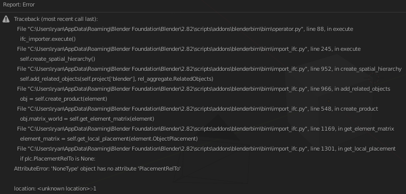
@theoryshaw the reason for that is because the IfcBuilding does not have any object placement. Theoretically, the IfcBuilding does not need an object placement and the specification says that it is optional, unless it has a representation.
However, there is an implementer agreement required for certification that contradicts this, that states that vendors should create a relative placement equivalent to the spatial tree. It looks like FreeCAD does not honour this implementer agreement, resulting in that error.
I could accommodate it, or maybe FreeCAD should fix it? Not sure, buildingSMART has left this a bit ambiguous. Thoughts, @yorik?
If you look at the others agreements there (press the "next" button), there are all kinds of strange things (roofs MUST be assemblies, "geo coords should be exported if they are available, otherwise they shouldn't be exported"), honestly I think it will give us a lot of headache if we begin to need to check manually these kind of non-standard standards... Specially when we have a schema, that clearly says what can and what cant, that is usable by a machine, and that is implemented by IfcOpenShell so it automatically doesn't allow things not allowed by the schema. My opinion is more that these things are meant for future versions of IFC, and we should follow them when they are part of the schema.
We could make "empty" buildings have a default placement in FreeCAD's IFC export, it's not a big deal, but it seems to me we would unnecessarily be adding superfluous information to the file...
I agree that the implementer agreements need some rethinking ... there was a recent decision to merge the agreements into the spec, and that might be the prompt to reconsider some of these agreements.
In any case, FreeCAD's behaviour is not illegal, so I'm now supporting it :) https://github.com/IfcOpenShell/IfcOpenShell/commit/bdf17e5c122720c64f048af17c3cbff1ea4ec582
Good way to solve things @Moult ... IMHO it's cool that apps are tolerant to IFC "dialects"...
I added FreeCAD files for @Moult 's second test (mapped items) which I'm happy to say FreeCAD passed easily ;) and added a third test (extrusions of circles and rectangles), which of course BlenderBIM will probably fail, as these entities don't exist in Blender, but it seemed to me an interesting topic to look at anyway, since it is something we discussed earlier already... So maybe this is a good opportunity to try to tackle it in some way...
@yorik, in the latest commit, I'm proposing to break out the extrusion tests into more grandular tests. That is...
I feel having a (1) test with both rectangles and circles added too many variables by which to test against. Have just (1) profile typology in one (1) test makes it easy to report what in that test worked, or not.
As you can see, I'm proposing to create a new OSarch thread for each test as well.
Excellent idea!