@arquitextonica
What you might not have realized about Freecad is that it's Sketches are parametric geometries that are the foundation for a Freecad model. Change the parametric relationships between a sketch and all the model changes accordingly. It's way more powerful than a set of 2D polylines. It's an incredible methodology. Having sketches have a meaning and having topologic build everything else beyond sketches, based on that meaning, would be amazing.
@brunopostle
I think it's very interesting to think on a tool to develop standard architecture in a zip if that's what you're aiming for. However, topologic allows for much more and what's brilliant about the future is how we can free ourselves from constraints. When all software is capable of creating standard architecture with 2 clicks of the mouse, what will matter is creativity and the freedom that software will allow the human mind. I'm interested in that and I'm afraid of making the standard way of doing things too easy, as it might result in the production of the average. Your work is amazing but I would love to see it with a wider scope. If Topologic allows it, why not?
@brunopostle said:
This isn't too hard a problem, I solved it in 3d for my previous Topologise tool. Basically iterate through all your lines, allocate a 'room' to the left and to the right of the line, then propogate this information to adjacent lines until there are no lines left. Alternatively, you could convert to 3d and let Topologic [edited] sort it out for you.
I try to imagine, not sure I understand how to move forward :)
Say, below layout, 6 edges ( 3 'vertical', 3 'horizontal'). It defines 4 areas.
I can't figure out the algorithm to find out the 4 areas automatically. Currently, I need to do that manually - i.e. pointing out which 4 edges define an area and need to do that 4 times :(
@paullee said:
I try to imagine, not sure I understand how to move forward :)
Say, below layout, 6 edges ( 3 'vertical', 3 'horizontal'). It defines 4 areas.
I can't figure out the algorithm to find out the 4 areas automatically. Currently, I need to do that manually - i.e. pointing out which 4 edges define an area and need to do that 4 times :(
This is a very easy workflow for Topologic. Feed the edges into a Cluster, self-merge it, and feed it to wire-cycles with maximum 4 vertices (this is a custom node written in pure python available on TopologicDynamo. Planning to port it to Blender/sverchok. It will return 4 closed wires.
@arquitextonica said:
Amazing work @paullee. I´m currently working on my thesis and my research approach is almost identical to yours, though I got some advantages from the tools. I´m working with Rhino and GH and there the 2D bounds recognition algorithms are already strong and stable, and above all, @topologic gives a lot of strength.
So as I saw you already built the spaces from the edges, I´ll throw my two cents.
I´m currently working by making closed space contours with 2d polylines. I then convert it to a topologic object with properties dictionaries and operate within them. Then, the resulting objects have properties dictionaries and allow me to perform topological operations among them. The result for me is very interesting because through the overlap of the properties, new properties can airse and we get "emergence" for design.
I do not know Revit, Rhino, GH etc. except AutoCAD probably upto 2008, and recently FreeCAD (on Fedora linux) :D
I am trying to understand the capabilities of Topologic, and see if and how the worflow in FreeCAD / daily Architect design development could fit in. Maybe you can show more what you are doing to demonstrate your idea ? Thanks in advance.
BTW, there is an software called TAD which seem have similar concept - Room/ Space as fundamental building block of design development.
@paullee Since you are on Linux you can download and install topologicPy from http://github.com/wassimj/topologicPy
Then you have five options:
1. Use pure python scripts from the console to read and write BREP objects (100% compatible with FreeCAD)
2. Use python scripts within FreeCAD
3. Use python scripts within Blender
4. Use sverchok Topologic visual nodes in Blender (coming soon)
5. Same as #4 but integrate with FreeCAD sverchok nodes.
@JQL said:
I think it's very interesting to think on a tool to develop standard architecture in a zip if that's what you're aiming for. However, topologic allows for much more and what's brilliant about the future is how we can free ourselves from constraints.
This is what you will be able to do with Topologic Sverchok nodes or the equivalent. The tool I have in mind needs to go further and, as I said, 'anything-goes-in-free-jazz-architecture' imposes some severe constraints.
@paullee basically, you get the line equation for each of the edges, and with this you can determine which of the other nodes are 'above' or 'below' the line. But if you are coding this in python, Topologic exists to solve these sort of problems for you.
I can't figure out the algorithm to find out the 4 areas automatically. Currently, I need to do that manually - i.e. pointing out which 4 edges define an area and need to do that 4 times :(
This is a very easy workflow for Topologic. Feed the edges into a Cluster, self-merge it, and feed it to wire-cycles with maximum 4 vertices (this is a custom node written in pure python available on TopologicDynamo. Planning to port it to Blender/sverchok. It will return 4 closed wires.
Sounds great :D Need to tell Topologic the numbers of vertices say 4 to form an area ?
@paullee 4 is to limit the search. As you can imagine your diagram can have many sub-shapes. But if you don’t want to do that, you can extrude the lines up to faces, then call CellComplex.ByFaces then call CellComplex.Cells and it will automatically give you four cells. If you want the floor, just extract the face that has a face normal with Z less than 0 (usually -1).
@paullee Here is how it would look in Topologic. Read the graph from left to right. It generates 6 lines as you specified, it makes them into a Cluster, then self-merges the Cluster yielding a Wire then fed into Wire.Cycles to detect closed cycles of maximum number of vertices (in this case 4) and then convert into faces and geometry to display. At the end I move them apart so you can see them.
I wonder if Topologic will be able to read FreeCAD sketches. They are not actual geometry, they are only geometric rulers/constraints... I might be wrong.
@JQL said:
I wonder if Topologic will be able to read FreeCAD sketches. They are not actual geometry, they are only geometric rulers/constraints... I might be wrong.
I am not sure. Topologic can read BREP files. If you send me a sample file, I have FreeCAD and can test it.
@JQL@topologic Seems better idea than I attempt to compile Topologic without much experience in this :D
Seems FreeCAD file *.FCStd is not accepted, I just rename the extension to *.zip for uploading - pls rename back to *.FCStd
Ok, there is a Sketch object, with 6 edges.
Then, make extrude to make 6 vertical faces, 1 bottom face and 1 top face from the edges - all in a Group folder.
There is an Edges Group folder. All the edges in the original Sketch are made into individual Part Shape, if you may have problem to work with the Sketch Object :D
Thanks in advance !
(remember to rename the attached FC file into *.FCStd to open)
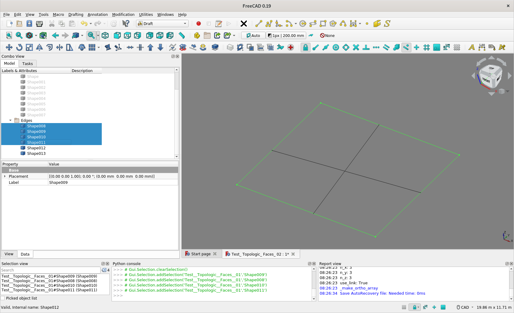
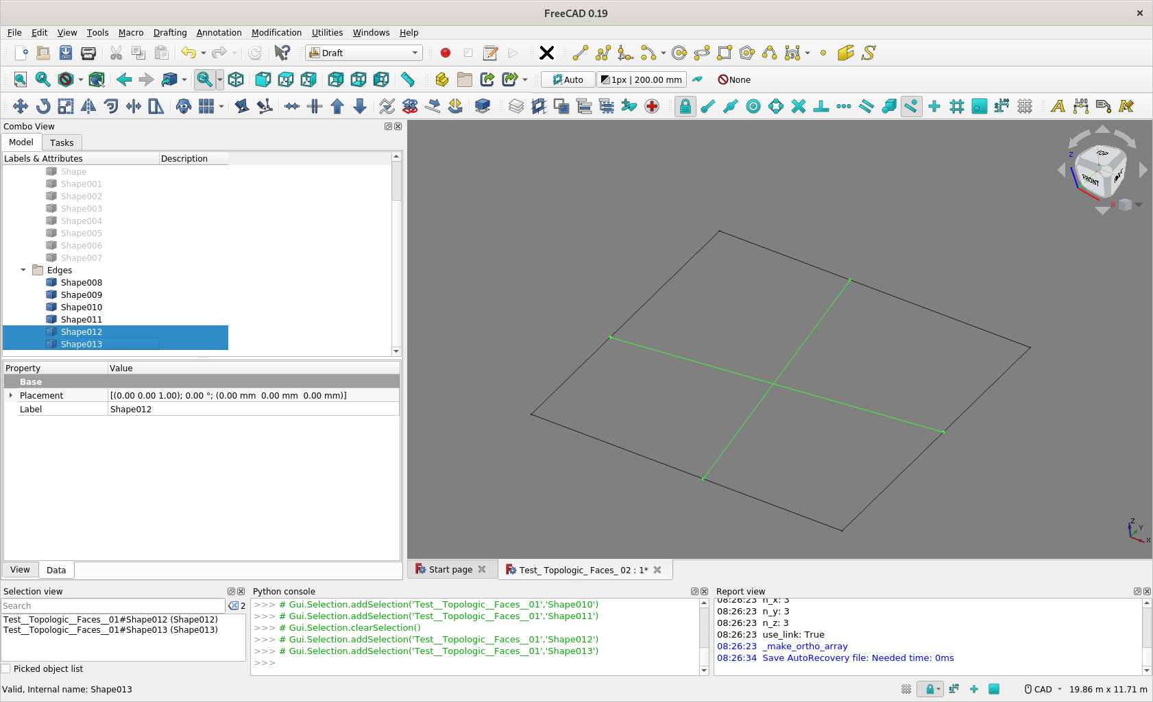
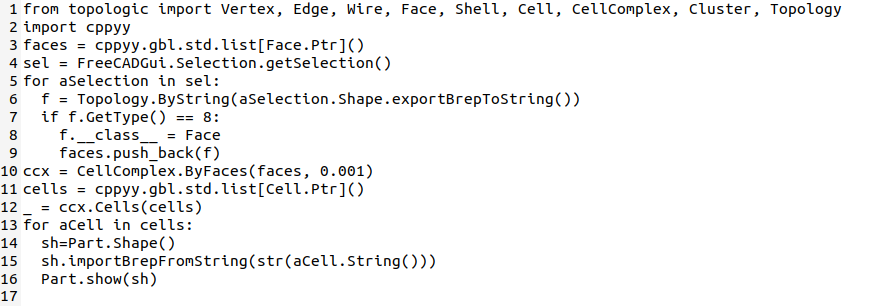
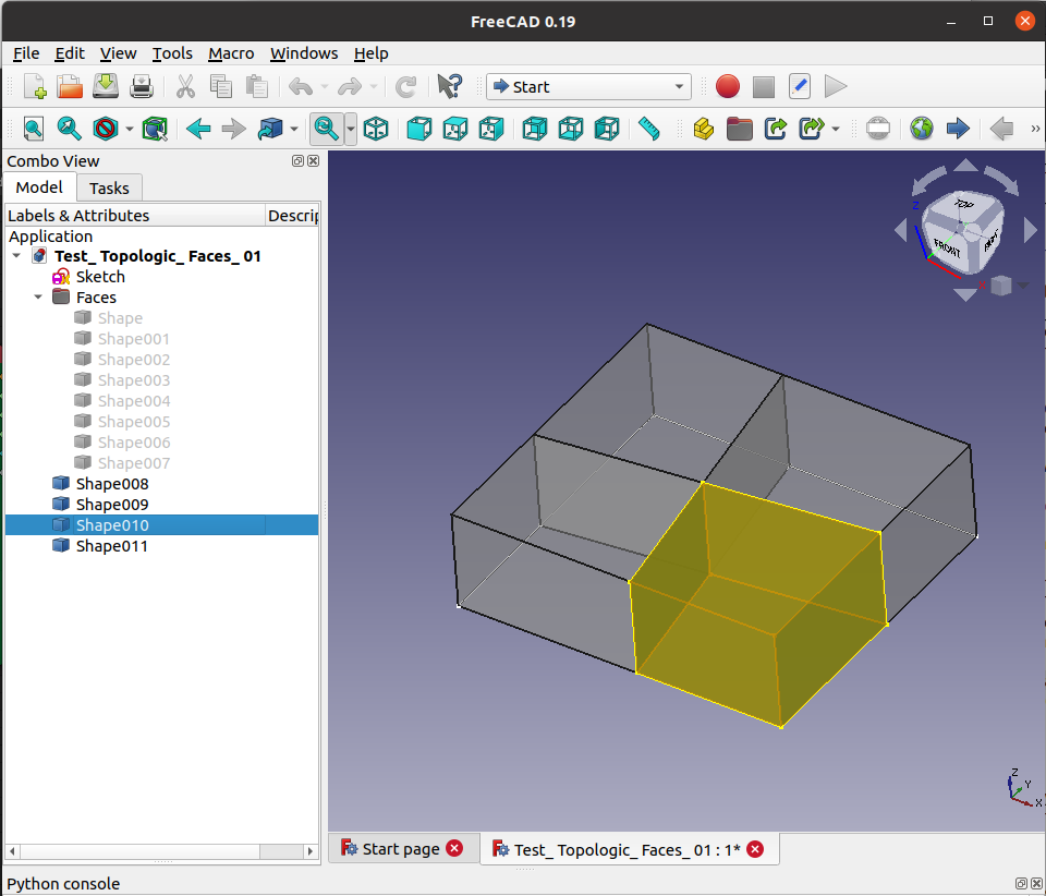
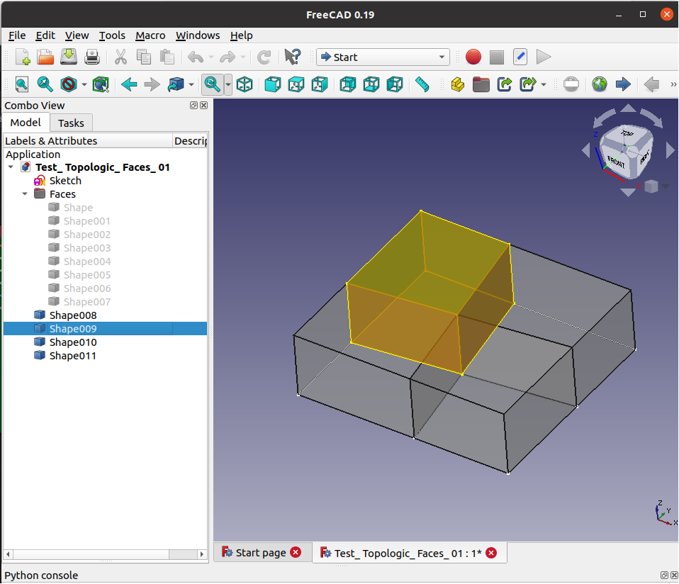
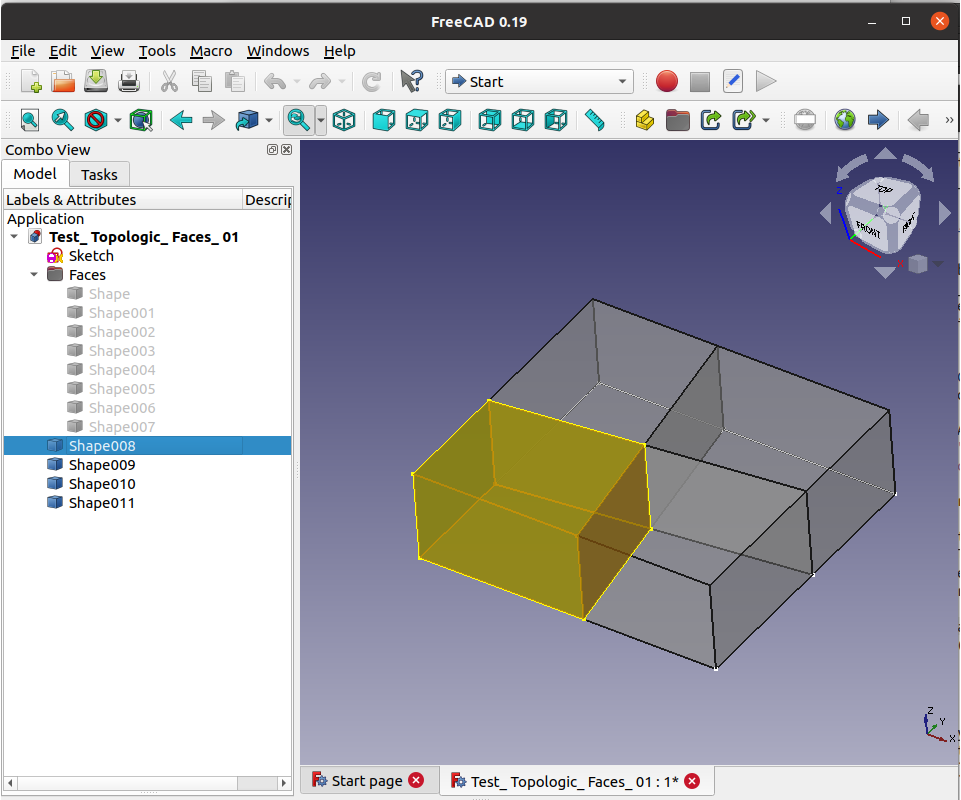
@paullee This was quite easy for Topologic in FreeCAD. Mainly, first make sure the 8 surfaces are selected and then paste the following python code:
You get the four Cells converted into four new Parts
@topologic said:
You get the four Cells converted into four new Parts
Gorgeous !
Hope can use that right in my FreeCAD :D
1 Question at the moment - can you relate back to which 4 (or 6 faces) in FreeCAD shapes each of the generated Cells came from ?
Thanks.
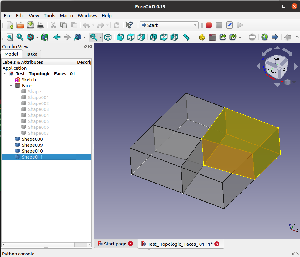
I selected Shape --> Shape007 and then pasted the python script in the python console. It creates Shape008, Shape009, Shape010, and Shape011 automatically from the original 8 Faces.
If you are on Linux, try to follow the instructions on github.com/wassimj/topologicPy and if you have FreeCAD 0.19 daily, it should work. The tricky part is always installing cppyy and all its dependencies, but I think the recipe I have on github is good. Myself, Theo Dounas and @brunopostle have been able to install Topologic and cppyy on Linux and it works great. My setup is python 3.8, Ubuntu 2.10 Groovy Gorilla and FreeCAD 0.19 daily build.
Oh sorry. I did not understand your question! You mean to go back to the original faces. This would be a geometric workflow of testing if the two faces are co-planar and identical etc.. For simple cases, you can compare their centroids and that might be enough perhaps (if the original face was not cut up into smaller pieces). In principle, it is possible like this:
1. For each Cell in the result:
2.----For each face in the Cell:
3. -------- Get a vertex guaranteed to be inside (Face.InternalVertex())
4. ------------ For each face in the original list:
5. ----------------Is the internal vertex inside the original face in question?
6. -------------------- If so, copy attributes from that original face to the cell face.
1 Question at the moment - can you relate back to which 4 (or 6 faces) in FreeCAD shapes each of the generated Cells came from ?
This would be a very useful feature, for the elements of the cell complex to inherit any attributes (as a dictionary) of the original objects.
Hi @brunopostle Here it is :). I didn't bother with dictionaries, but the principle is the same. The 20 derived faces are checked against the original 8 faces. If they match, the name and the color is transferred to the new face. If you look closely and count, you will notice that 2 of the original faces (top and bottom Shape and Shape007) yield 4 new faces while the other faces yielded 2 new faces.
@topologic said:
Hi @brunopostle Here it is :). I didn't bother with dictionaries, but the principle is the same. The 20 derived faces are checked against the original 8 faces. If they match, the name and the color is transferred to the new face. If you look closely and count, you will notice that 2 of the original faces (top and bottom Shape and Shape007) yield 4 new faces while the other faces yielded 2 new faces.
Thanks taking the time to explain :D This is exactly what I mean.
Though I thought it do not require the user to test by going through the loop you indicates ? During the process Topologic identify the 4 resultant Cells, would it already know which 6 Original Faces creates that 'boundary' ?
It is apparent to a human being, 2D on the Sketch or 3D of the 8 Faces - that's the algorithm to find the 4 'boundaries' in 2D Sketch I would like to know - the same feature in AutoCAD to do Hatch / find boundary ?
Not only as @brunopostle point out that attributes can inherit, but the Original Edges and the Resultant Cells / Faces can 'co-relate' to each other. For example, user may do a script to ask Topologic to deduce what faces are External, then assign back desirable materials / thickness / reflectance to the Original Faces / Edges (Wall / Curtain Wall ) and the elements it contain (Window / Spandrels / Cladding / Insulation).
Just some random thoughts :)
Hi @paullee, There isn't a way to relate the faces without a search. The subdivision of an orginal face to create the faces of the cellComplex is buried deep in opencascade's engine, so we need to do this after (not during) the creation of a CellComplex from a list of Faces.
What you write in the last message is exactly correct: Now that we have built the CellComplex, we can ask questions such as:
1. For a given Cell in a CellComplex, give me the list of its adjacent Cells?
2. For a given Face in a CellComplex, give me the two Cells that it separates (or one Cell if it happens to be an exterior Face).
3. For a given CellComplex, give me the outer faces and the inner faces in separate lists (you can further divide by vertical vs. horizontal)
4. For a given Face, give me the apertures and other contents that it may contain.
The above are just examples. We can think up other more advanced queries that can be readily answered by Topologic. For example, for a given Cell in a CellComplex, how central or how isolated is it?
@topologic said:
Hi @paullee, There isn't a way to relate the faces without a search. The subdivision of an orginal face to create the faces of the cellComplex is buried deep in opencascade's engine, so we need to do this after (not during) the creation of a CellComplex from a list of Faces.
What you write in the last message is exactly correct: Now that we have built the CellComplex, we can ask questions such as:
1. For a given Cell in a CellComplex, give me the list of its adjacent Cells?
2. For a given Face in a CellComplex, give me the two Cells that it separates (or one Cell if it happens to be an exterior Face).
3. For a given CellComplex, give me the outer faces and the inner faces in separate lists (you can further divide by vertical vs. horizontal)
4. For a given Face, give me the apertures and other contents that it may contain.
The above are just examples. We can think up other more advanced queries that can be readily answered by Topologic. For example, for a given Cell in a CellComplex, how central or how isolated is it?
Thanks, I can partly understand the mechanism when you mention underlying process is done by OCC :D Just curious what the algorithm do ?
I do not know much about OCC, it is the core of Part WB in FreeCAD to my understanding. I see there are methods (exposed in python too) like childShapes(), isSame(), isEqual() that may help to trace the history of OCC operation. The method to check the correlation become significant if the workflow start with an Object in FreeCAD, rather than starting from Topologic, I think ...
And maybe Topologic can find the escape path in a labyrinth ? :D
@paullee The workflow I demonstrated does start with FreeCAD objects and returns FreeCAD objects. Anyway this is how it can be done in Topologic, but if someone can hack OCCT that would be impressive (OCCT is notoriously difficult and low level), but I doubt that is the right way to do it when you can write it easily in a few lines of code. That’s why people use libraries: to work at a higher level.
Thanks @topologic, I understand! Impressed very much by the capabilities of Topologic. Would try the codes you shows when I manage to compile and run it here :D
So if it can run in and sort out a maze (labirynth) , then topologic can 'reanalyse' any IFC ? and redefine it, and correct what was wrong. The (imperfect) IFC -tree (graph) is then replaced by the Topologic-tree, which of course can be rewritten as IFC.. the IFC-correction-tool ? The import/export tool for all BIM authoring softwares.. depending on the dictionnary settings..
@lukas said:
So if it can run in and sort out a maze (labirynth) , then topologic can 'reanalyse' any IFC ? and redefine it, and correct what was wrong. The (imperfect) IFC -tree (graph) is then replaced by the Topologic-tree, which of course can be rewritten as IFC.. the IFC-correction-tool ? The import/export tool for all BIM authoring softwares.. depending on the dictionnary settings..
I don’t know enough about ‘problematic’ IFC to know if Topologic can correct them, but happy to collaborate and test.
@paullee said:
Would try the codes you shows when I manage to compile and run it here :D
Are you on fedora Linux? I have built rpm packages of all the Topologic dependencies (except for topologicPy itself, but this is the easy one). Currently f32, f33 & f34, but I can probably push f31 too.
It seems I have a lot of reading to do as the discussion has bumped since you asked the model and paullee responded much faster than I did.
I have come up with a file for an actual project I'm just starting to model.
So I might as well show you the original hand sketch (which is not made in FreeCAD of course):
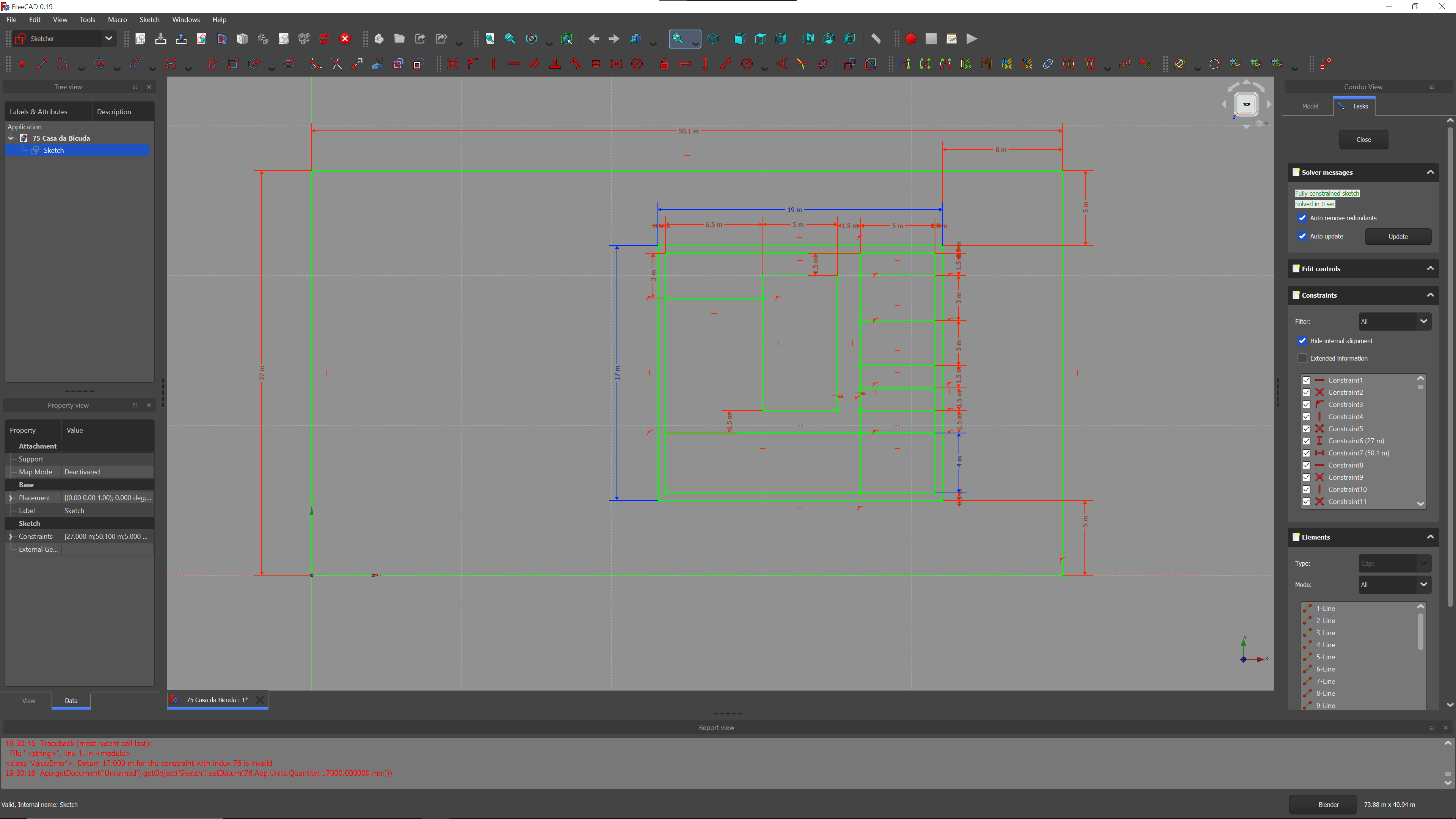
I´ll also attach the FreeCAD file, which only has the base FreeCAD sketch that I will use as a base for modeling. My idea was to use this FreeCAD Sketch and Topologic methods to model it from the start. I was asking if we could apply Topologic to the base FreeCAD Sketch, without even extruding any shape, we could probably have the most interesting way of modeling based on Topologic rules only and a parametric Sketch.
The file is attached and the FreeCAD sketch looks like this with all the parametric base geometry already set:


Comments
@arquitextonica
What you might not have realized about Freecad is that it's Sketches are parametric geometries that are the foundation for a Freecad model. Change the parametric relationships between a sketch and all the model changes accordingly. It's way more powerful than a set of 2D polylines. It's an incredible methodology. Having sketches have a meaning and having topologic build everything else beyond sketches, based on that meaning, would be amazing.
@brunopostle
I think it's very interesting to think on a tool to develop standard architecture in a zip if that's what you're aiming for. However, topologic allows for much more and what's brilliant about the future is how we can free ourselves from constraints. When all software is capable of creating standard architecture with 2 clicks of the mouse, what will matter is creativity and the freedom that software will allow the human mind. I'm interested in that and I'm afraid of making the standard way of doing things too easy, as it might result in the production of the average. Your work is amazing but I would love to see it with a wider scope. If Topologic allows it, why not?
I try to imagine, not sure I understand how to move forward :)
Say, below layout, 6 edges ( 3 'vertical', 3 'horizontal'). It defines 4 areas.
I can't figure out the algorithm to find out the 4 areas automatically. Currently, I need to do that manually - i.e. pointing out which 4 edges define an area and need to do that 4 times :(
This is a very easy workflow for Topologic. Feed the edges into a Cluster, self-merge it, and feed it to wire-cycles with maximum 4 vertices (this is a custom node written in pure python available on TopologicDynamo. Planning to port it to Blender/sverchok. It will return 4 closed wires.
I do not know Revit, Rhino, GH etc. except AutoCAD probably upto 2008, and recently FreeCAD (on Fedora linux) :D
I am trying to understand the capabilities of Topologic, and see if and how the worflow in FreeCAD / daily Architect design development could fit in. Maybe you can show more what you are doing to demonstrate your idea ? Thanks in advance.
BTW, there is an software called TAD which seem have similar concept - Room/ Space as fundamental building block of design development.
@paullee Since you are on Linux you can download and install topologicPy from http://github.com/wassimj/topologicPy
Then you have five options:
1. Use pure python scripts from the console to read and write BREP objects (100% compatible with FreeCAD)
2. Use python scripts within FreeCAD
3. Use python scripts within Blender
4. Use sverchok Topologic visual nodes in Blender (coming soon)
5. Same as #4 but integrate with FreeCAD sverchok nodes.
This is what you will be able to do with Topologic Sverchok nodes or the equivalent. The tool I have in mind needs to go further and, as I said, 'anything-goes-in-free-jazz-architecture' imposes some severe constraints.
@paullee basically, you get the line equation for each of the edges, and with this you can determine which of the other nodes are 'above' or 'below' the line. But if you are coding this in python, Topologic exists to solve these sort of problems for you.
Sounds great :D Need to tell Topologic the numbers of vertices say 4 to form an area ?
@paullee 4 is to limit the search. As you can imagine your diagram can have many sub-shapes. But if you don’t want to do that, you can extrude the lines up to faces, then call CellComplex.ByFaces then call CellComplex.Cells and it will automatically give you four cells. If you want the floor, just extract the face that has a face normal with Z less than 0 (usually -1).
@paullee Here is how it would look in Topologic. Read the graph from left to right. It generates 6 lines as you specified, it makes them into a Cluster, then self-merges the Cluster yielding a Wire then fed into Wire.Cycles to detect closed cycles of maximum number of vertices (in this case 4) and then convert into faces and geometry to display. At the end I move them apart so you can see them.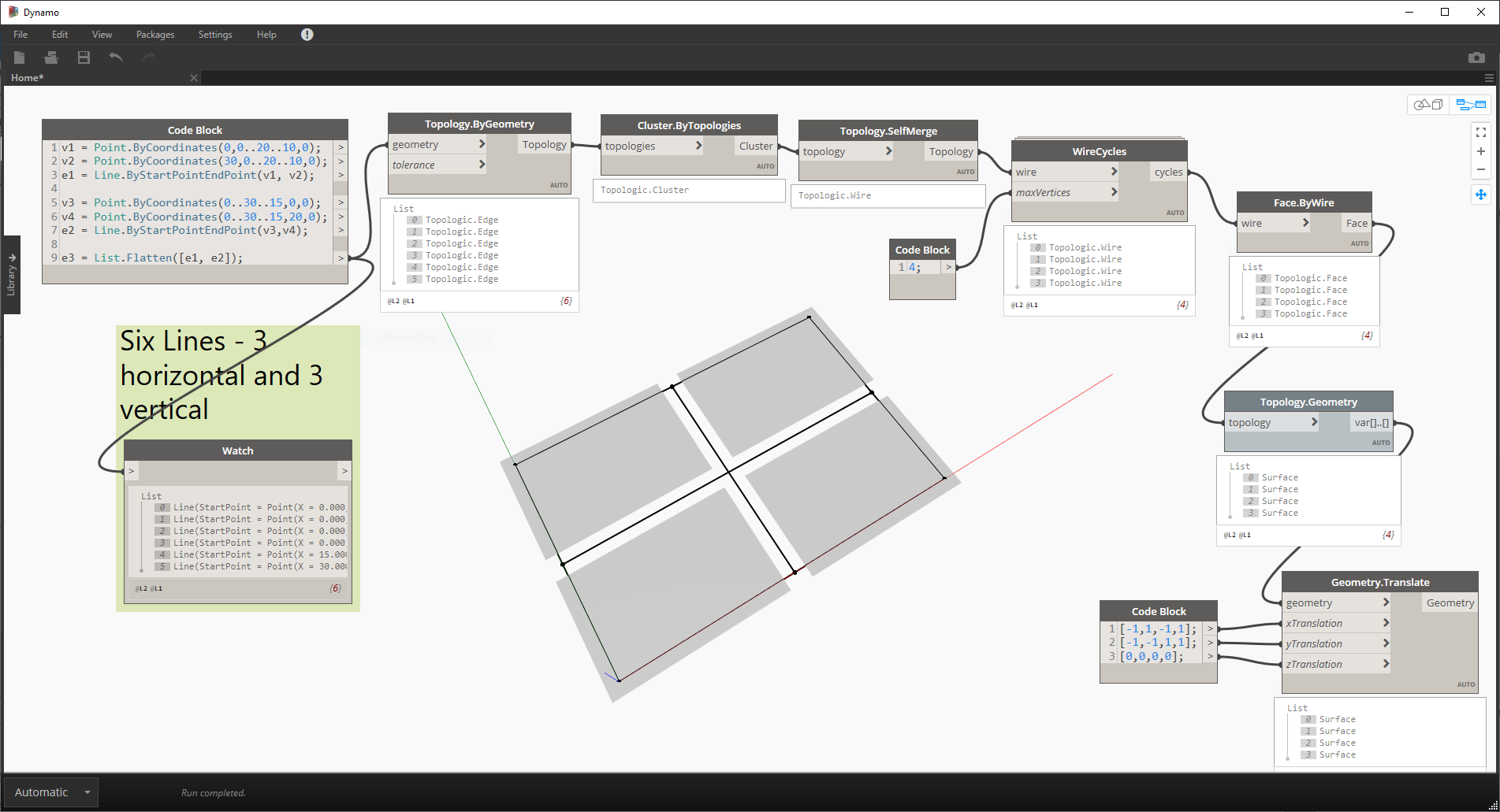
I wonder if Topologic will be able to read FreeCAD sketches. They are not actual geometry, they are only geometric rulers/constraints... I might be wrong.
I am not sure. Topologic can read BREP files. If you send me a sample file, I have FreeCAD and can test it.
@JQL @topologic Seems better idea than I attempt to compile Topologic without much experience in this :D
Seems FreeCAD file *.FCStd is not accepted, I just rename the extension to *.zip for uploading - pls rename back to *.FCStd
Ok, there is a Sketch object, with 6 edges.
Then, make extrude to make 6 vertical faces, 1 bottom face and 1 top face from the edges - all in a Group folder.
p.s.
Maybe this file is better.
There is an Edges Group folder. All the edges in the original Sketch are made into individual Part Shape, if you may have problem to work with the Sketch Object :D
Thanks in advance !
(remember to rename the attached FC file into *.FCStd to open)
@paullee This was quite easy for Topologic in FreeCAD. Mainly, first make sure the 8 surfaces are selected and then paste the following python code:
You get the four Cells converted into four new Parts
Gorgeous !
Hope can use that right in my FreeCAD :D
1 Question at the moment - can you relate back to which 4 (or 6 faces) in FreeCAD shapes each of the generated Cells came from ?
Thanks.
I selected Shape --> Shape007 and then pasted the python script in the python console. It creates Shape008, Shape009, Shape010, and Shape011 automatically from the original 8 Faces.
If you are on Linux, try to follow the instructions on github.com/wassimj/topologicPy and if you have FreeCAD 0.19 daily, it should work. The tricky part is always installing cppyy and all its dependencies, but I think the recipe I have on github is good. Myself, Theo Dounas and @brunopostle have been able to install Topologic and cppyy on Linux and it works great. My setup is python 3.8, Ubuntu 2.10 Groovy Gorilla and FreeCAD 0.19 daily build.
Oh sorry. I did not understand your question! You mean to go back to the original faces. This would be a geometric workflow of testing if the two faces are co-planar and identical etc.. For simple cases, you can compare their centroids and that might be enough perhaps (if the original face was not cut up into smaller pieces). In principle, it is possible like this:
1. For each Cell in the result:
2.----For each face in the Cell:
3. -------- Get a vertex guaranteed to be inside (Face.InternalVertex())
4. ------------ For each face in the original list:
5. ----------------Is the internal vertex inside the original face in question?
6. -------------------- If so, copy attributes from that original face to the cell face.
This would be a very useful feature, for the elements of the cell complex to inherit any attributes (as a dictionary) of the original objects.
It is certainly possible. I had done that in Dynamo many months ago.
Hi @brunopostle Here it is :). I didn't bother with dictionaries, but the principle is the same. The 20 derived faces are checked against the original 8 faces. If they match, the name and the color is transferred to the new face. If you look closely and count, you will notice that 2 of the original faces (top and bottom Shape and Shape007) yield 4 new faces while the other faces yielded 2 new faces.
Thanks taking the time to explain :D This is exactly what I mean.
Though I thought it do not require the user to test by going through the loop you indicates ? During the process Topologic identify the 4 resultant Cells, would it already know which 6 Original Faces creates that 'boundary' ?
It is apparent to a human being, 2D on the Sketch or 3D of the 8 Faces - that's the algorithm to find the 4 'boundaries' in 2D Sketch I would like to know - the same feature in AutoCAD to do Hatch / find boundary ?
Not only as @brunopostle point out that attributes can inherit, but the Original Edges and the Resultant Cells / Faces can 'co-relate' to each other. For example, user may do a script to ask Topologic to deduce what faces are External, then assign back desirable materials / thickness / reflectance to the Original Faces / Edges (Wall / Curtain Wall ) and the elements it contain (Window / Spandrels / Cladding / Insulation).
Just some random thoughts :)
Hi @paullee, There isn't a way to relate the faces without a search. The subdivision of an orginal face to create the faces of the cellComplex is buried deep in opencascade's engine, so we need to do this after (not during) the creation of a CellComplex from a list of Faces.
What you write in the last message is exactly correct: Now that we have built the CellComplex, we can ask questions such as:
1. For a given Cell in a CellComplex, give me the list of its adjacent Cells?
2. For a given Face in a CellComplex, give me the two Cells that it separates (or one Cell if it happens to be an exterior Face).
3. For a given CellComplex, give me the outer faces and the inner faces in separate lists (you can further divide by vertical vs. horizontal)
4. For a given Face, give me the apertures and other contents that it may contain.
The above are just examples. We can think up other more advanced queries that can be readily answered by Topologic. For example, for a given Cell in a CellComplex, how central or how isolated is it?
Thanks, I can partly understand the mechanism when you mention underlying process is done by OCC :D Just curious what the algorithm do ?
I do not know much about OCC, it is the core of Part WB in FreeCAD to my understanding. I see there are methods (exposed in python too) like childShapes(), isSame(), isEqual() that may help to trace the history of OCC operation. The method to check the correlation become significant if the workflow start with an Object in FreeCAD, rather than starting from Topologic, I think ...
And maybe Topologic can find the escape path in a labyrinth ? :D
@paullee The workflow I demonstrated does start with FreeCAD objects and returns FreeCAD objects. Anyway this is how it can be done in Topologic, but if someone can hack OCCT that would be impressive (OCCT is notoriously difficult and low level), but I doubt that is the right way to do it when you can write it easily in a few lines of code. That’s why people use libraries: to work at a higher level.
Thanks @topologic, I understand! Impressed very much by the capabilities of Topologic. Would try the codes you shows when I manage to compile and run it here :D
So if it can run in and sort out a maze (labirynth) , then topologic can 'reanalyse' any IFC ? and redefine it, and correct what was wrong. The (imperfect) IFC -tree (graph) is then replaced by the Topologic-tree, which of course can be rewritten as IFC.. the IFC-correction-tool ? The import/export tool for all BIM authoring softwares.. depending on the dictionnary settings..
I don’t know enough about ‘problematic’ IFC to know if Topologic can correct them, but happy to collaborate and test.
Are you on fedora Linux? I have built rpm packages of all the Topologic dependencies (except for topologicPy itself, but this is the easy one). Currently f32, f33 & f34, but I can probably push f31 too.
Thanks! Yes, but still unfortunately on f31, no time to move ( to f33 probably) yet ...
Hi @topologic and @paullee
It seems I have a lot of reading to do as the discussion has bumped since you asked the model and paullee responded much faster than I did.
I have come up with a file for an actual project I'm just starting to model.
So I might as well show you the original hand sketch (which is not made in FreeCAD of course):
I´ll also attach the FreeCAD file, which only has the base FreeCAD sketch that I will use as a base for modeling. My idea was to use this FreeCAD Sketch and Topologic methods to model it from the start. I was asking if we could apply Topologic to the base FreeCAD Sketch, without even extruding any shape, we could probably have the most interesting way of modeling based on Topologic rules only and a parametric Sketch.
The file is attached and the FreeCAD sketch looks like this with all the parametric base geometry already set: