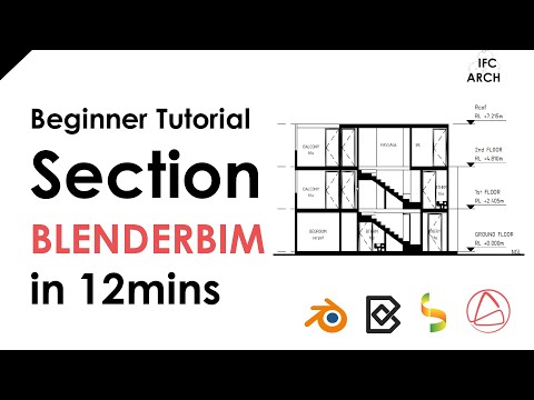
[BlenderBIM] - Beginner Tutorial - Section in 12mins

AceAce
edited March 8 in General

This thread is to discuss this video tutorial:

You can download the files below:

brunopostleNigelCoenMoultvictorklixtobitacovirdimitar

Comments

  • edited March 8

    @Ace Thanks for another awesome video!
    Why not put the door swing in the Model/Annotation/SECTION_VIEW representation of the door type?
    video: https://www.dropbox.com/s/l0pwefa6sacdpxs/2023-03-08_08-47-36_Blender_blender.mp4?dl=0

    Ace
  • Because I did not think to do it in the model haha, awesome suggestion!

  • Hey @Moult you mentioned the dxf export command in the video comments

    I've tried to input it, but I'm not certain how to activate it after? Is there maybe another setting that needs to be adjusted after printing

  • Assuming it's input correctly (e.g. you have those commands in your path like inkscape and pstoedit and you use the square brackets), I think it runs on the Create Sheets button. This was a feature from waaaaay ages back when I Had To Get Drawings Out The Very Next Day Whilst Building Drafting Features so no idea if it still works :)

    Ace
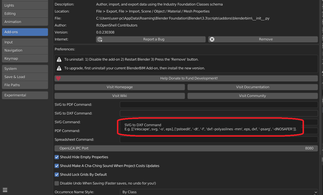
  • Ah awesome, I've put in the command as the example:
    [['inkscape', svg, '-o', eps], ['pstoedit', '-dt', '-f', 'dxf:-polyaslines -mm', eps, dxf, '-psarg', '-dNOSAFER']]

    And it seems to hit me with this error:
    Python: Traceback (most recent call last):
    File "C:\Users\USER\AppData\Roaming\Blender Foundation\Blender\3.3\scripts\addons\blenderbim\bim\module\drawing\operator.py", line 795, in execute
    subprocess.run(command)
    File "D:\Blender\Blender Versions\stable\blender-3.3.3+lts.8d94aeb604fa\3.3\python\lib\subprocess.py", line 503, in run
    with Popen(*popenargs, **kwargs) as process:
    File "D:\Blender\Blender Versions\stable\blender-3.3.3+lts.8d94aeb604fa\3.3\python\lib\subprocess.py", line 971, in __init__
    self._execute_child(args, executable, preexec_fn, close_fds,
    File "D:\Blender\Blender Versions\stable\blender-3.3.3+lts.8d94aeb604fa\3.3\python\lib\subprocess.py", line 1440, in _execute_child
    hp, ht, pid, tid = _winapi.CreateProcess(executable, args,
    FileNotFoundError: [WinError 2] The system cannot find the file specified

    Should I pop as issue on the github?

  • edited March 9

    Do you have inkscape and pstoedit in your path? These are external programs not bundled with the BlenderBIM Add-on. On Windows check your system PATH (https://www.maketecheasier.com/what-is-the-windows-path/) and make sure in a command prompt you can type "inkscape" (or "inkscape.exe" on Windows?) and Inkscape should launch. Same with pstoedit.

    Ace
  • Hi guys, how can I configure the section to ignore the body representation of an object and show only the section_view representation? Is that possible? In my case, I have a roof that is modeled as a box, but I would like to show only the tiles in the section drawing. I have successfully created the tiles as lines in the section_view representation, but the body representation is showing and overlaps it. In the image below, I placed the tiles a little higher just to see if it was working.

  • can you share the file?

  • Yes, here it is:

  • I tried to add Plan/Body/SECTION_VIEW context but couldn't get it to work. Although I feel it should. Think there might be a glitch.
    I was able, however, to get Model/Body/SECTION_VIEW context to work, see video here:
    https://www.dropbox.com/s/1bseirq8v0e79qs/2023-03-31_15-27-20_Blender_blender.mp4?dl=0

  • This is the way it is in a typical door...
    If there's a Plan/Body/PLAN_VIEW context it doesn't show the stuff in the Model/Body/MODEL_VIEW context if the target view of the drawing is PLAN_VIEW... or so i think it works this way. :)

  • Thanks! So I guess we should use annotation when we want to add something but preserve the body representation, like you did with the door swing. Is that correct?

  • i'm not 100% certain... contexts confuse me a little, still.

  • Using Model/Body/SECTION_VIEW is correct. Plan/Body/SECTION_VIEW doesn't work because it is a plan view (i.e. no Z axis) whereas you are in a section view.

    The behaviour of contexts has changed a bit over time (and this is uncharted territory so we are still feeling our way through to figure out what works for all scenarios). I apologise for the confusion, hopefully this will clear it up.

    A context (or specifically, a subcontext, you never use contexts directly) is made of 3 major categories:

    • ContextType (Model/Plan): Model indicates it stores 3D geometry using XYZ coordinates. Plan indicates it stores 2D geometry using XY coordinates only. Note that these are not global XYZ, these are local XYZ coordinates relative to the orientation of the object (i.e. the orange dot). So if the object is rotated, 2D XY may not be pointing exactly up.
    • ContextIdentifier (Body/Annotation/Axis/Box/etc): we'll focus on 2 here. The Body says that the geometry represents the body of the object. The Annotation says that the geometry further annotates (e.g. highlights/labels/directs attention to a particular aspect of the element) the element. So if you are drawing a plan view of a door where the door panel is wide open, that is part of the Body. However, the door swing arc in theory is an Annotation, as it merely annotates the clear extents of the swing and directionality. Similarly, the triangle symbol / arrows used for awning and sliding windows are Annotations. In your example, your geometry is of the roof tiles, which is the Body.
    • TargetView (MODEL_VIEW/PLAN_VIEW/SECTION_VIEW/etc): this indicates that the geometry is suited towards this particular type of view and should take priority.

    (note there is also TargetScale but we don't yet support that, it's pretty self explanatory though, such as different levels of detail for different scales).

    In drafting, we always draw the body of the object, and then draw the annotation in addition to the body. (e.g. first you draw the window, then you draw the arrow indicating the sliding direction of the window). There are additional rules that certain values are special in that they often use particular 2D symbology that is unique to those views that you won't typically find elsewhere (e.g. fire extinguishers have a symbol on a plan, but you'll never use that symbol in a section).

    So for a given drawing, here are the rules followed:

    1. First the Body ContextIdentifier is drawn. Then, the Annotation ContextIdentifier is drawn in addition.
    2. If there are multiple Bodies and Annotations to choose from, the one with a TargetView that matches the drawing is prioritised. The MODEL_VIEW TargetView is the fallback.
    3. In addition, we have a special rule that if the drawing has a PLAN_VIEW or REFLECTED_PLAN_VIEW, the Plan ContextType is prioritised over Model.

    Let's see a real life example. Let's imagine we are doing a regular floor plan drawing (i.e. PLAN_VIEW). If we had all possible Body permutations in theory, this is the priority list:

    1. Plan/Body/PLAN_VIEW (top priority, as you'd expect)
    2. Plan/Body/MODEL_VIEW (fallback)
    3. Model/Body/PLAN_VIEW (fallback again)
    4. Model/Body/MODEL_VIEW (final fallback)

    Same goes for Annotations, just replace "Body" with "Annotation". Here's another example for a section (i.e. SECTION_VIEW):

    1. Model/Body/SECTION_VIEW (top priority)
    2. Model/Body/MODEL_VIEW (final fallback)

    Notice we never consider 2D things in a section view. There are a number of problems with 2D in sections and elevations that has led to this special third rule.

    Acetheoryshawbruno_perdigao
  • Thanks for the explanation, it's much clearer now

Sign In or Register to comment.