

Real World Examples or Project Spatial Breakdown

I am trying to get my head around the whole IFC spatial structure hierarchy and apply it to a real world application, and more specifically for the new IFC4.3. Moving forward, I would suspect if clients are requesting IFC deliverables, as part of their responsibility or a BIM Consultant that represents their interests needs to provide the project spatial structure breakdown. I would also suggest these needs to be done as 1 of the initial conceptual design steps.
Project Type: IfcBridge
Project (IfcProject): Queensland TMR (Bridges)
Site (IfcSite): North Coast, Wide Bay & Burnett
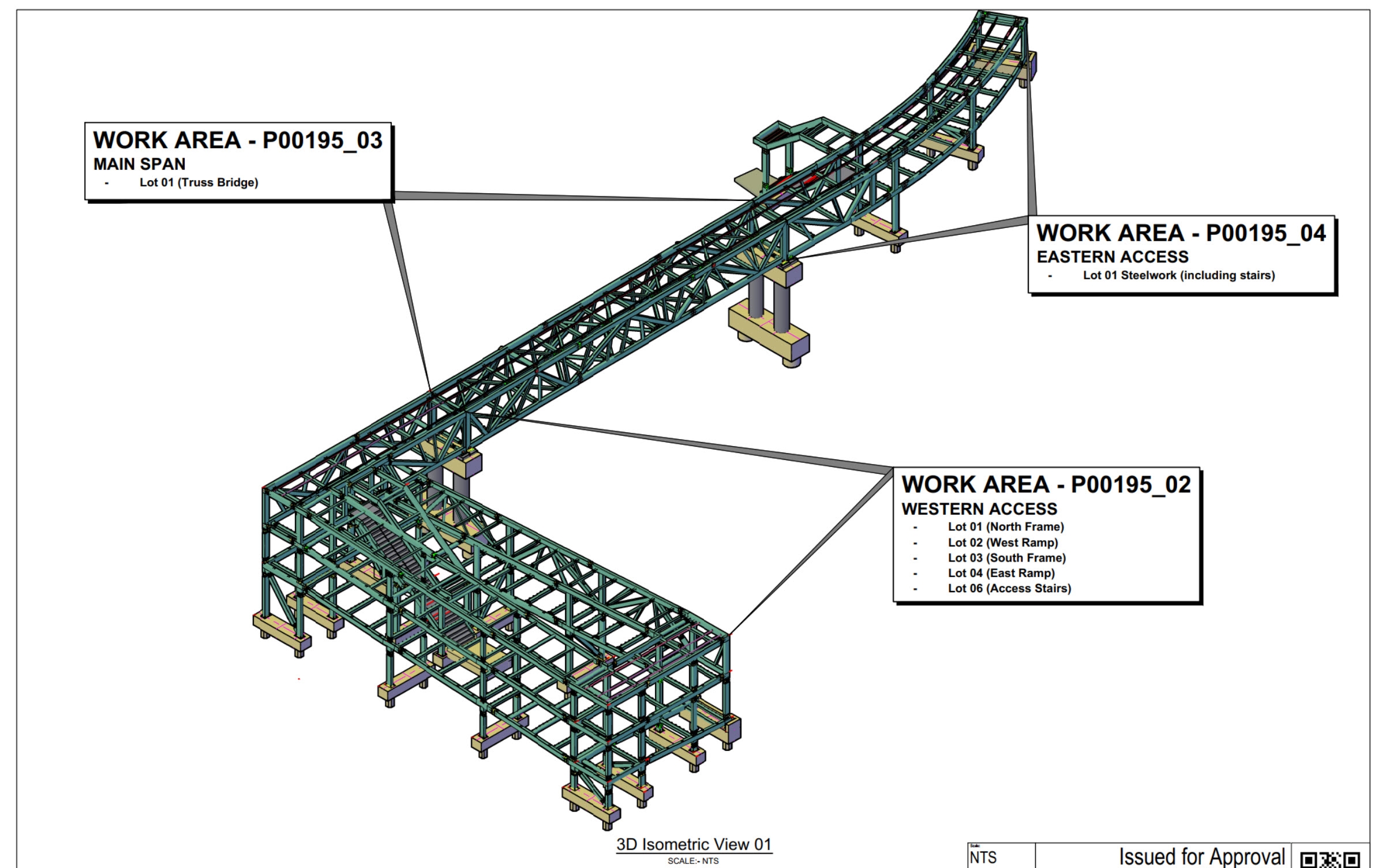
Location (IfcFacility): Elizabeth Avenue Pedestrian Overpass
Structure (IfcBridge): Proposed Steel Pedestrian Bridge
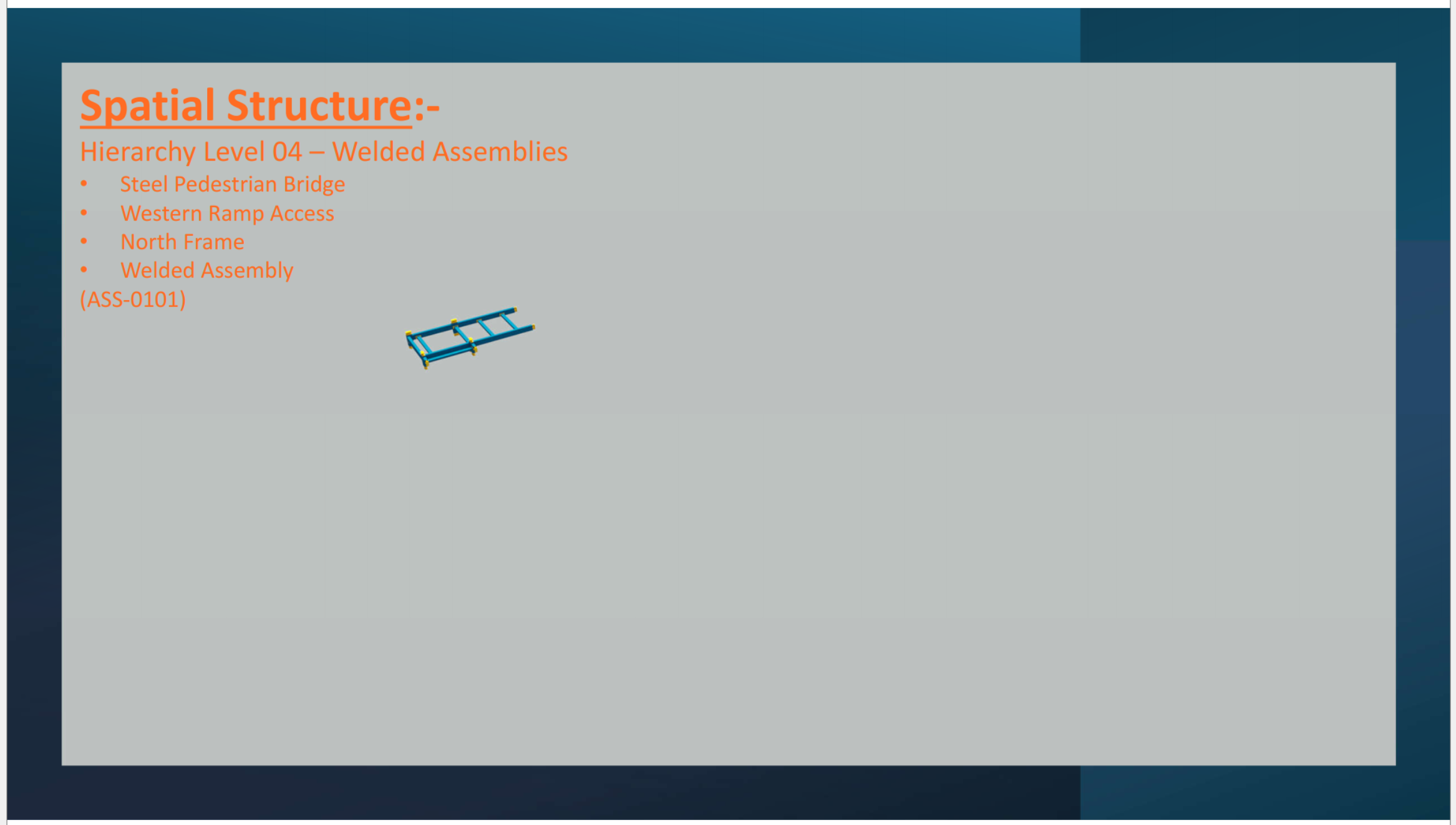
Work Area / Level (IfcBridgePart): Western Access Ramp
Work Zone (IfcSpace): North Frame
I would be interested in the thoughts of others how spatial structure should be applied.


Comments
Hi,
I'm also playing around that. :)
I think that:
1) Work Zone (IfcSpace) --> Work Zone(IfcSpatialZone)
as suggested by IFC Spatial Zone – Use Cases, Requirements and Implementation in buildingSMART Technical Reports
2) the lot's I would classify as IfcElementAssemblyType or If IfcElementAssembly aggregated in IfcBridgepart
I was thinking my Welded Assemblies would be where I should be using the IfcElementAssemblyType. Would that be right or is that 1 level too late?
It seems correct :)
I agree.
Another option could be:
Work Area / Level (IfcBridgePart): Western Access --> CompositionType = COMPLEX
Lot 01 / Level (IfcBridgePart) : North Frame --> CompositionType = ELEMENT (aggregated in Work Area)
But this may just be adding unnecessary complexity...