Maybe not a popular answer but to make more progress in having something like a family editor in Revit and anything else that's needed for creating user made types/families. I know others have different workflows that don't need this, but I dream heavily of using BonsaiBIM to replace Revit at my workplace but my engineering work revolves a lot around making many custom families for different connections we use in precast concrete.
I have also two request! But one is for FreeCAD: rebar. I hope reinforcement workbench will be integrated in IFC and restarts its developement.
For Bonsai i will like a tool able to enlight the free surface of intersecting concrete element (like clash detection) in order to obtain the costing of formwork
@theoryshaw oh, Sorry, you are right, I'll stay with drawing documentation improvement! I was using Bonsai a lot yesterday and i guess i got carried away...
@carlopav no worries! :) Basically asked for (1) since it better signals what's really important to users--and what contributors/developers might want to prioritize.
Regardless, however, any feature requests listed here (or any more that anyone has in mind), i highly recommend adding the request on the github issue tracker here: https://github.com/IfcOpenShell/IfcOpenShell/issues
Ok, two outright ;) More drawings support, and better tie-in with other blender modeling tools, especially modifiers and geometry nodes. I know that it is its own independent IFC authoring tool on top of Blender's UI, but to me it's missing a point to try to reinvent so many things that work so well in Blender, which could somehow be "baked" under the hood for IFC.
When creating a new IFCType under Type Templet – “Vertical Layer” that the new IFCType does not default into a 1000x1000mm square but to dimensions given to the IFCType. (The vertical layer default dimensions should be dimensions of the 1st saved Element)
For example: -
I would like to create an IFCType “Covering-Ceiling-Gyprock 1200x900x4mm” as a “Vertical Layer” because the thickness of these boards doesn’t change.
When adding the type I don’t want to edit the geometry every time from a 1000x1000 square to a 1200x900 square and then duplicate the element. I only want to edit the geometry of the IFCType “Covering-Ceiling-Gyprock 1200x900x4mm” when it is not 1200x900 (cut a piece off). This will then tell me how many 1200x900 boards.
Using “Custom mesh” is another option but it is not so straight forward to edit the dimensions when you need to cut a section off, or is the correct way to add a void on the elements you want to “cut”?
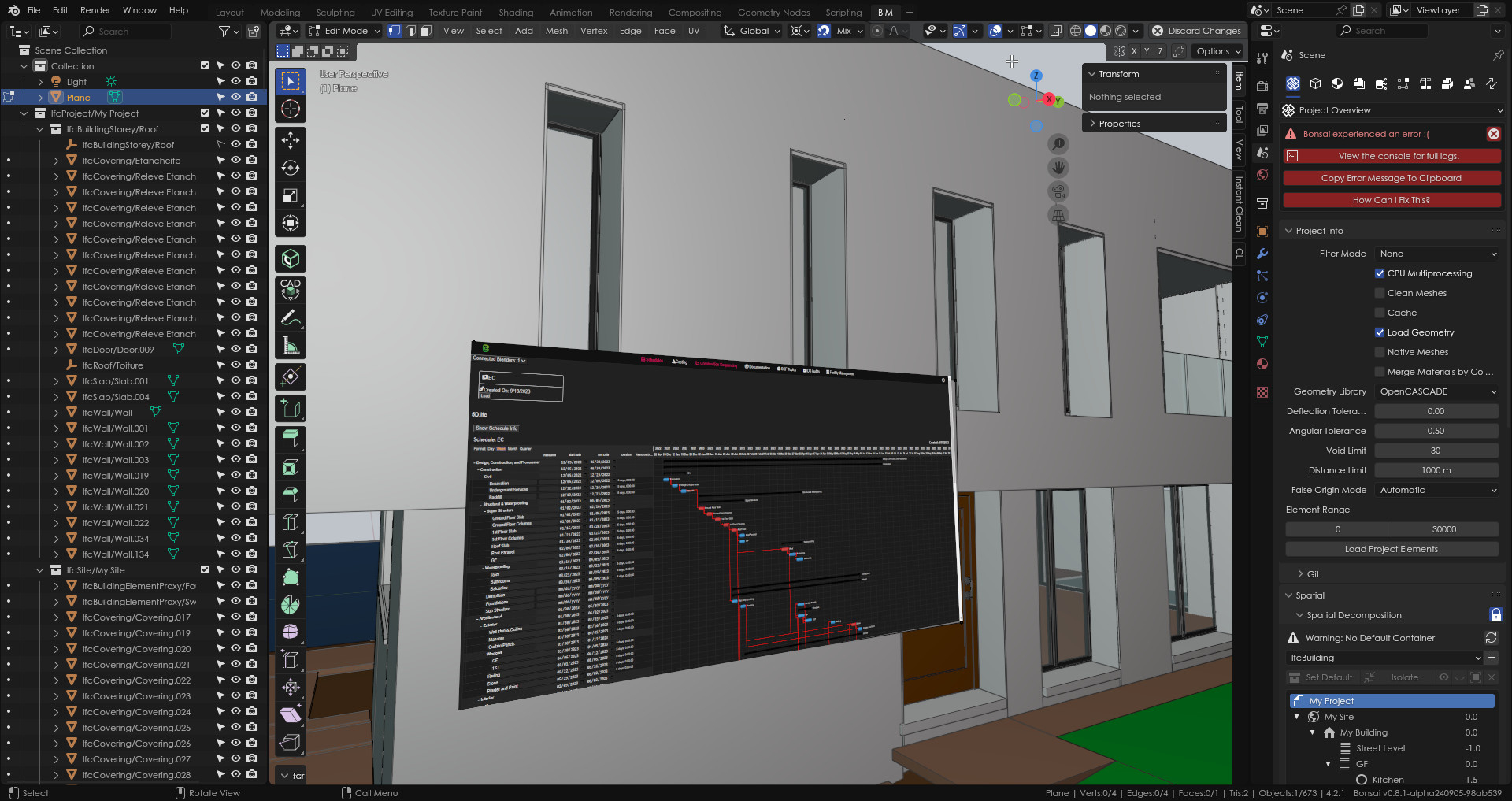
Bonsai now prints non-ifc objects.
That cube to the left is non-ifc. GIFs flip between Freestyle and OpenCASCADE modes, one with Underlay, and one without...
styling, however, is not possible--notice dashed line goes missing with Freestyle.
I think it could be useful to have a Z offset value field, similar to Angle to adjust the one set in the container, something like:
for instance: my walls usually start from the top of the concrete slab, typically 5 or 10 cm below the FFL (Finish Floor Level) = 0.00 I would assign to the same floor container, starter columns start from atop the plinths, etc..
having containers and levels tied together is OK but could be limiting in some situations, the Z offset might be a simple workaround?
Interesting @steverugi, there's at least two scenarios whether your buildingstorey corresponds to structural slab or finished floor level. Perhaps the offset should be a common property: ElevationOfSSLRelative or ElevationOfFFLRelative.
Hi @steverugi, if I'm not mistaken, this feature already exists:
>
yes, but I thought a more generic Z-offset applicabe to other elements like columns, beams, and slabs would have been useful
or the same RL as already available for walls, windows, doors
cheers


Comments
Maybe not a popular answer but to make more progress in having something like a family editor in Revit and anything else that's needed for creating user made types/families. I know others have different workflows that don't need this, but I dream heavily of using BonsaiBIM to replace Revit at my workplace but my engineering work revolves a lot around making many custom families for different connections we use in precast concrete.
Oh, there are another 2 things in my dream book:
I'll throw one in...
visualising layered walls/slab/etc from IfcMaterialLayerSets
@carlopav was that (3) requests? ;)
I have also two request! But one is for FreeCAD: rebar. I hope reinforcement workbench will be integrated in IFC and restarts its developement.
For Bonsai i will like a tool able to enlight the free surface of intersecting concrete element (like clash detection) in order to obtain the costing of formwork
@theoryshaw oh, Sorry, you are right, I'll stay with drawing documentation improvement! I was using Bonsai a lot yesterday and i guess i got carried away...
@carlopav no worries! :) Basically asked for (1) since it better signals what's really important to users--and what contributors/developers might want to prioritize.
Regardless, however, any feature requests listed here (or any more that anyone has in mind), i highly recommend adding the request on the github issue tracker here: https://github.com/IfcOpenShell/IfcOpenShell/issues
Ok, two outright ;) More drawings support, and better tie-in with other blender modeling tools, especially modifiers and geometry nodes. I know that it is its own independent IFC authoring tool on top of Blender's UI, but to me it's missing a point to try to reinvent so many things that work so well in Blender, which could somehow be "baked" under the hood for IFC.
Is it still going?
I would love to see the implementation of IfcRelDefinesByObject in Bonsai.
When creating a new IFCType under Type Templet – “Vertical Layer” that the new IFCType does not default into a 1000x1000mm square but to dimensions given to the IFCType. (The vertical layer default dimensions should be dimensions of the 1st saved Element)
For example: -
I would like to create an IFCType “Covering-Ceiling-Gyprock 1200x900x4mm” as a “Vertical Layer” because the thickness of these boards doesn’t change.
When adding the type I don’t want to edit the geometry every time from a 1000x1000 square to a 1200x900 square and then duplicate the element. I only want to edit the geometry of the IFCType “Covering-Ceiling-Gyprock 1200x900x4mm” when it is not 1200x900 (cut a piece off). This will then tell me how many 1200x900 boards.
Using “Custom mesh” is another option but it is not so straight forward to edit the dimensions when you need to cut a section off, or is the correct way to add a void on the elements you want to “cut”?
@dimitar
Bonsai now prints non-ifc objects.
That cube to the left is non-ifc. GIFs flip between
FreestyleandOpenCASCADEmodes, one with Underlay, and one without...styling, however, is not possible--notice dashed line goes missing with
Freestyle.Just thinking outside the box, in order to achieve a WYSIWYG interface, could you bring in and superimpose a live, continuously updated SVG, as a overlay to the drawing?
This got me thinking: https://community.osarch.org/uploads/editor/58/kare85wcqszv.mp4
maybe streaming a browser inside Blender?
https://chatgpt.com/share/c9d35ab1-5bfc-4783-a60e-dc65819df490
Could stream and edit spreadsheets, gantt charts, etc as well, 'in world'.
Mockup:
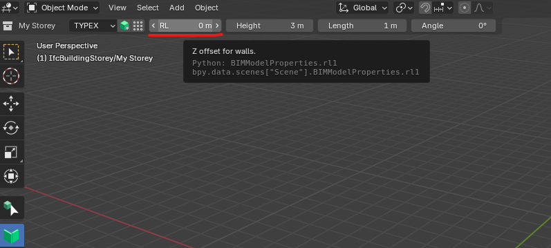
Z Offset value
I think it could be useful to have a
Z offsetvalue field, similar toAngleto adjust the one set in the container, something like:for instance: my walls usually start from the top of the concrete slab, typically 5 or 10 cm below the FFL (Finish Floor Level) = 0.00 I would assign to the same floor container, starter columns start from atop the plinths, etc..
having containers and levels tied together is OK but could be limiting in some situations, the Z offset might be a simple workaround?
Interesting @steverugi, there's at least two scenarios whether your buildingstorey corresponds to structural slab or finished floor level. Perhaps the offset should be a common property: ElevationOfSSLRelative or ElevationOfFFLRelative.
yes, as illustrated in the relevant page
https://standards.buildingsmart.org/IFC/RELEASE/IFC4_3/HTML/lexical/IfcBuildingStorey.htm
in my modeling workflow this Z-offset feature would be very useful when creating/inserting elements at a particular elevation value, thanks
Hi @steverugi, if I'm not mistaken, this feature already exists:
I'm not able to open this link.
hi @bruno_perdigao
>
yes, but I thought a more generic Z-offset applicabe to other elements like columns, beams, and slabs would have been useful
or the same
RLas already available for walls, windows, doorscheers
sorry, was behind a Linkedin group...
here it is...