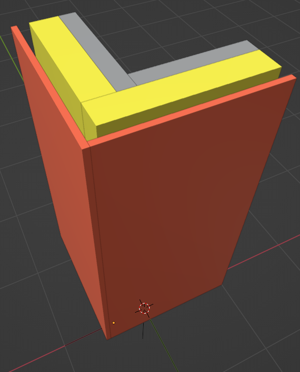
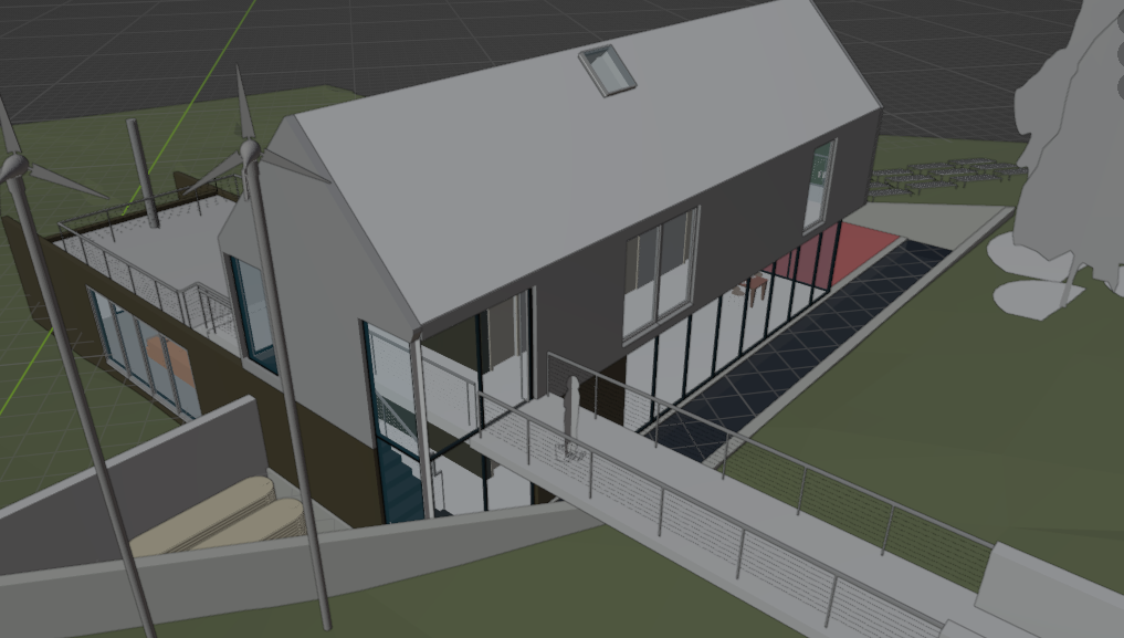
I am a bit confused how BIMVision decides which colour to show, I have modelled this in BlenderBIM:
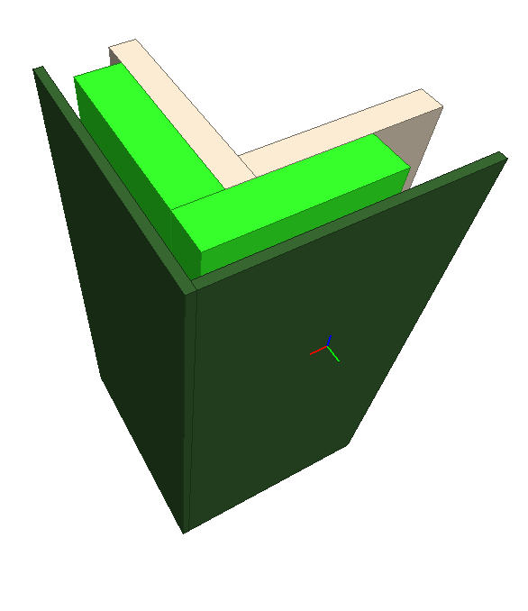
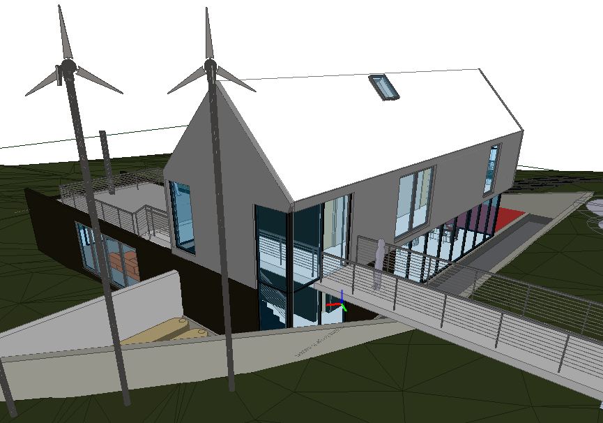
Loading it into BIM Vision it decided to make everything green
But with a IFC made from Revit or Archicad BIM Vision seems to have no problem with the colours.
Do I need to do something in BlenderBIM to assign a style? Because I use a batch generated demo library.
I think it uses the Ifcstyle to set the colour?
So you need to set the colour here:
And select 'update style colours'
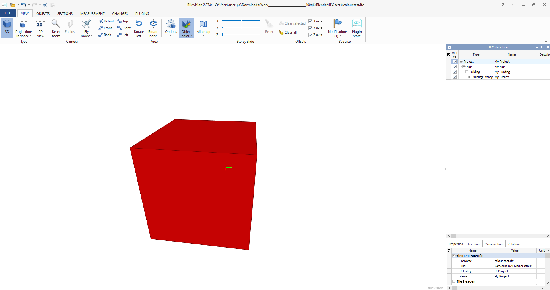
And it will reflect in Bimvision:
I dont know how to do that automated though sorry
Ok I think I have got it, somehow, Bimvision is also picking up the Ifcmaterial colour (from Blender) and the Ifcstyle colour and mixing/multiplying them?
So if you ONLY set the IfcStyle colour it works perfectly:
I couldn't fix you materials so I just set some new ones (and the one insulation wall has the original material which I cant remove for some reason so it's still wrong but the principle is still there
So dont set the IfcMaterial colour, just do the IfcStyle colour
@theoryshaw said:
nice! good to know.
The UI is begging for this to be under the 'IFC Style' panel.
Ya, i think since the viewport display is already there @Moult didn't duplicate it, but it should definitely be under Ifc Style labeled 'IfcStyle colour'
same problem here sometimes ...
In Nemetschek Allplan one only can define one color for a object. In Ifc a object has two colors the representation color and the material color. Nemetschek Allplan and AFAIK Nemetschek Vectorworks as well do write sometimes different colors for representation and material ... In FreeCAD I implemented a warning if they differ. There is even a third color. If a viewer has problems to read a color at all in most cases the viewer uses grey, but most material used in my models is concrete and concrete is grey. Thus sometimes one might think everything is ok, but it is grey because nothing is ok. ...
Colors in ifc are terrible ...
BimCollabZoom (Free use of "smartviews" with color coding and BCF). Their add-ons in proprietary software like Revit works well too.
BIMVision (For measuring, very precise and easy to use measuring of geometry)
all 100 computers in the company I work in do have these both installed for exactly the reason you mentioned :-) (except the Revit stuff. We do not use Autodesk software)
on my one is in addition BlenderBIM, FreeCAD, IfcQuery and Solibri installed
While I think Solibri does all kind of things to make the "free" version unattractive
by adding all kind of hurdles ... I gave up a few years ago.
But maybe that has changed in recent years.
@theoryshaw said:
nice! good to know.
The UI is begging for this to be under the 'IFC Style' panel.
Ya, i think since the viewport display is already there @Moult didn't duplicate it, but it should definitely be under Ifc Style labeled 'IfcStyle colour'
There are quite a few misunderstandings around colour in IFC which has led to an incredibly poor user experience, and the way colour is presented also has a lot of confusion. Let me try to clarify how things actually work and hopefully we can brainstorm a good UX solution to clearly describe it (@theoryshaw's PR and @Ace's proposal is only half a solution - but a good starting point).
First, let's define an "IFC Material" as a physical material (i.e. steel, wood, etc) that has no colour or appearance data. Only pure physical properties. In contrast, an "IFC Style" contains appearance data (e.g colours, stroke thickness, fonts, etc) ... and there are different subtypes of IFC Syles: IFC Surface Styles (e.g. the appearance of surfaces, such as polygons or BReps or Solid Surfaces), IFC Curve Styles (e.g. the appearance of 2D curves, lineweights, etc), IFC Text Styles (The appearance of textual annotation / fonts / etc), and I think one more but I don't have the docs open. Given these subtypes you can see why it is logical to separate IFC Materials from IFC Styles, compared to the CG world where material = style (which is not true for IFC). For convenience, let's say IFC Style = IFC Surface Style because that's what we're mostly interested in here.
IFC geometry may have, in order of priority (higher priority overrides lower priority):
An IFC Style associated to the geometry, which gives the geometry's colour. The object may also have an IFC Material associated here, and that IFC Material may or may not have a colour, but it doesn't matter, since direct IFC Style assignment is always the top priority.
An IFC Material associated to the object, and that IFC Material has an IFC Style, which then gives the geometry colour
An IFC Material indirectly associated to the object (e.g. by material inheritance from its type) and that IFC Material has an IFC Style, which then give sthe geometry colour (this is only a minor variation of number 2)
(There is technically another way but nobody uses that other way and it's ridiculous and IFC should probably delete it.) Also note that this is quite similar to how CG can have colours assigned either to objects directly or to object materials, or to objects sharing mesh data or objects not sharing mesh data ... which is quite complex too but I don't hear the CG guys complaining.
So now the question is ... what do we mean by "Colour"? An IFC (Surface) Style can define different types of colour. It can define a "Shading" colour, this is a simple colour that you see in a viewport (like the Blender viewport). It's purely aesthetic and has no other intelligence. This is equivalent to Blender's "Viewport Colour".
Another "Colour" is a "Rendering" colour. This is not just a simple viewport colour, this now can have multiple colours, such as a "Diffuse" component, a "Specular" component, a "Emissive" component, etc all depending on the rules of the Illumination / Lighting rendering engine. In the case of IFC, it follows the rules of glTF/X3D, so the colours (plural!) you specify follow the different lighting models in glTF/X3D. Because Blender is capable of being glTF compatible, this translates to particular Blender material node tree setups (and changing the base colour in the default BDSF node in Blender is effectively changing this colour). However, other IFC viewers like Solibri, BIMVision etc do not have rendering capabilities like Blender. And therefore they almost certainly will not show these "Rendering" colours. Instead, they will only show the simple "Shading" colours described above. This leads to a ton of confusion by users. Which colour is correct? Both! (If both exist) The BlenderBIM Add-on is super unique because we support both because we support rendering!
Then there is another "Colour" called "Texture Colour". These are rendering colours that come from an image texture instead of just a single RGBA value. The image texture may either have a single "bbox stretch mapping" which is very suitable for single image planes for signage and such on buildings, or it may have UV coordinates for the texture mapping. The BlenderBIM Add-on has full support for stretch mapping but only "save" support for UV coordinates (not loading, unfortunately). Like "Render Colours", these follow the X3D 4.0/glTF standards and therefore you can have multiple textures for diffuse, specular, normal, etc components depending on your nominated reflectance method.
There is another type of "Colour" I'll call "Photometric Colour" (IFC has two subtypes for this: Lighting and Refraction). This is the type of colour defined for illuminance and luminance photometrically validated light simulation. As you know, the colours Pixar uses are beautiful, but completely wrong for light simulation (hint: anything pure white or pure black is instantly wrong). Because buildings are physical, IFC supports a "Photometric Colour" too, and this one can be fed into simulation software like Radiance. No IFC viewer will ever show you this colour (not even the BlenderBIM Add-on) because none of them support light simulation (the BlenderBIM Add-on used to show it a long time ago, but the feature was deleted and I need to readd it in a smart way to minimise confusion).
Then there is a final colour known as an "Externally defined style". This is a style that is completely 3rd-party to IFC. IFC recognises that as an ISO standard it will never keep up with the myriad of clever innovations by the CG industry and there will always be interesting shaders by third parties. This effectively lets you delegate the entire shader to an external URI - how that is interpreted is totally arbitrary. We actually used to support this in the UI and support arbitrary Cycles node trees - this is what you might use if you want to support complex Cycles, Renderman, etc shader setups.
In summary: IFC Material != IFC Style. IFC Material has no colour data. IFC Styles had many substyles, but IFC "Surface" Style is the one we're mostly talking about. Colours can be a "Shading Colour", or many "Rendering Colours", "Texture Colours", "Photometric Colours", or "External Colours". You can simultaneously have all 5 colour types defined and use them in different situations.
I hope this explanation has helped. The BlenderBIM Add-on has the most advanced colour and texture support that I know of (except for that other one which does support texture coordinates, but I don't think supports the other rendering parameters) so now the problem is UX: how is this best presented to users to minimise confusion. I like @theoryshaw's start, but it's a start - I'd like to see something that is comprehensive to the nature of IFC Styles.
Anyway I'm on holiday right now so I'll have to delay a closer investigation until I get back.
Ping @bernd@yorik - I also hope FreeCAD (especially with the new Native IFC initiative) can also have top notch IFC style support.
although today,
the differences between vector drawing, CAD, BIM until 3DCC Apps are overlapping quite a bit.
CAD : Object Colors :
Line Colors, Fill Colors, Hatches, (even assigned images or transparencies)
Usually defined by Object Attributes/Properties or by Layer/Classes
They DO influence the Object's appearance
BIM : Materials :
Which i call "Physical Materials"
Which are basically just Data Information in first place
They DO NOT influence the Object's appearance per se
3DCC : Materials :
Which i call "Rendering Materials"
Which can use Colors, Image Textures, Procedurals, .... in all kind of Material channels
Their only purpose IS to influence the Object's visual appearance
If I got right what I read above,
IFC Standards will at least translate : 2. BIM : Materials,
just like any other IFC Tag information.
But I am a bit unsure now what happens in IFC with ,
1. CAD : Object Colors :
Line Colors, Fill Colors, Hatches, (even assigned images or transparencies)
exactly,
or what IFC (4.x ?) supports from : 3. 3DCC : Materials
at all.
While I expect even some discrepancies between IFC standard supported features
and what IFC exporting or IFC Viewing Apps will deliver at the end.
I would not have expected that.
So it is more about checking my BIM CAD's exchange quality and/or
checking IFC in multiple Viewers Apps.
Usually in the past few years I mostly got only 1-2 basic transparent Materials,
if Glass Panes were transparent at all or just partly.
In more recent imports I got mostly all used Materials into CAD back, but not assigned to
any Layer or Object and no useful Materials Settings or even Texture Maps/Paths.
I think I should also check in BlenderBIM to estimate what my IFC exports really contain ....
Apologize for reopening this thread, i did not find an existing thread that might cover my question.
I am teaching my wife, and myself, to use BB a bit more as a couple exerise. We are modeling up our new apartment.
When making a new window resource that should fit in with what we have, i notice whenever i add a new window type, or when activating "Window Parameters", all material colour blanks out when compared to the pre-defined window. I am more than comfortable enough to go into the edit function of the window block and select all faces to reassign some material properties. What i would like to know is if there is a possibility to have for ifc objects predefind ifc materials when adding new typs or changing its parametric values. If every single time you want to make a new window, or change dimensions, and then reassigning new material is a bit of an irritational extra work.
When using the 'parametric window', i don't think it's currently possible to assign individual material to the frame and glazing, if that's what you're asking.
related: https://github.com/IfcOpenShell/IfcOpenShell/issues/2981
What I usually do is to set the modified window as a different type, then I go to edit mode from where I can assign different materials to selected areas of the modified window. Since the original type WT01 has Frame and Glass materials, I use them for convenience.
Thank you Steve for verifying the same methode as I used. It works, though I would assume some where down the line it should be automated with standard values. I see that some of our projects we recive from the architecture firms have well over 20-30 different window resources. I guess currently the only workaround is to premake a costume arc pack and load it in for each new project.
I see that some of our projects we recive from the architecture firms have well over 20-30 different window resources. I guess currently the only workaround is to premake a costume arc pack and load it in for each new project.
I now understad your original post. Indeed a way to separately identify parts within a door or window would be nice to have without entering into their mesh.
However, for basic use applying a frame material to the whole window first, select the glass faces and apply the glass material takes just a few clicks, after that you can use that type in your workflow, but I am relatevily new to Blender and don't know Archipack (it's next on my todo list)
cheers
Comments
I am a bit confused how BIMVision decides which colour to show, I have modelled this in BlenderBIM:
Loading it into BIM Vision it decided to make everything green
But with a IFC made from Revit or Archicad BIM Vision seems to have no problem with the colours.
Do I need to do something in BlenderBIM to assign a style? Because I use a batch generated demo library.
I think it uses the Ifcstyle to set the colour?
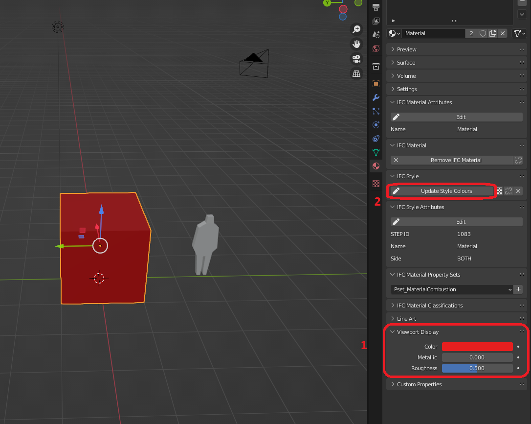
So you need to set the colour here:
And select 'update style colours'
And it will reflect in Bimvision:
I dont know how to do that automated though sorry
@Ace
Thanks, I've been pushing those buttons but in BIMVision it still appears as green. I attach the IFC file.
Ok I think I have got it, somehow, Bimvision is also picking up the Ifcmaterial colour (from Blender) and the Ifcstyle colour and mixing/multiplying them?
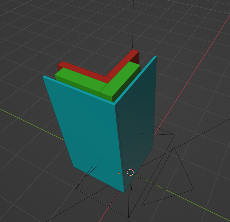
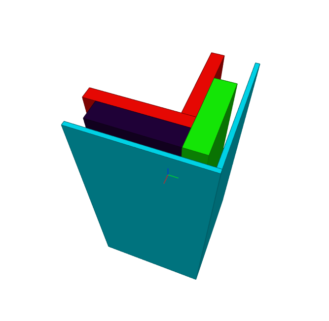
So if you ONLY set the IfcStyle colour it works perfectly:
I couldn't fix you materials so I just set some new ones (and the one insulation wall has the original material which I cant remove for some reason so it's still wrong but the principle is still there
So dont set the IfcMaterial colour, just do the IfcStyle colour
sounds cool... how do you do that?
When you create the Ifcmaterial leave it as the default (dont adjust the base colour),
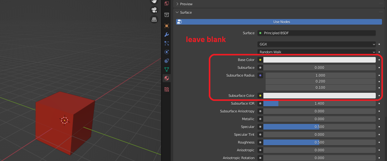
and then add the colour for the IfcStyle
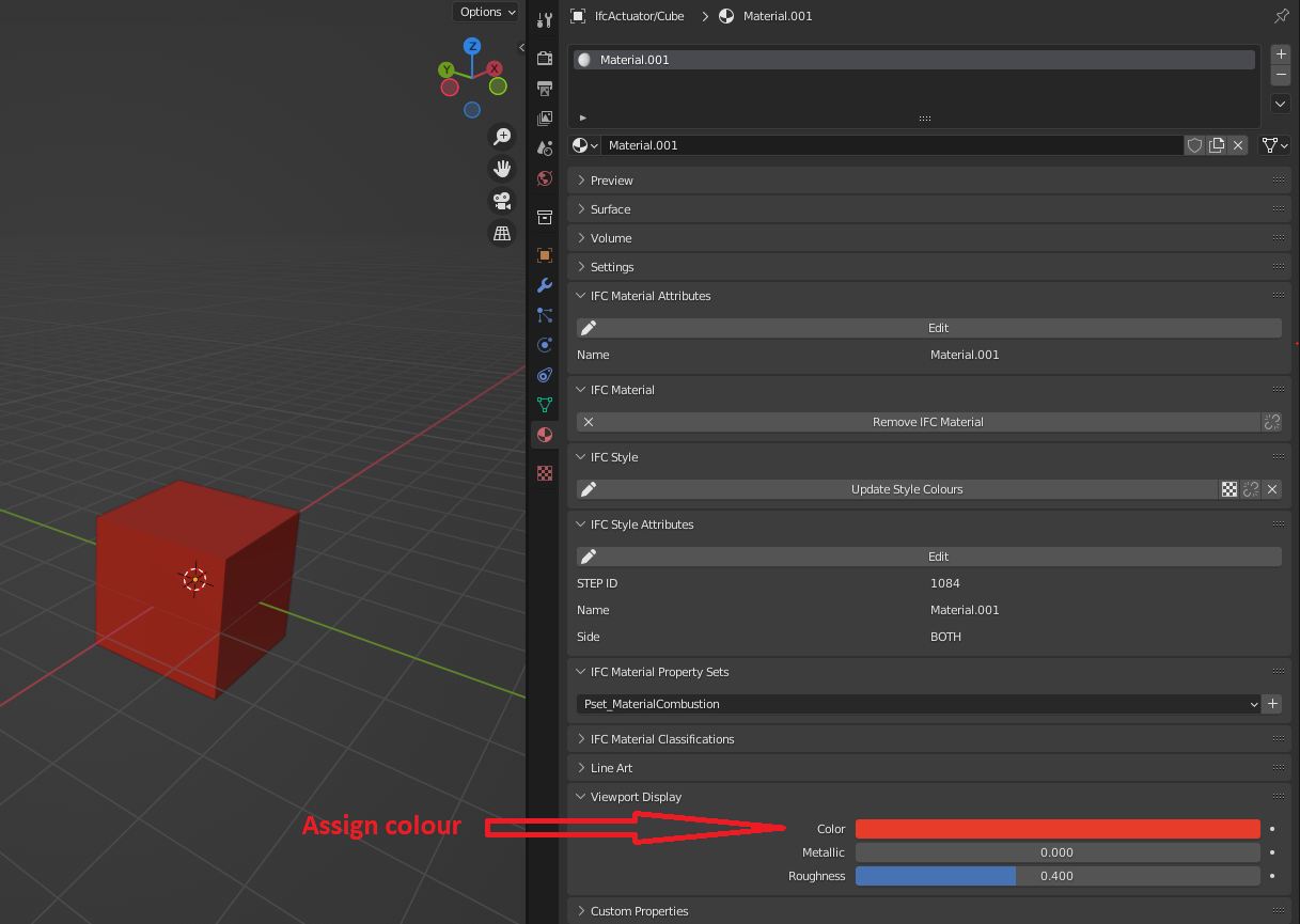
And it should work?
nice! good to know.
The UI is begging for this to be under the 'IFC Style' panel.
Ya, i think since the viewport display is already there @Moult didn't duplicate it, but it should definitely be under Ifc Style labeled 'IfcStyle colour'
same problem here sometimes ...
In Nemetschek Allplan one only can define one color for a object. In Ifc a object has two colors the representation color and the material color. Nemetschek Allplan and AFAIK Nemetschek Vectorworks as well do write sometimes different colors for representation and material ... In FreeCAD I implemented a warning if they differ. There is even a third color. If a viewer has problems to read a color at all in most cases the viewer uses grey, but most material used in my models is concrete and concrete is grey. Thus sometimes one might think everything is ok, but it is grey because nothing is ok. ...
Colors in ifc are terrible ...
all 100 computers in the company I work in do have these both installed for exactly the reason you mentioned :-) (except the Revit stuff. We do not use Autodesk software)
on my one is in addition BlenderBIM, FreeCAD, IfcQuery and Solibri installed
@Coen:
Have you ever tried one of the cheap AddOns of BIMVision?
and Solibri installed
While I think Solibri does all kind of things to make the "free" version unattractive
by adding all kind of hurdles ... I gave up a few years ago.
But maybe that has changed in recent years.
I added a PR, here...
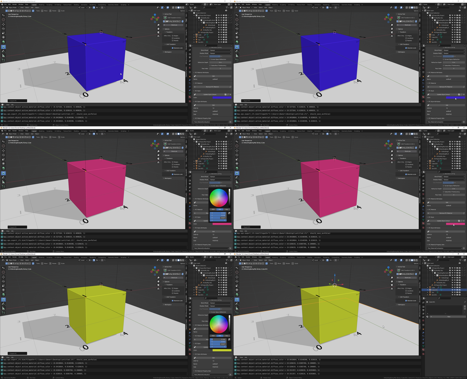
https://github.com/IfcOpenShell/IfcOpenShell/pull/2606
There are quite a few misunderstandings around colour in IFC which has led to an incredibly poor user experience, and the way colour is presented also has a lot of confusion. Let me try to clarify how things actually work and hopefully we can brainstorm a good UX solution to clearly describe it (@theoryshaw's PR and @Ace's proposal is only half a solution - but a good starting point).
First, let's define an "IFC Material" as a physical material (i.e. steel, wood, etc) that has no colour or appearance data. Only pure physical properties. In contrast, an "IFC Style" contains appearance data (e.g colours, stroke thickness, fonts, etc) ... and there are different subtypes of IFC Syles: IFC Surface Styles (e.g. the appearance of surfaces, such as polygons or BReps or Solid Surfaces), IFC Curve Styles (e.g. the appearance of 2D curves, lineweights, etc), IFC Text Styles (The appearance of textual annotation / fonts / etc), and I think one more but I don't have the docs open. Given these subtypes you can see why it is logical to separate IFC Materials from IFC Styles, compared to the CG world where material = style (which is not true for IFC). For convenience, let's say IFC Style = IFC Surface Style because that's what we're mostly interested in here.
IFC geometry may have, in order of priority (higher priority overrides lower priority):
(There is technically another way but nobody uses that other way and it's ridiculous and IFC should probably delete it.) Also note that this is quite similar to how CG can have colours assigned either to objects directly or to object materials, or to objects sharing mesh data or objects not sharing mesh data ... which is quite complex too but I don't hear the CG guys complaining.
So now the question is ... what do we mean by "Colour"? An IFC (Surface) Style can define different types of colour. It can define a "Shading" colour, this is a simple colour that you see in a viewport (like the Blender viewport). It's purely aesthetic and has no other intelligence. This is equivalent to Blender's "Viewport Colour".
Another "Colour" is a "Rendering" colour. This is not just a simple viewport colour, this now can have multiple colours, such as a "Diffuse" component, a "Specular" component, a "Emissive" component, etc all depending on the rules of the Illumination / Lighting rendering engine. In the case of IFC, it follows the rules of glTF/X3D, so the colours (plural!) you specify follow the different lighting models in glTF/X3D. Because Blender is capable of being glTF compatible, this translates to particular Blender material node tree setups (and changing the base colour in the default BDSF node in Blender is effectively changing this colour). However, other IFC viewers like Solibri, BIMVision etc do not have rendering capabilities like Blender. And therefore they almost certainly will not show these "Rendering" colours. Instead, they will only show the simple "Shading" colours described above. This leads to a ton of confusion by users. Which colour is correct? Both! (If both exist) The BlenderBIM Add-on is super unique because we support both because we support rendering!
Then there is another "Colour" called "Texture Colour". These are rendering colours that come from an image texture instead of just a single RGBA value. The image texture may either have a single "bbox stretch mapping" which is very suitable for single image planes for signage and such on buildings, or it may have UV coordinates for the texture mapping. The BlenderBIM Add-on has full support for stretch mapping but only "save" support for UV coordinates (not loading, unfortunately). Like "Render Colours", these follow the X3D 4.0/glTF standards and therefore you can have multiple textures for diffuse, specular, normal, etc components depending on your nominated reflectance method.
There is another type of "Colour" I'll call "Photometric Colour" (IFC has two subtypes for this: Lighting and Refraction). This is the type of colour defined for illuminance and luminance photometrically validated light simulation. As you know, the colours Pixar uses are beautiful, but completely wrong for light simulation (hint: anything pure white or pure black is instantly wrong). Because buildings are physical, IFC supports a "Photometric Colour" too, and this one can be fed into simulation software like Radiance. No IFC viewer will ever show you this colour (not even the BlenderBIM Add-on) because none of them support light simulation (the BlenderBIM Add-on used to show it a long time ago, but the feature was deleted and I need to readd it in a smart way to minimise confusion).
Then there is a final colour known as an "Externally defined style". This is a style that is completely 3rd-party to IFC. IFC recognises that as an ISO standard it will never keep up with the myriad of clever innovations by the CG industry and there will always be interesting shaders by third parties. This effectively lets you delegate the entire shader to an external URI - how that is interpreted is totally arbitrary. We actually used to support this in the UI and support arbitrary Cycles node trees - this is what you might use if you want to support complex Cycles, Renderman, etc shader setups.
In summary: IFC Material != IFC Style. IFC Material has no colour data. IFC Styles had many substyles, but IFC "Surface" Style is the one we're mostly talking about. Colours can be a "Shading Colour", or many "Rendering Colours", "Texture Colours", "Photometric Colours", or "External Colours". You can simultaneously have all 5 colour types defined and use them in different situations.
I hope this explanation has helped. The BlenderBIM Add-on has the most advanced colour and texture support that I know of (except for that other one which does support texture coordinates, but I don't think supports the other rendering parameters) so now the problem is UX: how is this best presented to users to minimise confusion. I like @theoryshaw's start, but it's a start - I'd like to see something that is comprehensive to the nature of IFC Styles.
Anyway I'm on holiday right now so I'll have to delay a closer investigation until I get back.
Ping @bernd @yorik - I also hope FreeCAD (especially with the new Native IFC initiative) can also have top notch IFC style support.
This was unexpected. I expected a simple answer and got a thesis back on the use of colours in IFC. Very much appreciated everyone! :-D
In my real (virtual CAD) world ....
although today,
the differences between vector drawing, CAD, BIM until 3DCC Apps are overlapping quite a bit.
CAD : Object Colors :
Line Colors, Fill Colors, Hatches, (even assigned images or transparencies)
Usually defined by Object Attributes/Properties or by Layer/Classes
They DO influence the Object's appearance
BIM : Materials :
Which i call "Physical Materials"
Which are basically just Data Information in first place
They DO NOT influence the Object's appearance per se
3DCC : Materials :
Which i call "Rendering Materials"
Which can use Colors, Image Textures, Procedurals, .... in all kind of Material channels
Their only purpose IS to influence the Object's visual appearance
If I got right what I read above,
IFC Standards will at least translate : 2. BIM : Materials,
just like any other IFC Tag information.
But I am a bit unsure now what happens in IFC with ,
1. CAD : Object Colors :
Line Colors, Fill Colors, Hatches, (even assigned images or transparencies)
exactly,
or what IFC (4.x ?) supports from : 3. 3DCC : Materials
at all.
While I expect even some discrepancies between IFC standard supported features
and what IFC exporting or IFC Viewing Apps will deliver at the end.
@zoomer IFC supports all 3 as described in my post (though I didn't go into detail on 2D CAD styles)
Thanks @Moult
I would not have expected that.
So it is more about checking my BIM CAD's exchange quality and/or
checking IFC in multiple Viewers Apps.
Usually in the past few years I mostly got only 1-2 basic transparent Materials,
if Glass Panes were transparent at all or just partly.
In more recent imports I got mostly all used Materials into CAD back, but not assigned to
any Layer or Object and no useful Materials Settings or even Texture Maps/Paths.
I think I should also check in BlenderBIM to estimate what my IFC exports really contain ....
Apologize for reopening this thread, i did not find an existing thread that might cover my question.
I am teaching my wife, and myself, to use BB a bit more as a couple exerise. We are modeling up our new apartment.
When making a new window resource that should fit in with what we have, i notice whenever i add a new window type, or when activating "Window Parameters", all material colour blanks out when compared to the pre-defined window. I am more than comfortable enough to go into the edit function of the window block and select all faces to reassign some material properties. What i would like to know is if there is a possibility to have for ifc objects predefind ifc materials when adding new typs or changing its parametric values. If every single time you want to make a new window, or change dimensions, and then reassigning new material is a bit of an irritational extra work.
When using the 'parametric window', i don't think it's currently possible to assign individual material to the frame and glazing, if that's what you're asking.
related: https://github.com/IfcOpenShell/IfcOpenShell/issues/2981
What I usually do is to set the modified window as a different type, then I go to edit mode from where I can assign different materials to selected areas of the modified window. Since the original type WT01 has Frame and Glass materials, I use them for convenience.
Thank you Steve for verifying the same methode as I used. It works, though I would assume some where down the line it should be automated with standard values. I see that some of our projects we recive from the architecture firms have well over 20-30 different window resources. I guess currently the only workaround is to premake a costume arc pack and load it in for each new project.
hi @Ole_Marius_Svendsen
I now understad your original post. Indeed a way to separately identify parts within a door or window would be nice to have without entering into their mesh.
However, for basic use applying a frame material to the whole window first, select the glass faces and apply the glass material takes just a few clicks, after that you can use that type in your workflow, but I am relatevily new to Blender and don't know Archipack (it's next on my todo list)
cheers