@steverugi said:
please let me know if you see some other query that could be of use
So after playing around a bit I came unto a couple of schedule/spreadsheet related questions:
How do you place an spreadsheet onto a sheet? I now used export spreadsheet to ods>import schedule>generate>link to sheet. This however gives a schedule that takes some steps to update, and for which the layout is too basic. I deleted a column, but it still remains and I changed the width but that didn't import in the schedule (both done in LibreOffice Calc). Is it possible to directly link a spreadsheet or is there another way?
Can we put in formulas in the spreadsheet like Excel?
How to query other values, like the global z of an object or the orthogonal height of a project (in georeferencing)?
And if we combine the 2 questions above, how would you get a value that substracts the global z of an element of the orthogonal height of the project? This example is useful for NAP in the Netherlands or AHD (au), NAVD88 (usa), ODN (uk). Being able to use formulas would be very cool!
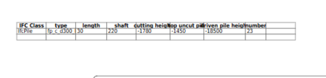
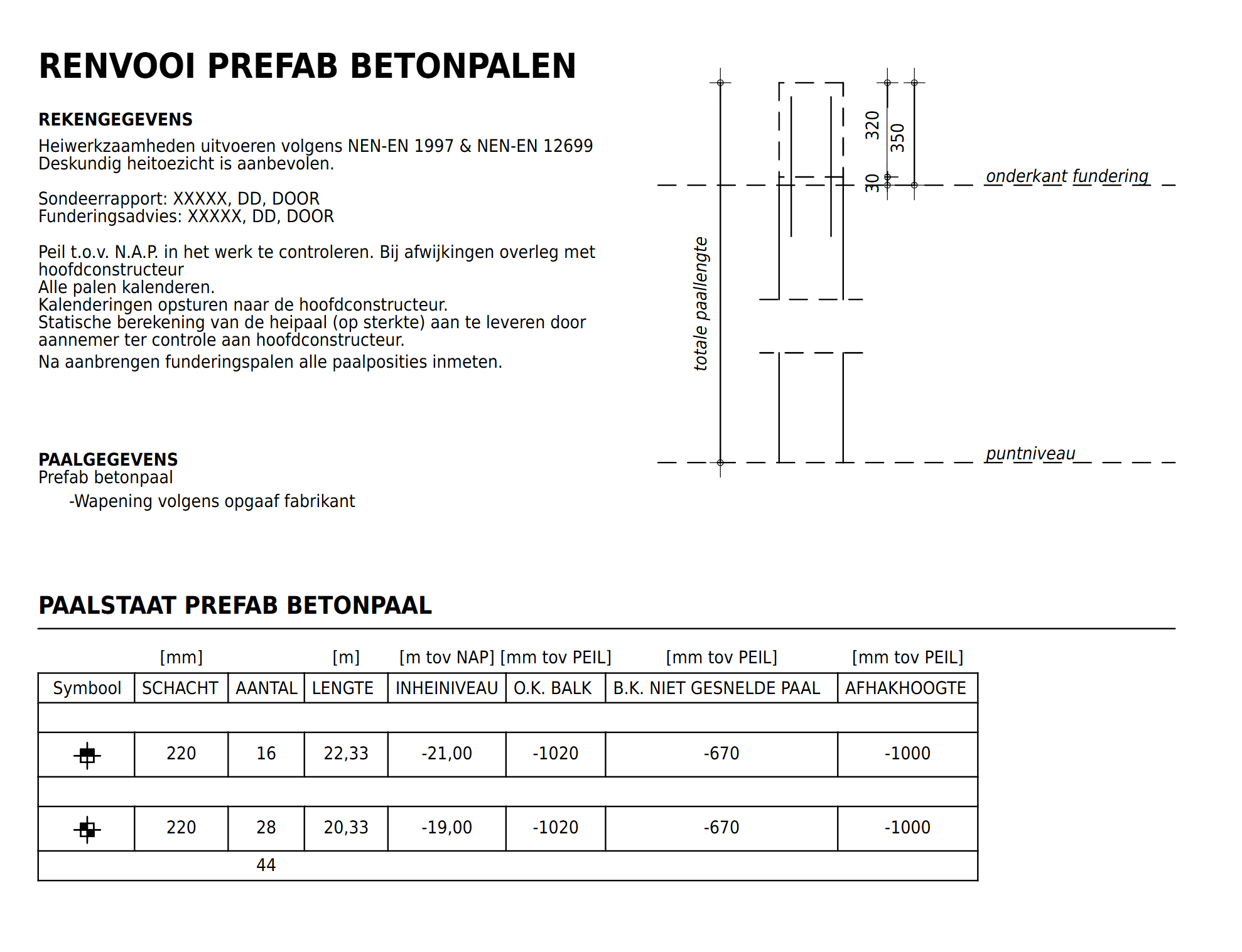
Is it possible to let Bonsai calculate our own properties? Let's say I want to see radius or the diameter of a pile (shaft in the spreadsheet) calculated and I make a property with IfcParameterValue for it, is it possible? So I guess it would be a property with a formula behind or in it.
2 other questions:
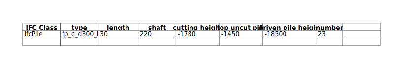
When I calculate quantities for my pile layout plan, the piles get a length of 30 (mm). I recalculated 2 times but don't know what the issue could be. They are 5000 mm and @steverugi also got that in his schedule here:
So after playing around a bit I came unto a couple of schedule/spreadsheet related questions:
1. How do you place an spreadsheet onto a sheet? I now used export spreadsheet to ods>import schedule>generate>link to sheet. This however gives a schedule that takes some steps to update, and for which the layout is too basic. I deleted a column, but it still remains and I changed the width but that didn't import in the schedule (both done in LibreOffice Calc). Is it possible to directly link a spreadsheet or is there another way?
I need to get back to you on this, admittedly I hardly use drawing output in Bonsai, I think you can start from Drawings and Documents > Schedules but I haven't tried it yet
Can we put in formulas in the spreadsheet like Excel?
no
How to query other values, like the global z of an object or the orthogonal height of a project (in georeferencing)?
you can try to use just z in your query column
And if we combine the 2 questions above, how would you get a value that substracts the global z of an element of the orthogonal height of the project? This example is useful for NAP in the Netherlands or AHD (au), NAVD88 (usa), ODN (uk). Being able to use formulas would be very cool!
It would indeed but as of today's version I don't think simple operations are allowed in the Spreadsheet, happy to be wrong here
Is it possible to let Bonsai calculate our own properties? Let's say I want to see radius or the diameter of a pile (shaft in the spreadsheet) calculated and I make a property with IfcParameterValue for it, is it possible? So I guess it would be a property with a formula behind or in it.
probably only by Python script, see my answer above
2 other questions:
5. When I calculate quantities for my pile layout plan, the piles get a length of 30 (mm). I recalculated 2 times but don't know what the issue could be. They are 5000 mm and @steverugi also got that in his schedule here:
you need to try different approach some entities are better captured with IfcOpenShell or Blender quantity take-off engine
is it possible to create a 3D object with only the symbol or model/Annotation/PLAN_VIEW represenation visible in plan? like a fire extinguisher?
no idea, sorry, hopefully others on this platform can chip in (same for the other questions)
cheers
@steverugi said:
I need to get back to you on this, admittedly I hardly use drawing output in Bonsai, I think you can start from Drawings and Documents > Schedules but I haven't tried it yet
Yeah I used this function, for which I imported the spreadsheet I exported from Bonsai to ods (with a bit of LibreCalc cleanup in between).
you need to try different approach some entities are better captured with IfcOpenShell or Blender quantity take-off engine
Ah I see, thanks!
And yeah, maybe I'm too early for these questions but I thought it might be possible ;) But thanks for answering!
For those interested: I created the symbols by precreating the symbol and classifying it as a IfcBuildingElementProxy.
Then I gave a new model/Annotation/PLAN_VIEW representation to the piles by choosing 'From Object' and then selecting the symbol. This way I can assign the same symbols to other objects and create a small symbol library.
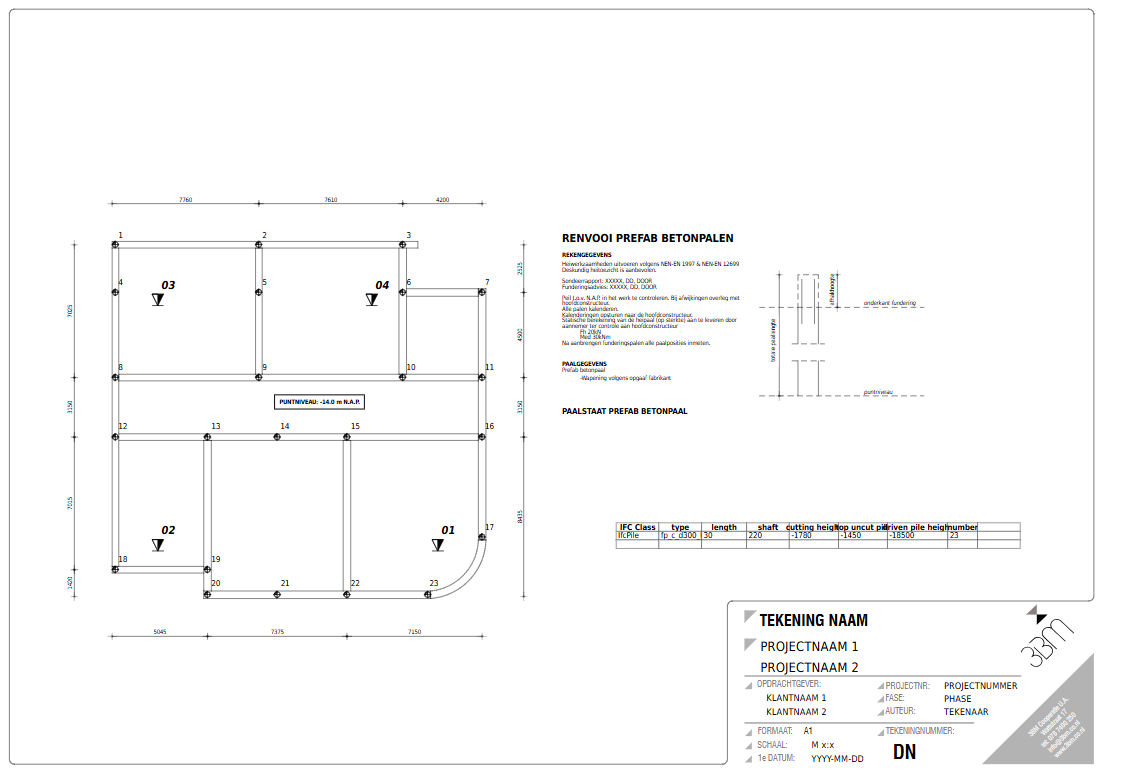
As the shedule /spreadsheet directly from Bonsai looked 'not-so-good' and doesn't support formulas [yet] , I got the values I needed and just made my own schedule that looked visually better as a drawing with annotations. Downside is that annotations in viewport are different to final annotations(size etc) so its not ideal. Also the values ofcourse dont update as it is just an annotation.
Look at the space I need to add manually (trial-and-error) with the text in the viewport as opposed to the space it creates in the drawing.
Downsides to this drawing are:
Manually tagging and numbering takes a lot of time, editing text in general isn't very efficient. I'm missing ability to tab (spaces don't register), give different markdown to different parts of the same text annotation, having to click edit and click save (is using 'Tab' possible?).
Values are manually added and not calculated. Will request formula capabilities for the spreadsheet soon on GitHub.
Dimension text is stuck above each other if too close. Makes dimension unreadable.
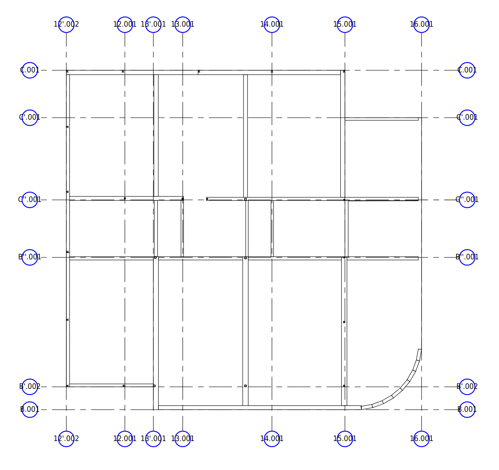
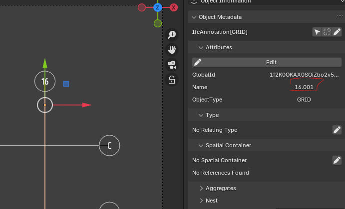
Grids are made by the workaround @theoryshaw mentioned. However when I want another drawing on another level they dont show up, so I remade them (duplicating drawings and annotaions to another level doesn't work for me, how do you do it?). These grids get their number by filling in 'Name' attribute but then Blender adds the .00X. How do I get those to not show on drawings?
Is it possible to choose between showing none of the end markers, only 1 side (and which) or both of the circles / end markers?
Is it possible to add a button to be able to choose representations for a drawing? e.g. I have two plan annotation representation, can I cancel out the 3D representation and one of the 2D annotations only for the drawing? Or if I don't want the 2D annotation, to export the model only?
Something like an include/exclude button like this or there might be a better way.
If anyone knows a better or more IFC technically correct way to do symbols or anything else I did for this model I would like to know!
These grids get their number by filling in 'Name' attribute but then Blender adds the .00X. How do I get those to not show on drawings?
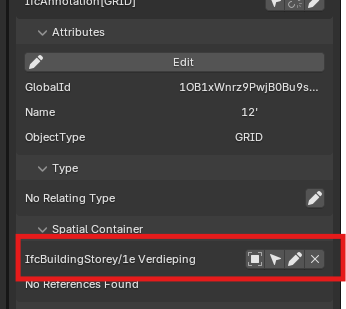
Okay so I found out that they get their .00X if they are in the same spatial container as the grids of other levels. Duplicating the grids removed them from all spatial containers, so changing this to the new level allowed me to remove the .00X parts in the names. Is it possible to say duplicate annotations to this level and with this spatial container? this would remove the issue I think.
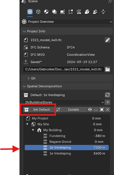
I also found out all my new objects were placed in the wrong spatial container (placing them from a plan view of another storey). You need to choose your storey here and set it as default before placing objects. Then they're in the right spatial container. Is there a way to link the spatial container to the floor plan you're adding the elements in? So that when I switch to the roof plan the objects are automatically placed at roof level?


Comments
So after playing around a bit I came unto a couple of schedule/spreadsheet related questions:
How do you place an spreadsheet onto a sheet? I now used export spreadsheet to ods>import schedule>generate>link to sheet. This however gives a schedule that takes some steps to update, and for which the layout is too basic. I deleted a column, but it still remains and I changed the width but that didn't import in the schedule (both done in LibreOffice Calc). Is it possible to directly link a spreadsheet or is there another way?
Can we put in formulas in the spreadsheet like Excel?
2 other questions:
Much thanks!
Hi @jes_r
I need to get back to you on this, admittedly I hardly use drawing output in Bonsai, I think you can start from Drawings and Documents > Schedules but I haven't tried it yet
no
you can try to use just
zin your query columnIt would indeed but as of today's version I don't think simple operations are allowed in the Spreadsheet, happy to be wrong here
probably only by Python script, see my answer above
you need to try different approach some entities are better captured with IfcOpenShell or Blender quantity take-off engine
no idea, sorry, hopefully others on this platform can chip in (same for the other questions)
cheers
Yeah I used this function, for which I imported the spreadsheet I exported from Bonsai to ods (with a bit of LibreCalc cleanup in between).
Ah I see, thanks!
And yeah, maybe I'm too early for these questions but I thought it might be possible ;) But thanks for answering!
would be a sweet feature request.
True! Maybe a dumb question, but how do we put in feature requests? Via an Issue on github or something else?
Not dumb at all!... a most wonderful question.
Yes, feature requests can be logged on https://github.com/IfcOpenShell/IfcOpenShell/issues
Update on the drawing and model (WIP):
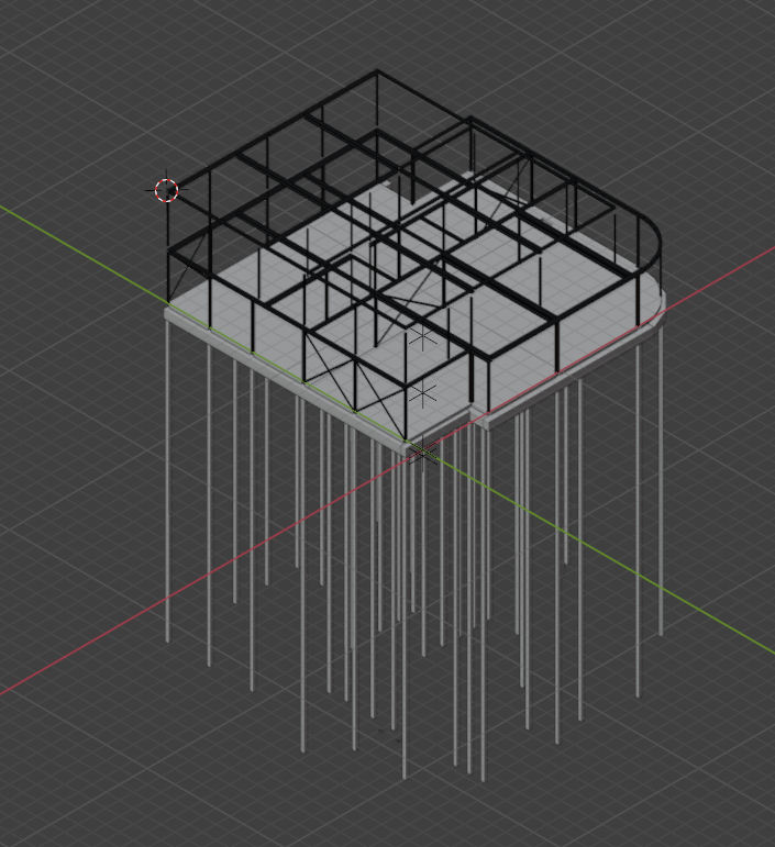
For those interested: I created the symbols by precreating the symbol and classifying it as a IfcBuildingElementProxy.
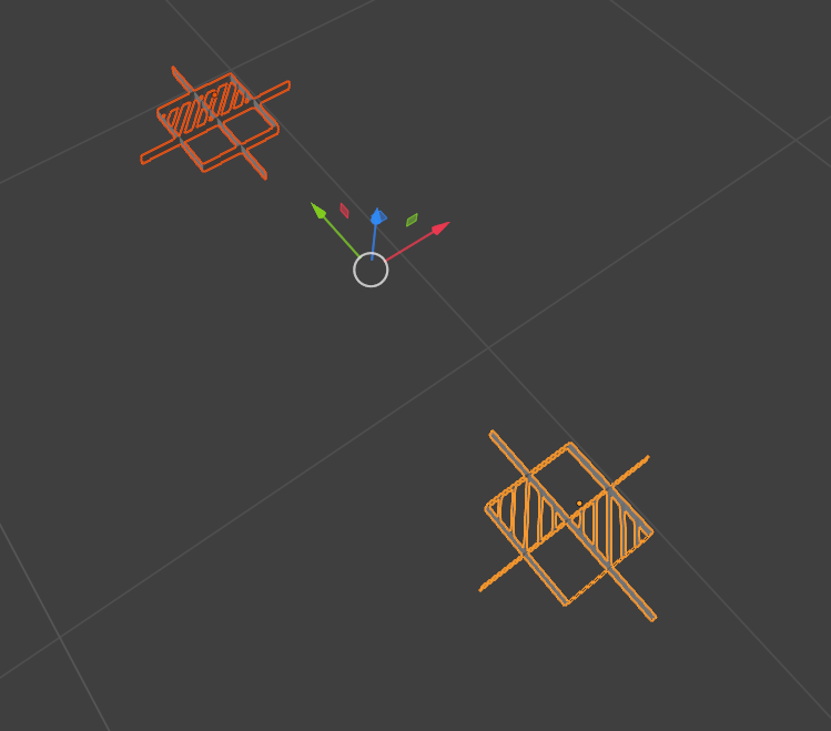
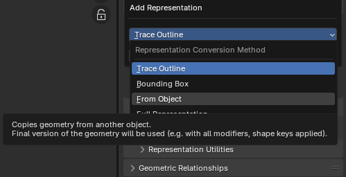
Then I gave a new model/Annotation/PLAN_VIEW representation to the piles by choosing 'From Object' and then selecting the symbol. This way I can assign the same symbols to other objects and create a small symbol library.
As the shedule /spreadsheet directly from Bonsai looked 'not-so-good' and doesn't support formulas [yet] , I got the values I needed and just made my own schedule that looked visually better as a drawing with annotations. Downside is that annotations in viewport are different to final annotations(size etc) so its not ideal. Also the values ofcourse dont update as it is just an annotation.
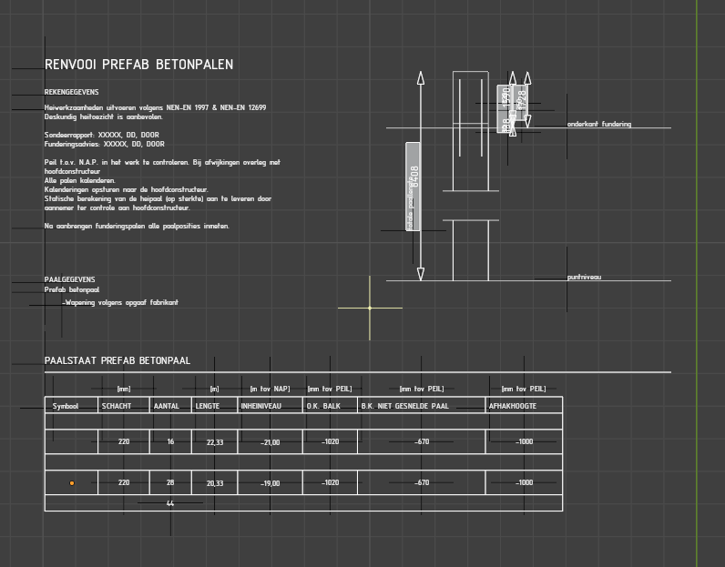
Look at the space I need to add manually (trial-and-error) with the text in the viewport as opposed to the space it creates in the drawing.
Downsides to this drawing are:
Grids are made by the workaround @theoryshaw mentioned. However when I want another drawing on another level they dont show up, so I remade them (duplicating drawings and annotaions to another level doesn't work for me, how do you do it?). These grids get their number by filling in 'Name' attribute but then Blender adds the .00X. How do I get those to not show on drawings?
Is it possible to choose between showing none of the end markers, only 1 side (and which) or both of the circles / end markers?
Is it possible to add a button to be able to choose representations for a drawing? e.g. I have two plan annotation representation, can I cancel out the 3D representation and one of the 2D annotations only for the drawing? Or if I don't want the 2D annotation, to export the model only?
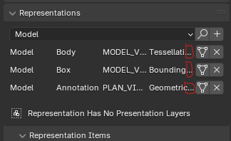
Something like an include/exclude button like this or there might be a better way.
If anyone knows a better or more IFC technically correct way to do symbols or anything else I did for this model I would like to know!
Okay so I found out that they get their .00X if they are in the same spatial container as the grids of other levels. Duplicating the grids removed them from all spatial containers, so changing this to the new level allowed me to remove the .00X parts in the names. Is it possible to say duplicate annotations to this level and with this spatial container? this would remove the issue I think.
I also found out all my new objects were placed in the wrong spatial container (placing them from a plan view of another storey). You need to choose your storey here and set it as default before placing objects. Then they're in the right spatial container. Is there a way to link the spatial container to the floor plan you're adding the elements in? So that when I switch to the roof plan the objects are automatically placed at roof level?