

IFC "expansion"

I recently discovered an interesting phenomenon when using Revit. A 10M RVT file actually exported a 140MB IFC file. The IFC exported by other 10MB RVT files is 2-5 MB.
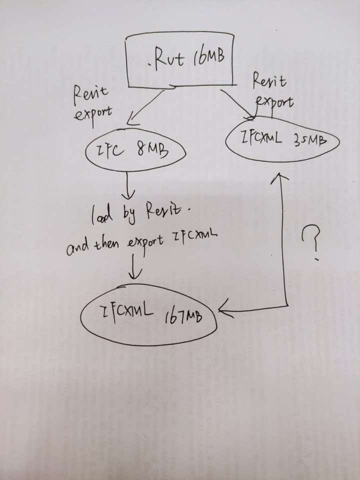
In addition, there is a 16MB RVT file, 8MB IFC, and 35MB IFCXML are exported through RVT. Then this 8MB IFC file was read by Revit, then the exported IFCXML file reached 167MB, which is about 5 times the original IFCXML file. as the picture shows
This kind of "expansion" seems strange, I want to explore the reasons for it.
Tagged:
Comments
Revit is notorious for inefficient mesh descriptions in IFC. The primary cause of this is due to inefficient swept / blend curve handling. Internally, Revit stores the curve, but converts it to a mesh when exporting. This can result in two Revit files that look extremely similar, but one may have a huge size in IFC whereas the other will not. See this article which explains this: https://wiki.osarch.org/index.php?title=Revit_and_IFC_Geometry
When Revit re-imports the IFCXML, it is forced to meshify everything, since Revit's parametric geometry round-tripping isn't very good (but then again, most software's geometry round-tripping is pretty poor). This results in a further explosion of filesize.
If any CG modeler ever modeled meshes the same way that Revit does it under the hood, they would get fired. Simple things like egress exit signs which should be 6 polygons in any sane software ends up being over 500 polygons in Revit due to how Revit decides to show it in IFC - if the user has inadvertently triggered one of the problems listed in that wiki article. For this reason, IFCs produced from the BlenderBIM Add-on actually can contain much more complex buildings at a fraction of the size of the IFCs coming out of Revit.
If the AEC industry understood mesh topology more, these problems can be avoided, and we wouldn't be having all of these scalability issues in larger projects.
What about other geometric modeling paradigms other than mesh? And BRep?
I think is exactly the area #osARCH development can address that will get us the most mileage in the industry.
How many geometric objects we have?
Some months ago I suggested to Dion build a spreadsheet and see which geometric paradigms are suitable for which geometric/building objects?
But Dion goes his own way, which is based on priorities his firm, IfcOpenShell, and FreeCAD have, not what's better for all
@ReD_CoDE your disparaging attitude is often irksome and counter productive.
A couple of months ago I was reading some posts on FreeCAD community from some years ago, when some were requesting implement "OpenSceneGraph" when FreeCAD was chosen a bad solution, and I'm not sure even today FreeCAD has implemented it
This is just a small example, how people, especially in open source projects choose the wrong path and for years follow their wrong path
A few studies:
A file containing 1,000 walls exported as arbitrary profile extrusions, versus the same 1,000 walls exported as IFC4 tessellated meshes both result in 1,736kb. But let's break it down for you to draw your own conclusions:
For those curious, this is a tesselated mesh box (9 SLOC, 497 bytes - can be made as funky as you want) - note how buildingSMART retains the indexed polygonal face as a separate entity, if merged into the face set, it could be made a lot more efficient:
Theoretically if buildingSMART decided they wanted to give some love to meshes, it could turn into this (3 SLOC, 292 bytes):
Arbitrary closed profile def (13 SLOC, 484 bytes, ~36 bytes per added vertex - limited to a simple extrusion):
Rectangle profile def (8 SLOC, 311 bytes - limited to rectangles only):
Note that for disciplines that use pipes or rebar, or really any circular extrusion, this test does not apply, and a parametric extrusion is definitely the way to go.
For bespoke shapes - it's kind of a half-and-half, it's hard to say, and really depends on the shape. It should be considered case by case, and use the best tool for the job.
Weird Revit! This expansion is really weird.
@Moult I relayed your point of view in Chinese and sent it to the Chinese forum. So many users especially recognized your point of view. Besides me, there are at least three Chinese designers who have found similar problems. Thank you again!
@shanmama , which Chinese forum ?
I translated this question and related answers into Chinese and posted them to my CSDN blog
It is also true that in many cases a mesh (even more if it allows complex faces with more than 3 vertices, or even holes) is not worse than any other geometry type.. It is as easily parseable and editable. Even revit sometimes handles well such objects :)