

[Blender & IFC] Beam Systems

Split from: https://community.osarch.org/discussion/comment/8700/#Comment_8700
@Coen said:
Slightly related, are there any tools in Blender which can create a Beam plan/system just like in Revit? With span direction and boundary?
The following is the only way i know.
video: https://www.dropbox.com/s/nry2o5pqq0n5zb4/2021-09-10_11-15-10.mp4?dl=0
Unfortunately, however, IFC doesn't support arrays, as far as I know, so this would not translate into the IFC file.

Comments
Well, you could make an array modifier modifier in Blender, then split by objects. But for scalability it's not a good solution.
This Boolean solution is an interesting solution, but I am thinking about ways to change the span direction too.
I have attempted to make a very basic beam system script. The idea was I used curves to extrude along so the beam profiles are interchangeable.
I deliberately tried to avoid using the Array Modifier because I wanted be able to translate it directly to IFC .
Next step is thinking on how to let the user create a boundary line .
I want to use this boundary line to create a an Void Box to be able to cut the beams with a Boolean tool like in the example @theoryshaw provided.
Here is the result
Here a .gif demo of what I am trying to achieve.
https://github.com/C-Claus/02_Blender_Python_scripts/blob/master/beam_system.py
NOTE: I see I made a mistake, the center to center distance, is not center to center, but geometry point to geometry point and I set the geometry point on the corner of the beam.
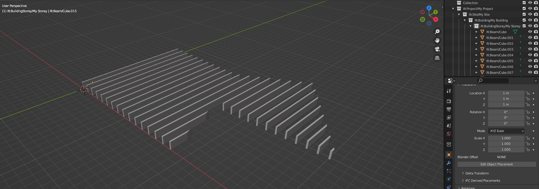
Disregard everything I posted above, different approach, I converted curves to meshed and extrude them..
The mesh result is easier to export to IFC
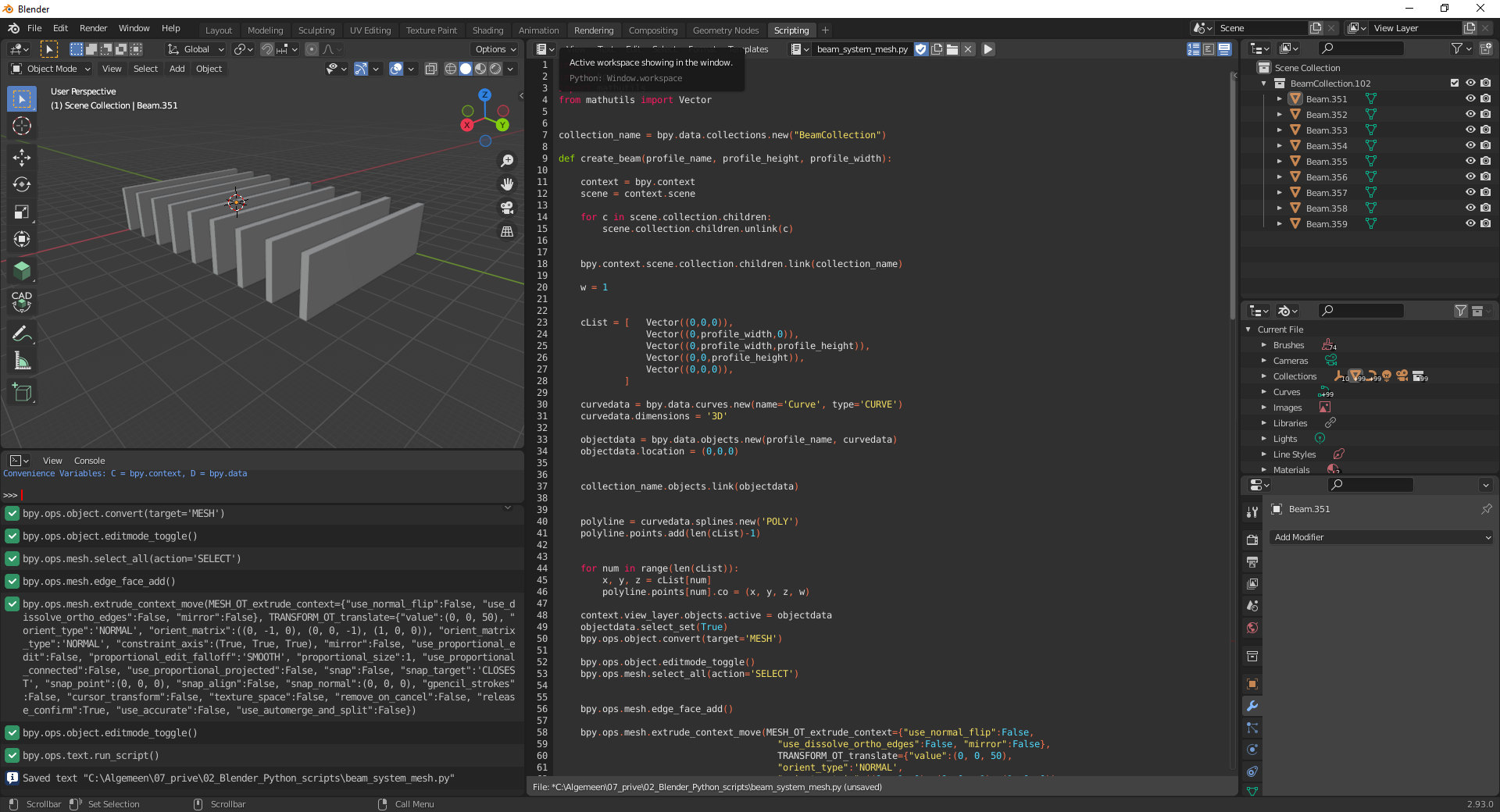
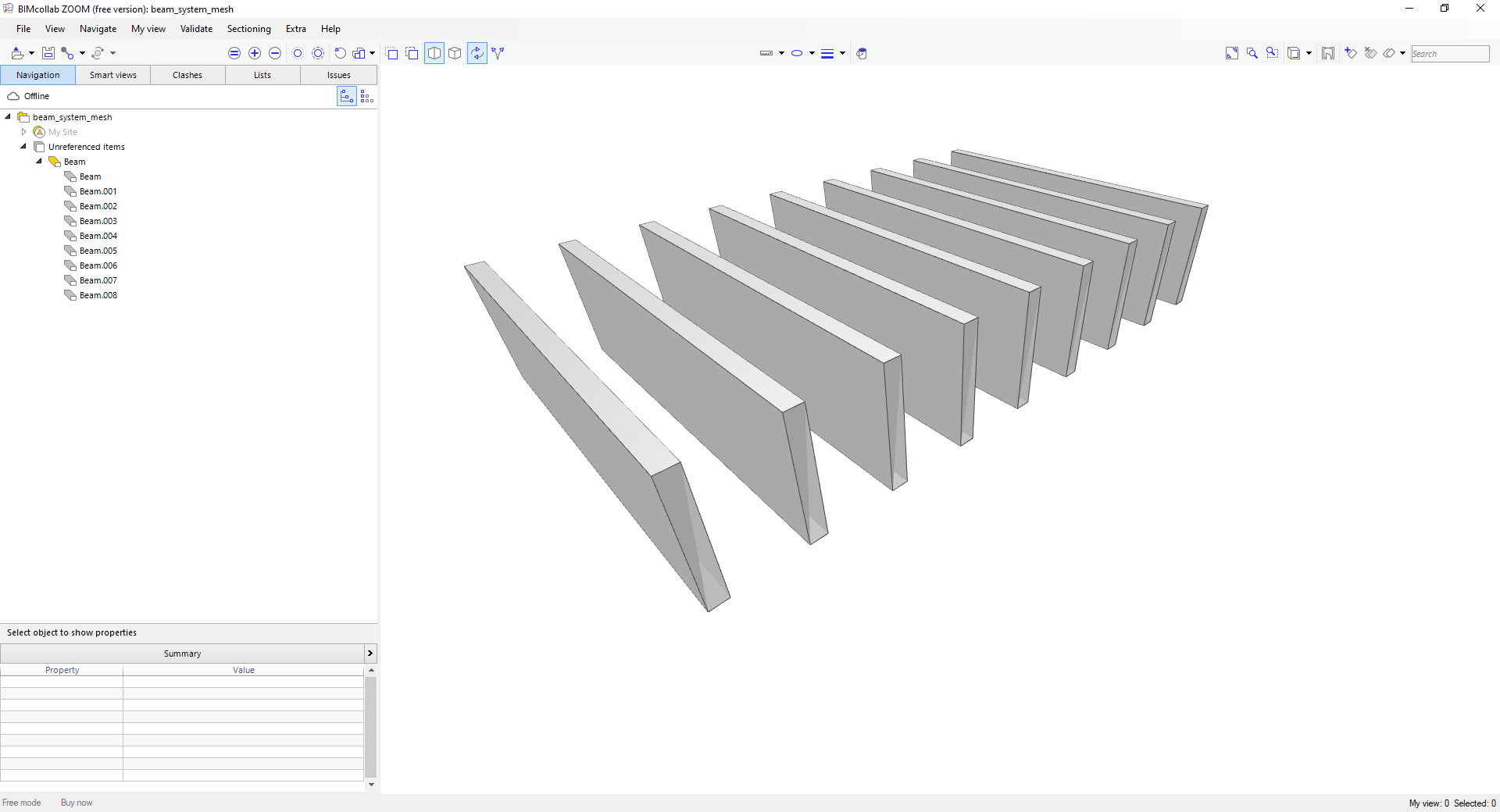
The result
https://github.com/C-Claus/02_Blender_Python_scripts/blob/master/beam_system_mesh.py
Ah, so much to do. In short, a beam system is no different to any other parametrically generate object(s) like stairs, railings, facade systems, and so on. What happens is that right now, any specially generated object will be marked with a pset saying that it is generated from a particular engine. That engine will then know how to deconstruct the IFC definition(s) to and from whatever you use to generate it, whether it's arrays, or a script you've written yourself.
However, this system has not been formalised, though I have got it working in simple cases (like generating extruded areas either horizontally or vertically layered elements).
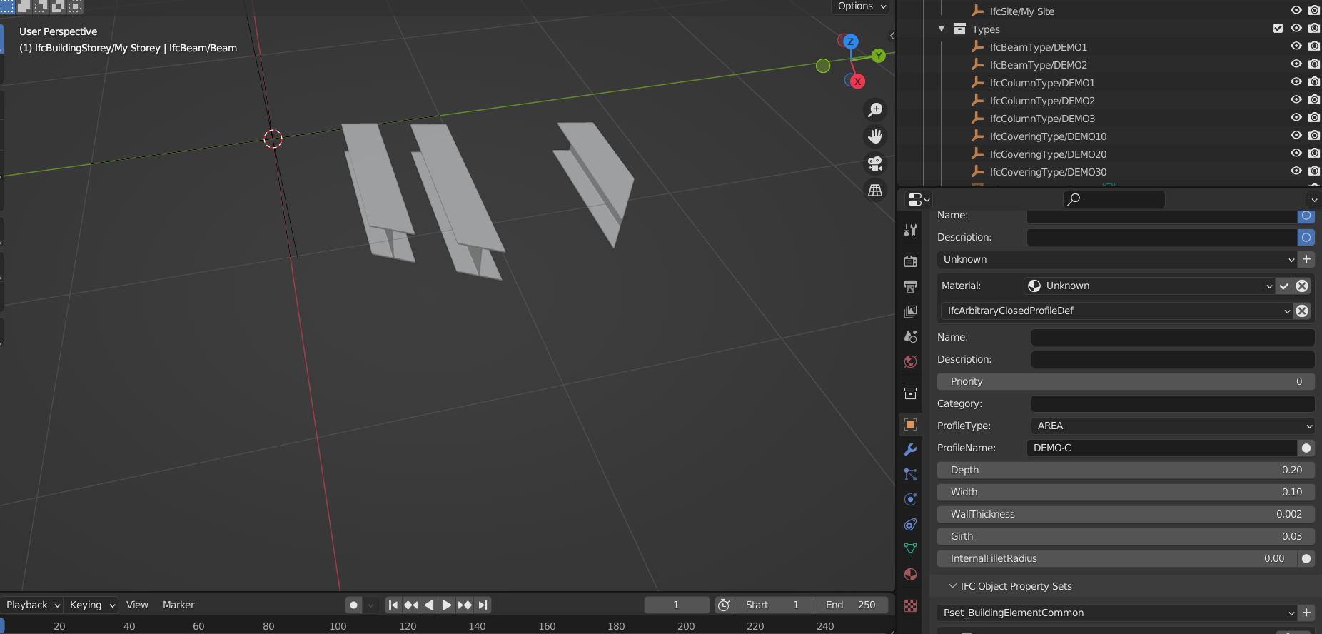
Also note that beams are best presented using an IfcMaterialProfileSet. This will allow the cardinal point to be parametric as well as the profile to be easily exchanged. Examples of this are given in the demo library file. A full profile manager is being built as well.
@Moult
Just curiously and politely inquiring about the progress :-)
Another point, I have gained some experience now with the Blender API.
And I was thinking about the following you wrote:
Well, this is my idea for a beam system:
I think the challenge here is how to roundtrip this in IFC, maybe someone has any idea?
I learned a lot since I posted in this thread, it's unfortunately not as easy as I would thought it would be in the beginning.
I am reading in the Building Smart documentation of IfcBeam
Is it possible to use the BaseQuantiies of an IfcBeam and make the modify array functionaly active in Blender?
How would Blender regonise that an Beam System is being imported?
How would it now which geometry belongs to the array?
Or should the array modifier completely be avoided and something should be built from scratch?
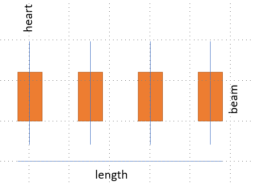
My attempt of drawing a cross section to filter out which parameters are needed for a beam system array.
@yorik How do you capture array's in IFC?
related:
@theoryshaw
Do you think IfcSlabElementedCase can be abused for a Beam System Array?
https://standards.buildingsmart.org/IFC/RELEASE/IFC4/FINAL/HTML/schema/ifcsharedbldgelements/lexical/ifcslabelementedcase.htm
Because I read in the definition
Seems to be used for roofs, but a beam system pretty much is a flat roof with beams.
@yorik @Moult @aothms Thoughts?
Generally, on arrays too. :)
Let's crack this nut!
Cool progress. -ElementedCase entities are deprecated, so I wouldn't base your solution on that. It ultimately also doesn't matter much because no intelligence comes from the entity type labels in the schema.
I agree with @Moult that this is fundamentally the same as other parametric systems. And there isn't much for that in IFC natively.
One comment I'd make is that opening elements can be applied to a higher level aggregation. You see that often in Walls with layers as separate IfcBuildingElementParts. The opening applied to the wall will get subtracted from the individual parts modelled as separate elements. But as I commented earlier based on @theoryshaw's approach, this is really not the correct use of openings. And clipping is unfortunately fully encapsulated into the representation items so cannot be generally shared.
You could potentially get funky with things like:
or some variations of this. That way at least geometrically the things relate a bit. But it'd be a challenge to find supporting software for this.
@aothms is it possible to place a beam using an offset relative to the placement of another beam? And then chain a series of beams together, but sharing the offset vector. This way a user would only need to edit a single entity to change the spacing of the whole series, or just change the placement of the first beam to move it all. An intelligent IFC editor would be able to notice this kind of data structure and offer to increase/decrease the number of elements in the series.
Well, interestingly, in IFC4.3 the location on IfcPlacement has been broadened to IfcPoint and not just cartesian point
That would allow some interesting use such as IfcPointByDistanceExpression IfcPointOnCurve IfcPointOnSurface
So intelligent placement of a single beam is within reach I'd say. The chaining I'm not so sure of.
The difficulty though is by expressing the parametrics in the placement, I feel like it'd be harder to control for geometry, if you'd need to fill an arbitrary bounded surface. That's why I started my reasoning from curve bounded plane.
I must say though that I find @Moult's approach "Explicit static IFC, intelligence in psets" more pragmatic than "Intelligent IFC, no support in software". The value of IFC is interoperability and in the case of IFC that's more dependent on implementations than on schema.
This is the kind of simple array functionality I was envisaging, basically each element is placed relative to the previous element:
The first
#163=IFCAXIS2PLACEMENT3Dlocates the start of the array, and the second#175=IFCAXIS2PLACEMENT3Ddefines the relative positions of each array element. So if you edit the offset in#172or the rotation in#174, all the elements in the array change to suit:@brunopostle
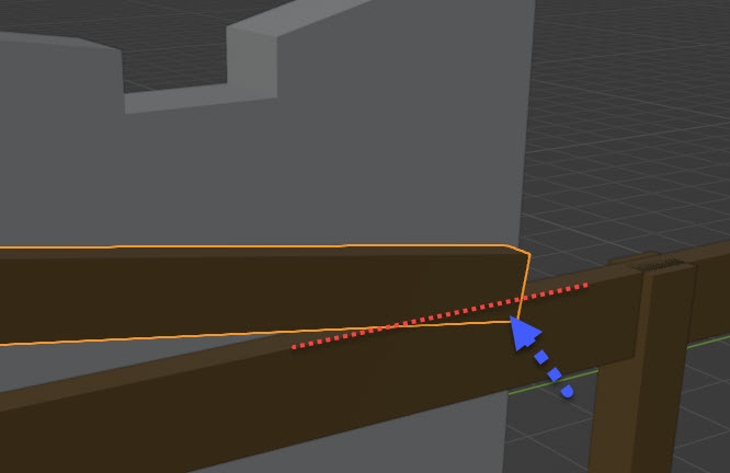
How would you define the 'boundary perimeter' of such an array?
I made a drawing to make myself more clear, the orange lines is the beam array. But how would one describe in IFC where the boundary of the array is?
@coen it would be 'simple' array functionality using existing IFC semantics, equivalent to Autocad 'rectangular' or 'polar'. You would be able to move the origin point, change the spacing and angle, but changing the number of elements or fitting a total distance/angle would require a bit of intelligence in the editing tool (potentially breaking in unpredictable ways).
Clipping is hard, you can generate all the beam representations and calculate a boolean result, or aggregate the elements and clip away with openings (as discussed above), each are nasty in their own way, but there is a basic problem: you want the IFC file to represent the true quantities. If you create a bunch of over-length beams and clip them, you have no longer have any idea what lengths are involved - you can request the total volume after clipping and divide by the cross-sectional area, but this tells you the total length, not the individual pieces.
Ideally you would create an array of centrelines, crop these with the perimeter, and use these centrelines as extrusion axes for your beams - IFC definitely doesn't support this.
This is a model where the beams are generated and then cropped to a perimeter, but there is no easy way to retrieve the sizes and number of beams from this model (note that the beam-ends are cropped at an angle by the boolean operation):
I abandoned this technique and now create the array of centrelines, crop to the perimeter (using Topologic), and then use these centrelines to define individual extrusions. Extracting a bill-of-quantities from this model would be straightforward (note that the beam-ends have square cuts):
A problem with this is that the IFC is largely uneditable, I can easily change the extrusion sections or material properties (and adjust vertical offsets if the overall construction depth needs to change), but if I want to change the spacing or perimeter then I have to regenerate from scratch. Now blenderbim/freecad could gain this kind of functionality, it could use the same technique to create arrays of elements that would easily be read and counted by other IFC tools, but it would need to stash all the information needed to remove and regenerate the cropped array in some special epset extension that no other tool would recognise.
@brunopostle
Is this worth building?
I think it's worth it. If the structure's in the IFC file, BB can use it 'natively'. Other programs like 'FreeCAD' could use it as well, if so desired. Build it and they will come. :)
ping @Jesusbill .. because i know he's felt this pain. ;)
Yes probably if this is what users expect. IFC is fundamentally a file format where every repeating item is listed individually, so any parametric information used to define/recreate/edit the array must be stored as additional data.
When I see the screenshots of your homemaker add-on beam array I am really impressed, I get the impression you already researched this topic extensively. Where can I find the code where you make an IfcBeam system array in your add-on?
@Coen it's all here: https://github.com/brunopostle/homemaker-addon/blob/main/molior/grillage.py
…though like everything else it isn't quite finished. You can play with it in the Homemaker-addon by creating a blender material named 'framing' and assigning it to faces that define a pitched roof.
This 'framing' style adds beams, rafters and battens to roofs, though the same system would do patent glazing, studword etc… I just haven't created those styles yet.
I found a way of modelling a 'dumb' beam system array with boundary, don't know if this worth a tutorial? Shall I write it out here for feedback to check if it's worth posting on https://blenderbim.org/docs/?
What would be a good way of swapping the beams for another type? Modelling or programming wise.
I also can't find a way to get IfcBeamType instances of unequal length.:
The following video shows how to create create an IfcColumnType: https://gitlab.com/openingdesign/The_Stead/-/blob/main/Tutorial Videos/10600~Creating Parametric Column Types.mp4
Creating a IfcBeamType is the same approach.
Maybe you know this already.
Thank you, I did not know, I see you used Ifc MaterialProfileSet in your clips, thanks will try to recreate it for IfcBeams.
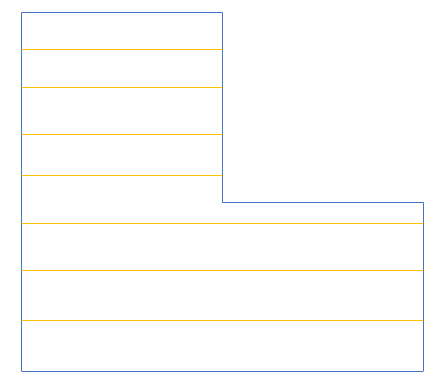
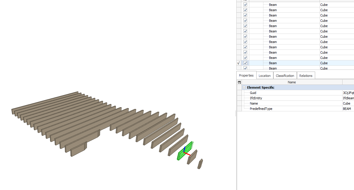
I made some beam instances, then cut them with a boolean to get the boundary,
Then I wanted to changes the profile dimensions:
They all changed back to their original length:
I could use the boolean geometry again to cut them again, but maybe there is a smarter way,
Unfortuately you have to click 'update representation', in the mesh properies, after you change the length, for the lengths to stay put.
Is this still the official way to cut the extremities of an IfcBeam/IfcMember? Could we cut an IfcElement by another IfcElement, or else simulate it by mapping the representation of an IfcOpeningElement on the one of the element to subtract? I have to cut this IfcMember by this other IfcMember :
Another beam question,
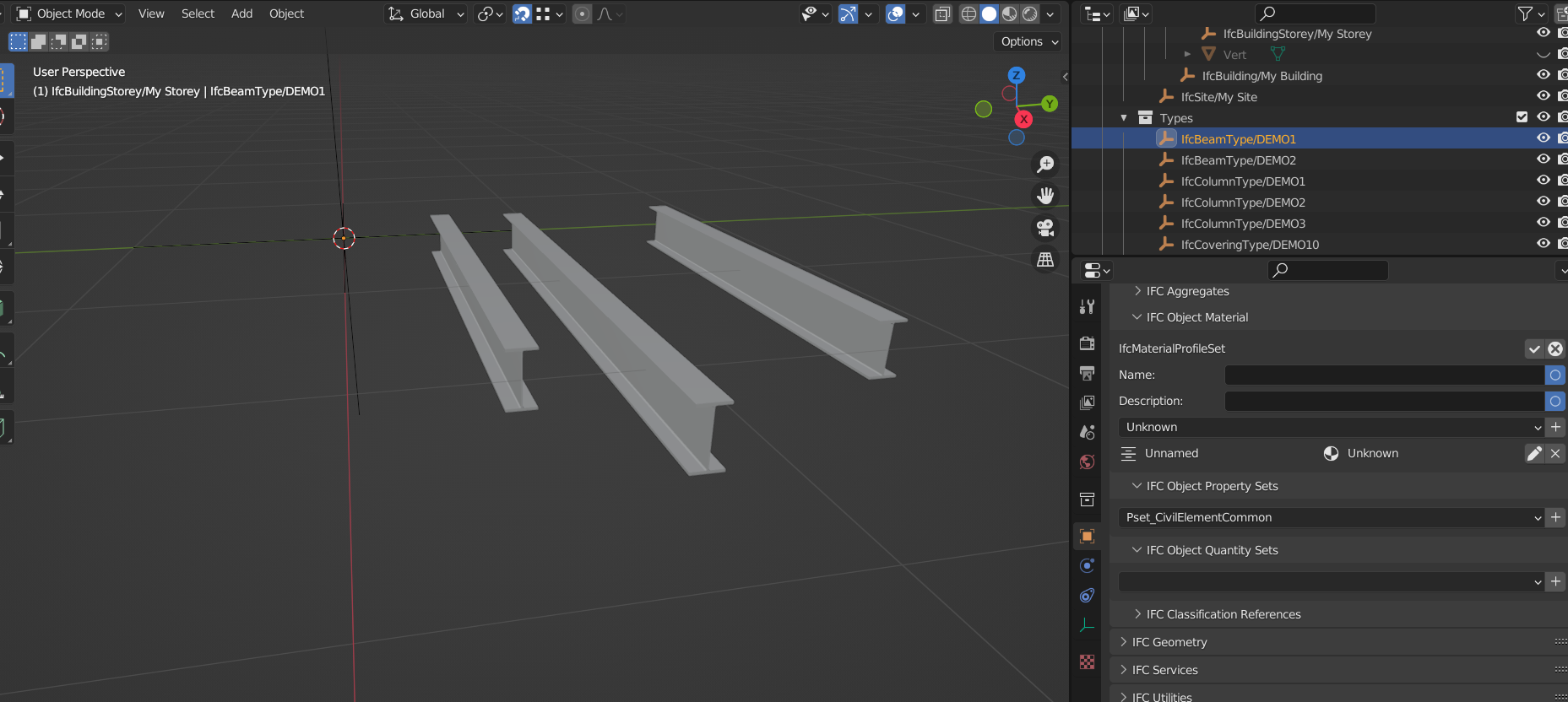
1) When I add an IfcBeamType
Ainstance, it creates a profile2) When I add another different IfcBeamType
Binstance, it uses the same rectulangar profile3) I tried creating a new profile, but I had no luck swapping the profile of the IfcBeamType
B.Anyone else ever tried it? I also can't manage to swap the profile of the IfcBeamType instances for a completely different Profile.
Bumping this thread for future reference,
I think it's possible to build a beam system with changin span direction and swapping profiles using an IfcSpace as a boundary perimeter.