

[IFC] an approach for dimension line offsets

related to...
- https://github.com/IfcOpenShell/IfcOpenShell/issues/1320
- https://github.com/yorikvanhavre/BIM_Workbench/issues/92
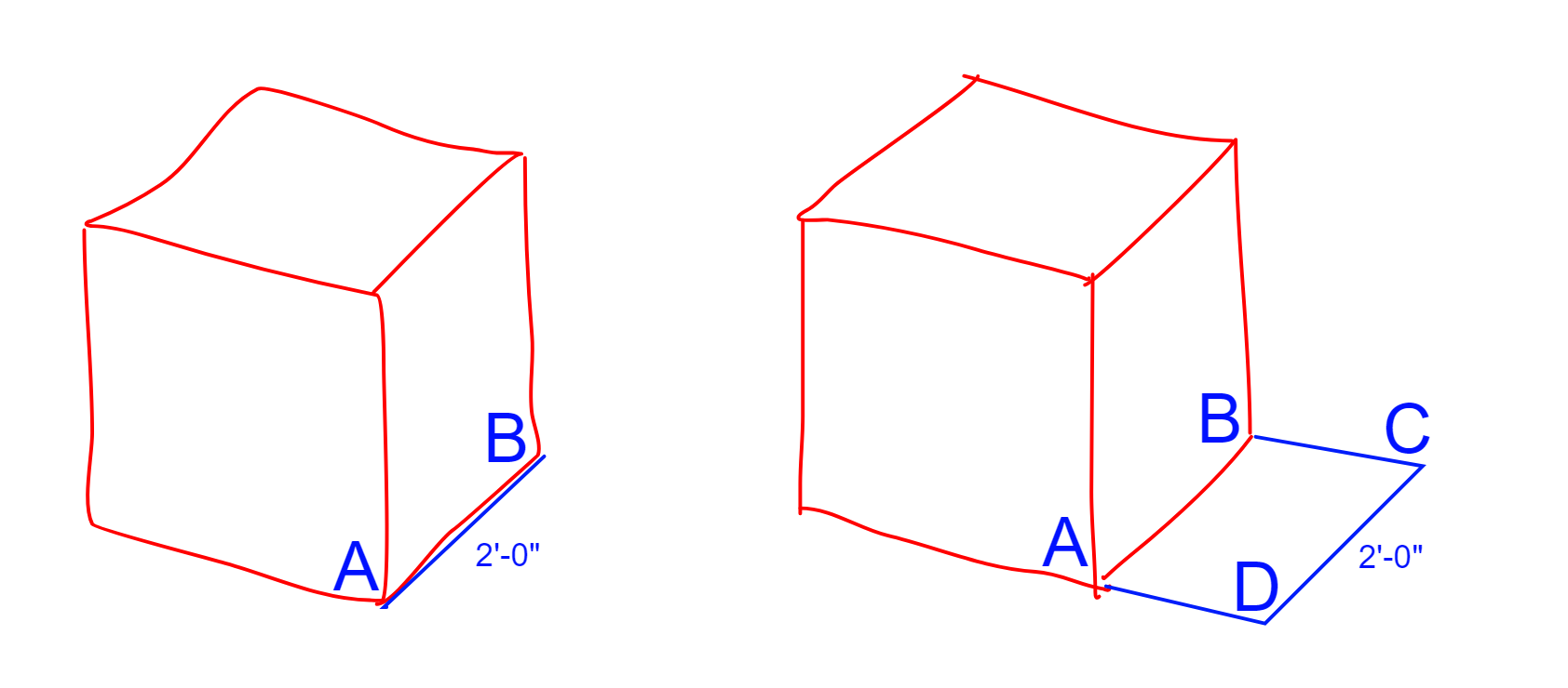
In FreeCAD, it seems there's a convention for offsetting a dimension string, from the points it's measuring. (cube on the right)
Currently in the BB, there doesn't seem a convention for offsetting. (cube on the left)
Created this thread to discuss ways to codify this offset into the IFC schema, if possible.
Any thoughts?

Comments
In FreeCAD a dimension is defined by 3 3d points + 1 direction (normalized 3d point): Point A and point B as on your diagram above, then point C is a point through which the dimension line must pass (this is how DXF does it too), and the the direction point indicates in which direction the line must go (this allows to do horizontal or vertical dimensions even if A and B are not aligned). But the ABCD schema above works well too, we could totally adopt it.
I guess what we need is a set of 4 properties, what about something like this:
Dumb question, could we embrace something like ezdxf?
https://ezdxf.readthedocs.io/en/stable/tutorials/linear_dimension.html
That is, either create new ifc entities, or ifc property sets that mirror the entities in ezdxf? No need reinventing the wheel.
Since this library is in Python too, could it not also be used in FreeCAD and BB?
ezdxf is basically a DXF read/write module for Python, so your question could be reformulated as: could dimensions data be stored in DXF format? I guess yes, but with no real advantage (DXF format, alhough it is just text, like IFC, is annoyingly cryptic and not very human-readable), it would in any case be a hack, not much better than the one I suggested above..
The real, proper way to do this the IFC way would be to use real IFC entities such as IfcCartesianPoint to define our points. But there is AFAIK no way to link to an IfcCartesianPoint from an ifcPropertySingleValue..
Sorry for the confusion, I wasn't advocating that it's stored in ezdxf or we use the DXF format, but to essentially codify the structure of the methods in ezdxf into the IFC format. That is, use exdxf as a template of sorts, or a roadmap, on how to structure dimensions into newly proposed IFC entities.
One thing is really nice, it's the ezdxf documentation... https://ezdxf.readthedocs.io/en/stable/dxfentities/dimension.html and even better https://ezdxf.readthedocs.io/en/stable/tutorials/linear_dimension.html#tut-linear-dimension
Just thinking outloud. Perhaps codifying the following method
into something like this...
This is how BlenderBIM currently codifies a linear dimension.
The above example is not totally correct, but hopefully you get my point. :)
or resurrect killed IfcLinearDimensions ;)
https://standards.buildingsmart.org/IFC/RELEASE/IFC2x3/TC1/HTML/ifcpresentationdimensioningresource/lexical/ifclineardimension.htm
Yes, that might make more sense! :)
It's not like the concept didn't catch on a little.. https://github.com/search?p=2&q=IfcLinearDimension&type=Code
@aothms , @Moult ,
What's your thoughts about resurrecting some of these ifcannotation entities?...
https://github.com/BuildingSMART/IFC4-CV/issues/9
It seems it would make our job of how to standardize these dimensions, easier.
What you see here is all autogenerated stuff. It's very hard to actually get accurate measures on real usage.
My proposal would be to prototype it as a "Template". For ex http://ifc43-docs.standards.buildingsmart.org/IFC/RELEASE/IFC4x3/HTML/concepts/Product_Shape/Product_Geometric_Representation/Axis_Geometry/Axis_2D_Geometry/content.html
So, let's say something like
IfcAnnotation[ObjectType="LINEAR_DIMENSION"] -> ... -> IfcShapeRepresentation[...] -> IfcPolyline.
... -> IfcShapeRepresentation[...] -> IfcTextLiteral.
By creating a usage pattern like that you do not obscure the definition in an entity that requires compiled in support but rather rebuild it using a composition of already supported definitions. While enabling the same amount of standardization.
Ooh that's brilliant!
1) Nothing to change in the IFC schema, and
2) all our needed info is there (provided the polyline is made of 4 points)
I could implement that in FreeCAD right away!
These usage pattern concepts sound like a good idea.
Dumb question perhaps, how do i render something like the following into that svg diagram? Would like to play around with creating a concept for these dimensions.
@yorik should we accommodate things like continuous dimension strings? If so, the (4) point method might not be the best.
@theoryshaw I don't think so, because that would be the job of the application, to recognize these dims and handle them together. It's easy, basically look if points (A,B) of dim 1 = points (C,D) of dim 2, if yes those two should/could be treated as one continuous one. So nothing specific needs to be saved in the IFC file.
BTW in your schema in the first post of this tread, points B and D should be swapped so ABCD defines a continuous polyline.
Sounds good.
Would love to hear @Moult's thoughts as well.
In the roadmap, not sure if he envisioned offsetting dimensions with blender 'decorations', or with a blender curve with (4) vertices.
I took a wild stab at a 'template'. Markdown here, svg here.
I'm not sure where to keep these, so I just started a IFC_Templates repo on osarch's gitlab account.
Please feel free to modify, as this is my first concept template!
Very cool:
Some small comments:
More conceptually:
We need to figure out if this is enough. If you create decompositions on the element level similar to what they did here http://ifc43-docs.standards.buildingsmart.org/IFC/RELEASE/IFC4x3/HTML/concepts/Object_Composition/Nesting/Alignment_Layout/content.html You have a little bit more options to tag the parts semantically.
That way maybe it's also more straightforward to create dimension strings. Because you can just keep adding elements to your decomposition.
Also there might be more options to associate the various fragments to the parts they annotate. Not sure what it would look like though. Maybe something like IfcRelConnects with ConnectionGeometry defined relative to the host element. That way at least when the host moves it would be possible to trace how to update the dimension.
It would become a bit of a monster template though... If your proposal is sufficient then let's not overcomplicate :) Hard for me to judge.
That's great!!
I would also use LINEAR_DIMENSION (or DIMENSION_LINEAR, maybe there will be more types later like DIMENSION_ANGULAR) as ObjectType, so far everything else I've seen is in all caps.
Another idea: Add another optional IfcShapeRepresentation, that is an IfcTextLiteral, to specify a custom text. If that IfcShapeRepresentation is not there, then it is supposed the text must be the measurement of the segment BC of the polyline.
Just stumbled across this on youtube.
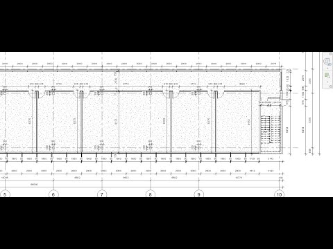
What a huge time-saver this would be for tedious tasks if this could be done in BlenderBIM :-D
@aothms @yorik Thanks for the suggestions! Have implemented them in DIMENSION_LINEAR.svg
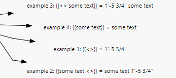
As you can see there, I suggested some approaches to overriding the text in the dimension string.
...
I took a wild stab at ASSOCIATIVE_DIMENSION_LINEAR.svg that uses IfcRelConnects with ConnectionGeometry. I have some questions there. Not very confident I got this correct.
...
@aothms I didn't know how to tackle the your suggestion to use decompositions. That part of the schema still confuses me a little.
Using point and direction might make it easier to reuse data, as there should only be a few directions in a normal, orthogonal building.