

[BlenderBIM] & IfcOpeningElements

This day I have been trying to use the Blender BIM add-on as an IFC creation tool, instead of an IFC authoring tool as intended at the moment? (please correct me if I'm wrong).
My aim is trying to find a fast workflow for cutting an IfcOpeningElement in Blender while using the IFC model as the single source of truth.
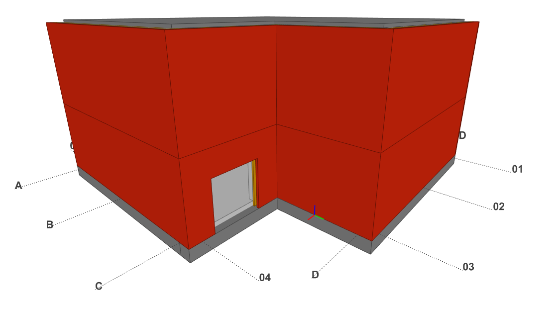
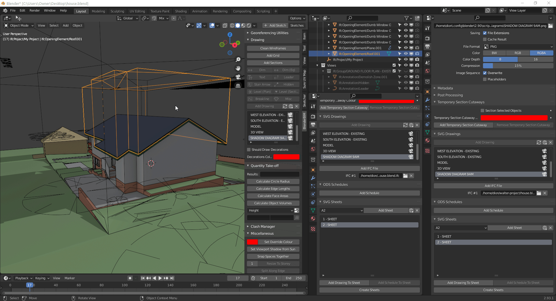
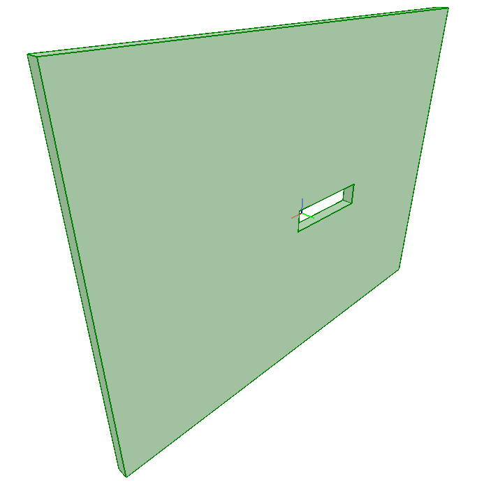
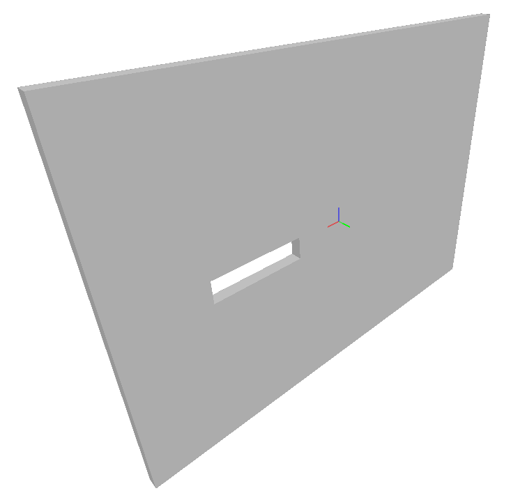
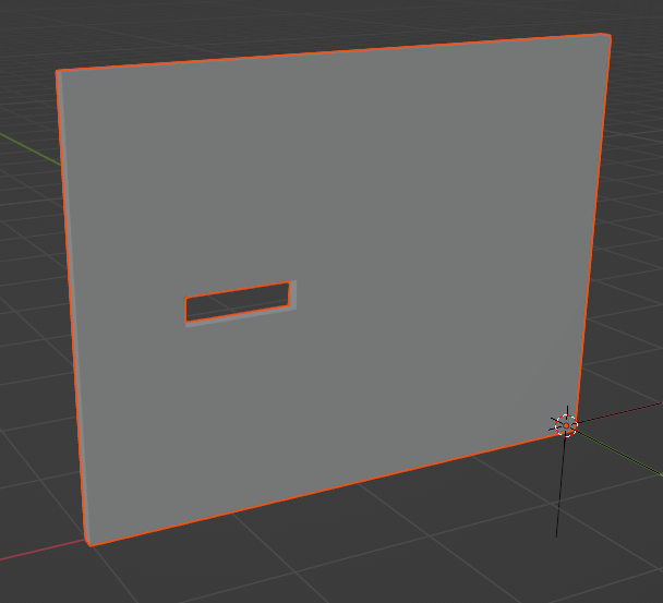
I have modelled a really simple cavity wall in Blender
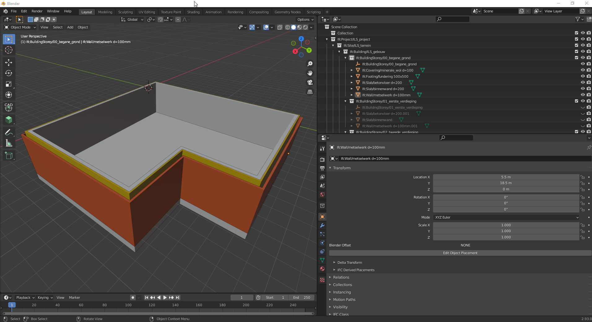
added a dumb opening from the Blender BIM add-on
Used the IFC Void tool to cut the opening
Exported it to IFC
I think you see where this is going.
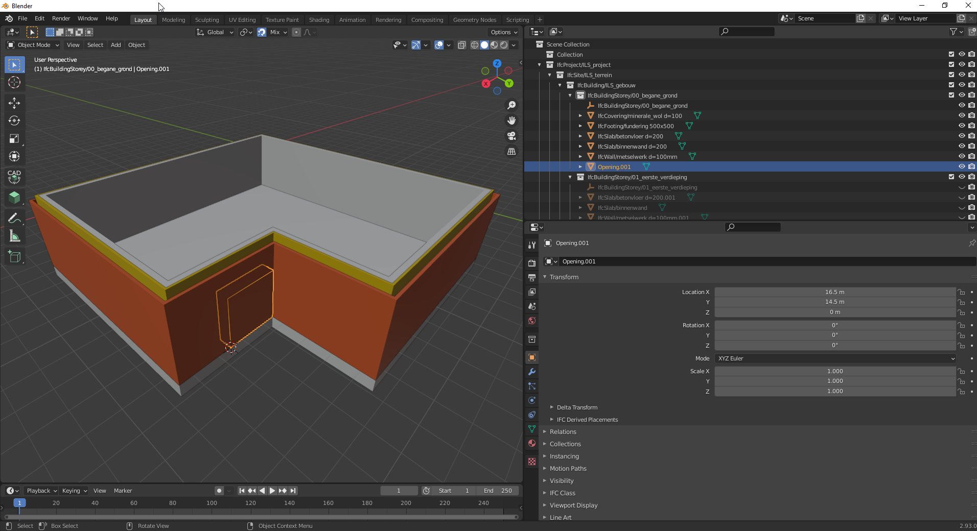
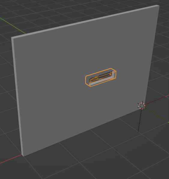
I need to add an opening for each wall, which is extremely time consuming.
However when I do this I can parent the IfcOpeningElements, so when moving them don't have to move them all three individually.
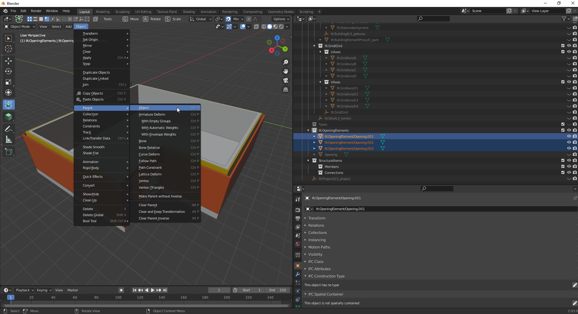
I moved the IfcOpeningElement 1 meter, it worked perfect when exporting to IFC
However. Very this method is very time consuming. I know there is Archipack PRO. But I was deliberately avoiding Archipack PRO because I want to use IFC as the single source of truth and not an Archipack or .blend file. Plus I use the parent-object functionality when importing the IFC in Blender again.
I have three questions:
1. Whenever trying to resize the IfcOpeningElements, I all have to resize each three IfcOpeningElements one-by-one. Is there a smarter/better way?
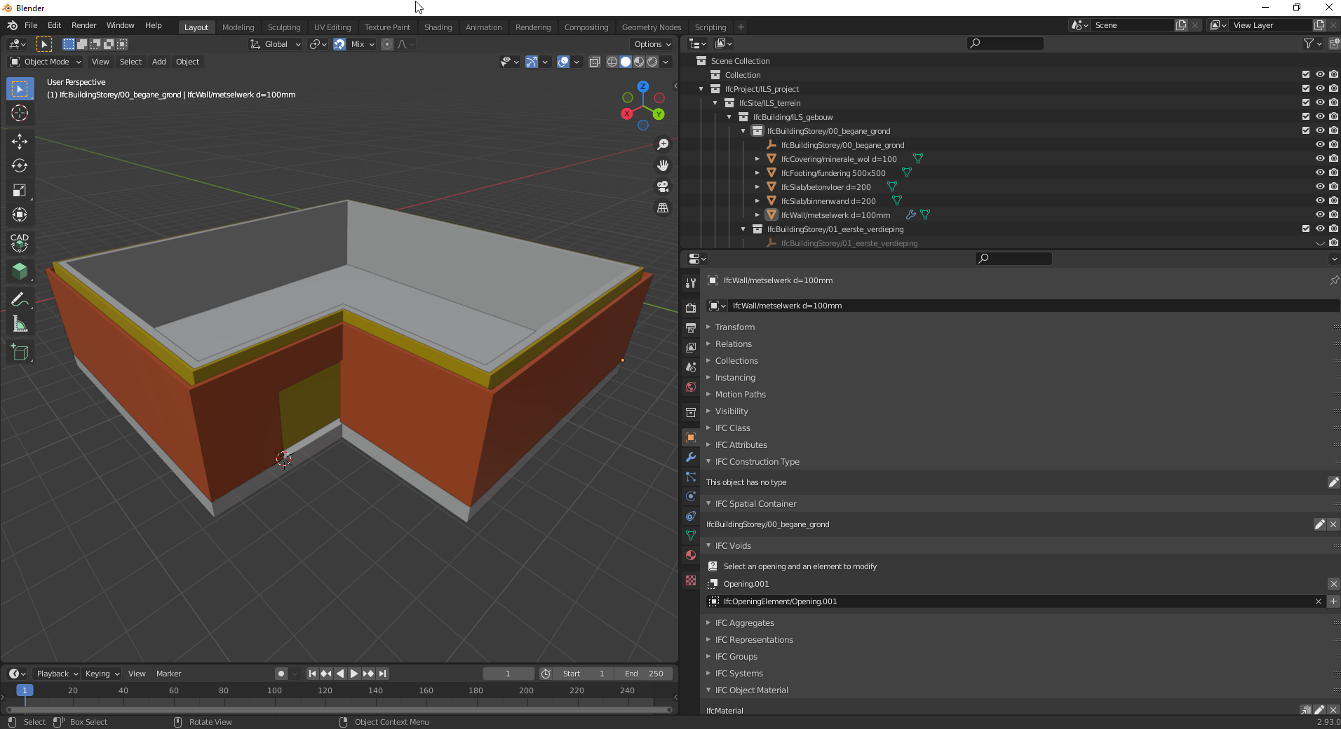
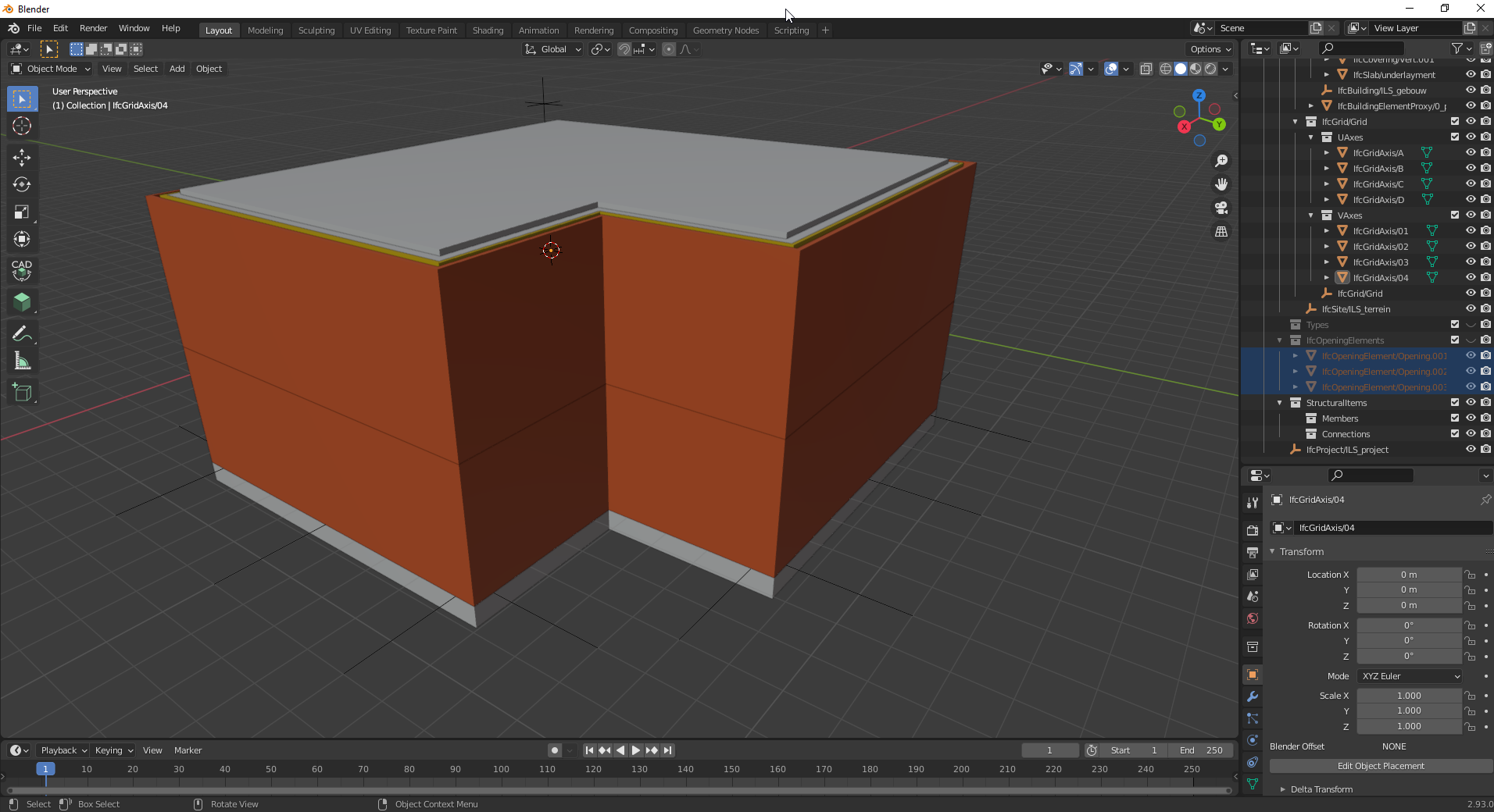
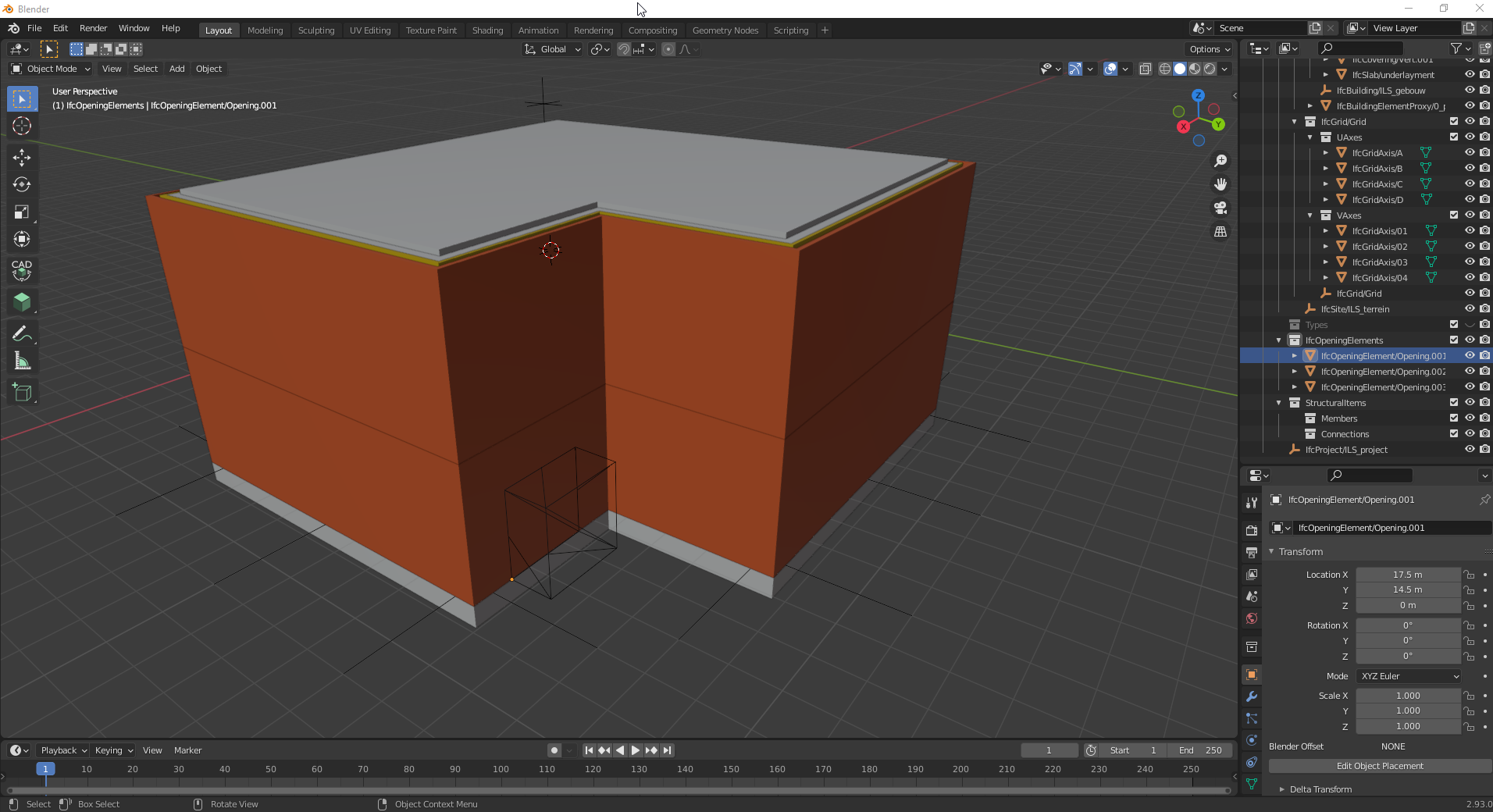
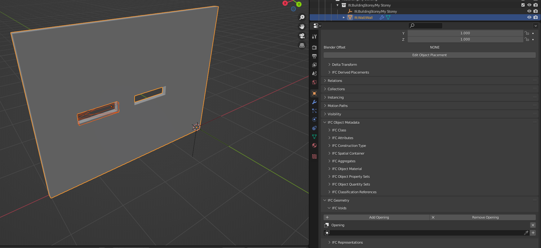
2. When importing the IFC again in Blender to keep the IFC as the single source of truth, I lost my Parent-object (obviously). But the BlenderBIM add-on automatically hides the IfcOpeningElements and does not show the opening:
Also when I click show opening, it does not show the opening in the wall while it's still there.
What is the reason for this?
- Do you have any idea or an approach for a fast workflow in Blender to use just one IfcOpeningElement to cut through multiple IFC elements? No idea if the IFC schema allows it.


Comments
Curious too. I would think you could apply (1) IfcOpeningElement to multiple walls. Maybe there's a schema restriction for this.
Look forward to when BB can visualize multiple layers of a wall, as discussed here. This would solve your problem, in part.
An IfcOpeningElement can only void at most one IfcElement (unless I'm mistaken)
Currently there is no way to achieve this workflow without using one IfcOpening object per Wall object. You may be able to link the mesh data so that any change in one of the opening objects propagates to the others but that may be it.
I believe the solution as mentioned by @theoryshaw is native managing of wall layers as mesh in a single object. But IfcWall is another beast with just the right amount of complexity that it's not really trivial :)
Or alternatively, but that would mean a lot of overhead on the blender side, linking a single IfcWall to several Blender wall objects and dynamically update booleans to propagate changes due to an IfcOpeningElement
It's unfortunate that it's only a one to one relationship.
I remember this project @Moult used an IfcOpeningElement to trim the tops of a bunch of walls to follow the roof line.
That would be handy!
But it doesn't seem like this is possible in light of the schema?
Yes, the void can only cut one object which I find pretty poor in IFC.
Let me ponder a bit on this and see what I can come up with. Perhaps @aothms might know a convenient way around it in the schema or another relationship we could use.
As for the last example, that trick worked because the walls were all one object - fine if you're modeling cowboy style in meshland, but not so fine if you want to follow the standard case convention where the walls stop at each junction. (Which is incredibly valuable for 4D/5D work, as well as parametric wall layers, so I sincerely hope buildingSMART never decides to discourage this convention).
For what it's worth, logged schema feature request. : ) https://github.com/buildingSMART/NextGen-IFC/issues/87
This has been discussed quite a few times within bSI. There's also quite a few people in favor of it. Other common examples are elevator shafts through multiple slabs for example.
The issue is that most people want to insist on the IFC spatial hierarchy from project > site > containment | aggregation > openings > fills to remain a strict tree (so every child exactly one parent except the root). And openings in multiple elements violate that. It's also problematic with the FillsElement relationship, which window can fill the opening if the opening itself is in multiple walls.
is it possible to use an alternative workflow?
the walls are modelled 'full width' then the windows are added and then the wall is converted to an internal wall, a cavity and an external/veneer wall but some software magic but of course the question is, can it then be simply edited add windows remove windows etc?
Just a thought
Also @theoryshaw, regarding your use case specifically, to be pedantic. This not what an opening is about. They are really for openings and recesses, not for clipping. That's what IfcBooleanClippingResult is for. So I think the somewhat unfortunate answer is that needs to be solved in the authoring tool with constraints between elements (modelled as IfcRelConnects e.g between wall and roof slab) and a bespoke "translation" to geometrical concepts. Due to the element-level isolation and other things, IFC isn't a perfect match to the design intent and constraints in an authoring tool.
Secondly, I must say that a clipping plane (IfcHalfSpaceSolid; the only allowed operand for IfcBooleanClippingResult) is a more natural way of defining the geometry than an arbitrary boolean operand. What if you weren't to move the operand, but want your roof slabs under a different angle? It's not a very semantic way of expressing your intent I mean.
And one more comment related to @Coen's original post. The way to model this in IFC is to have a IfcWall without representation (maybe an Axis) and then three IfcBuildingElement part objects with actual geometry. The opening is then associate to the IfcWall parent and the IFC implementations will apply that opening to all IfcBuildingElement part objects. I can imagine of course that also doesn't really map well to Blender's Boolean modifier, but perhaps some instancing and parenting makes it not entirely frustrating?
@aothms I assume you mean the empty Wall aggregates the Building Element Part objects.
Is there any particular rule concerning nested classes? Should the wall layers be Building Element Part or can they be Wall aggregated inside the parent Wall?
@brunopostle correct
It's a good question, the answer is a bit vague. The general principle up until now was that this was governed by concepts and model view definitions (and General Usage being some sort of encompassing model view).
Then you would have a concept such as Element Compositions that describes the general graph layout of composition and then you could have constraints on such templates, such as an IfcWall -> IfcBuildingElementPart.
So in theory this is exchange specific. This is what bSI is now trying to avoid and get tighter as such the freedom to arbitrarily constrain such concepts hinder interoperability.
Also, while the principles are there in IfcDoc and mvdXML, the authoring experience is quite limited and they have fallen behind wrt to the actual schema development.
So probably a good source of info would be to scroll through the implementation guide and implementer agreements.
If I look at the Element Decomposition concept from the latest version of the IfcDoc repo, this is what I can find, so it's not very complete.
@aothms I hadn't even heard of Wall Elemented Case, this spec has dark corners.
I'm glad to hear that an opening can cut assemblies, such as wall studs, and I have wondered how to do skirtings that span between doors.
Very dark, but all *Case elements are also deprecated, which shows how incomplete and not-up-to-date this mapping is I just showed.
A minor note about those reading:
Unfortunately modeling this natively is not yet supported in the BlenderBIM Add-on. We don't yet provide the ability to dig into the individual booleans of a shape representation with a nice modeling interface. Sigh, another one for the todo list.
But maybe that's also not necessary? I feel like it would also overcomplicate general cases. Perhaps you could somehow special case halfspaces in that it'd be a group with mesh and a plane or sth and in that special case during export they're folded into representation items. During import they're exploded into grouped elements.
Perhaps that's also a way out of @theoryshaw's use case. You just create a "Clipping Group" in Blender so that all elements in that group are clipped by the plane(s). It really seems possible to bidirectionally sync this with IFC. Although it's not fully "native" so I can see the problems there. Really just thinking out loud here.
related: https://github.com/buildingSMART/IFC4.3.x-development/issues/463
Completely sidetracking but thought it would be part of this convo,
I'm having a very silly problem which is probably just me not understanding how IfcOpenings work or voids generally,
but some of my IfcOpenings can be moved and some seem to create permanent holes in elements when exporting the IFC,
anyone know what I am doing wrong here?
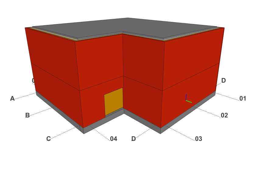
I've attached a file where the IfcOpening doesnt cut a hole when moving:
@Ace
Works for me, did you try adding the opening as a void?
1. Original IFC file
2. Original IFC file in BlenderBIM
3. Moving the opening and adding the openign as a void under IFC Geometry -> Voids
4. IFC in BIM Vision
5. Saved the IFC file and loaded the IFC file in a new Blender session
Ok brilliant, it's working hahah I just wasn't understanding the order of events, thanks @Coen !
@Ace
I also get confused sometimes, becaus BlenderBIM does not always load the updated IFC in my experience. So I keep BIMVision open next to it, where it promts to load the new file. And I click a lot of save project in between.
Did you click on 'Dynamic Voids' before moving the IfcOpening?
Video: https://www.dropbox.com/s/5tm6t7nzv7trh8i/2022-08-30_13-32-52_Blender_blender.mp4?dl=0
Ok brilliant! I tried using dynamic voids but again I think I was messing up the sequence and it wasnt playing nice thanks for this @theoryshaw
This long-standing issue is now resolved by the ability to void aggregates :)
I have one doubt: why is this a problem but then geometric representation can be shared among various products using mapped representations?
Well there's various answers you could give to that. IFC distinguishes rooted and non-rooted or "resource" entities. The representation is a resource and it doesn't have an "identity" and therefore from IFC's point of view, it doesn't make much of a semantic difference whether it is shared or not. Another answer you could give is that conceptually a model is multiple juxtaposed trees (containment/decomposition, type+geometry to element, material to element, ...). Or, as other people would argue, both are a problem. If we wouldn't have shared resources within a model we probably would have solved sector wide incremental exchanges for a long time already.
@cvillagrasa one thing I'd like to add is that the concept diagram for mapped representation shows how it should correlate with types. Therefore strictly the only time you should share representations is when it shares a type.
Of course, some people don't follow this rule...
Thanks a lot to both! @Moult ok, so indeed the mapped geometry concept states that "elements may have a 'Mapped Geometry' representation that reuses the concept Product Type Shape".
I'm having one more doubt, though. @aothms I'm attempting to recreate your awesome IfcOpenHouse, from more than 10 years ago (btw, impressive to be building all of that in 2012!), and I'm not understanding something with the roof. In the cpp source, you say:
And the IfcRoof is created as an aggregate of two IfcSlabs, with both having a mapped representation pointing to the same IfcShapeRepresentation, without using types. And BlenderBIM correctly displays it. On the other hand, I tried not to use mapped items and just
ifcopenshell.util.element.copy_deepthe representation of one slab so as to achieve that strict tree hierarchy, but in that case BlenderBIM just shows empties for the slabs.I know the original IfcOpenHouse was designed in IFC2x3, and I'm using 4x3, but is there anything obvious I'm missing with what I've said?
@cvillagrasa is it possible to share your script and/or the resultant IFC?
Well, IfcOpenHouse was a learning exercise for me as well. And there are definitely things that could have been done better. I wouldn't take too good a look at it. I think equating mapped items with types is also still fairly recent and somewhat speculative. If you take a look at this file for example https://raw.githubusercontent.com/IfcOpenShell/files/master/acad2010_objects.ifc (but yes 2010 and autocad which is not really bim anyway) you see the stair railings all being mapped items within a bigger representations where non-uniform scaling is used to scale the structs to the correct depth. I think the community kind of moved away from this as it is rather unsemantic, but as there has never been a formal validation in place for adherence to these kind of usage requirements you also don't really know.