

BlenderBim - feature request - door and window schedule automation - discussion thread

I wasn't able to find a previous in depth discussion on this so I thought to create a thread to discuss thoughts here as a point of reference.
Large parts of the appeal of other BIM software is the ability to automate door and window schedules to some extent. I thought it would be good to start thinking about this for BlenderBim
This isn't as essential as some other tasks in my mind but is important in the long run.
So how I currently do door and window schedules is in Multiple steps:
step 1: create elevation camera in front of door or window
step 2: position and size camera in front of door
step 3: draw table /frame with the line tool
step 4: draw openings and swings with hidden line tool
step 5: draw dimensions with the dim tool
step 6: place text with the text tool
step 7: copy the camera to windows that have the same orientation
And we get something like this:
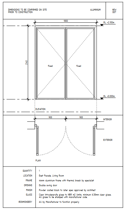
(Please excuse any shoddyness here)
And I end up moving the elevation tags out of the camera that are automatically created in plan views
It works but it's slow, my last project had around 19 unique windows and doors
Steps 4 to 7 I don't have a problem with they are pretty chilled. But I thought there could be some ideas to automate steps 1 - 3
Here's some thoughts for discussion / comment
1 - camera positioning and sizing
To select the window and automatically place and size a 'window and door schedule' camera-based on the window normal from the bounding box or using the front face position information and picking up the bounding box size and adding a 1 m offset
2 - linked door and window tags
Currently when I add an elevation view it has an elevation marker so why not link the window and door tags? The tag is in the correct position to begin with and it could streamline the process.
3 - a symbol as a table/frame for the schedule
Windows and doors come in all sorts of sizes but I primarily deal with doors and windows that are less than 2 by 2 m wide, I thought perhaps the table/frame could be a symbol like the door /window tag symbol and has preset text loaded like:
{{window type}}
{{window name }}
{{number of Windows}}
etc
I don't code (yet) so I'm not certain how feasible some of these ideas are but I thought I'd put them out there and maybe get some discussion around it.
This visual window and door scheduling tool could eventually be applicable for facade panel scheduling, for kitchen drawings, for joinery cutting lists etc
Hope everyone is having a great Friday! Obviously a terrible time to post this hahahha


Comments
Cool idea, how would one know on which side of the wall the camera is pointing? Could this be done with normals? I am not too experienced or knowlegdeable on this matter. I guess you would also want to make a window and door schedule from facing the exterior? How would this handle with internal doors?
I think there's two parts of this: a window/door types schedule, and a window/door occurrence schedule. On the projects I've worked on, the elevation/plan as you've shown is only for the types schedule, and the occurrence schedule is typically just a big spreadsheet. Therefore it's not actually appropriate to create many views pointing to different occurrences in the model. Instead, a single new drawing should be created, and a single occurrence of each type (or 2, one elevation, one plan) should be generated and laid out. Or am I wrong and are things done different around the world / on domestic projects?
I think maybe one of the 'normals' of the bounding box could provide a 'front' direction for the camera to face when it loads
Otherwise perhaps the info could be part of the window's or doors 'front' elevation if it logs that kind of information.
I think you have nailed it @Moult, there should definitely be 2 sets, the 1st being the 'types' and the 2nd being the big spreadsheet schedule
On small residential projects we typically just do the 'types' schedule which includes occurrence info like I've shown, but on larger projects these are split into the two schedules you've described so you arent wrong, although it may works differently elsewhere in the world.
That sounds great, how do you think we could get to this kind of layout?
Could see this 'drawing automation' functionality being used more agnostically. Could envision it automating steel shop drawings, or panelized construction, as just a few examples.
See attached pdf.
Pinging @aothms since he may have tackled a similar issue before.
The occurence schedule is pretty simple (though we can improve the UX a lot) since it merely involves an IfcCSV spreadsheet, and the existing schedules functionality. Just needs a bit more templating to make it more usable.
The types is a bit tricky. One option is playing uncontained occurrences of the windows and doors (or any element, such as truss, assembly, etc as @theoryshaw suggests). The occurrence is grouped into the same drawing group, but not part of any spatial container. However, this means that simple schedules which simply list all doors / windows would count extra things unless they account for the fact that some maybe uncontained (which is a bit unexpected, really). Similarly, we'd have to ensure they stay in sync with the thing you're documenting. With types with representation maps, we get sync for free. For occurrence only things (e.g. a truss assembly where the occurrences define the individual lengths of the members) it becomes tricky ... maybe solvable with some rel defines by objects relationships but I'd much rather search for a simpler solution.
Another option is to treat it as a special type of "IfcAnnotation" with an ObjectType of something special like "OBJECTDETAIL" or something which is then known to be replaced on the fly and/or shares a representation with the original. This is similar to how we have grid annotations or other drawing reference annotations (e.g. section symbols, elevation symbols) which "annotate" the original object (i.e. the drawing, grid, etc) and stay in sync.
Another approach is to treat these types of fabrication detailing to be a completely separate model. E.g. have another "fabrication / procurement model" IFC just for dealing with your door / window / assembly drawings so that your object counts don't interrupt your "as-built assembled model". Potentially this is more semantically correct and allows for additional detail that is relevant for fabrication or procurement that you may not contain in your as-built assembled model, like individual welds that you'd typically detail for steel fabrication. These two models can cross reference one another somehow.
Just brainstorming here,
Is it possible to link instances of IfcWindows and IfcDoors to a new Blender session? Or hide it away with a schedule collection?
Then you could "flatten" all the Window and Door instances on the Z-plane of the linked items so you will only need one camera view.
This way you could organize a sheet without touching the actual IFC model and because they are linked the sheets will be updated when you adjust the door and Window types.
Don't even know if it's possible.
Or maybe this is an extremely stupid idea.
@Coen actually that's a pretty clever idea of having a "Flattened" copy, because it makes me realise that you don't actually need the actual 3D body of the door or window or whatever. Most of the time, you're literally after a 2D detail from a very specific angle (e.g. elevations and plans for doors, or face normals for panelised coverings or steel detailing). So rather than having to create all these 3D doors which have to face the camera or be cut by the camera, another option is to have a "generate 2D annotation" which is linked back to a 2D annotation view, or generates an actual cut of the object that you can then tweak to suit your detail. Then of course you can "regenerate" the 2D annotation. Kind of like how in Rhino you might use the
Make2Dcommand.Therefore you can 1) not double count IfcDoors/etc since you will create an IfcAnnotation 2) you can easily generate cuts or elevations of anything generically for a "Detail View" (in Revit speak) and 3) either purposely deviate / override from the original (useful if the detail has to include things you don't want to model) such as multiple variations of door frame depending on the fixing detail to different walls or resync from the original if you make a change that you want to propagate.
Little experiment, I just duplicate linked each IfcWindow in the Schependomlaan, and it worked.
How would I go about flattening all the linked items? I would have to rotate them all 90 degrees. I think we can safely assume doors are always 90 degrees vertical?
My best attempt at linking Duplicates from all the IfcWindow instances from one level from the Schependomlaan.ifc using the align tools.
@Coen alignment is relatively straightforward because in IFC the rule is that the +X must be along the window/door/wall and +Y must be the normal of the window/door, and +Z is up. This is one of the little things that IFC does that people don't realise just how useful it is: it standardises various axis orientations.