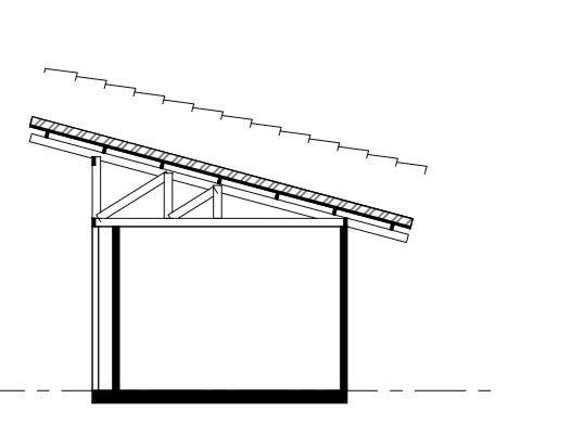
Hi guys, how can I configure the section to ignore the body representation of an object and show only the section_view representation? Is that possible? In my case, I have a roof that is modeled as a box, but I would like to show only the tiles in the section drawing. I have successfully created the tiles as lines in the section_view representation, but the body representation is showing and overlaps it. In the image below, I placed the tiles a little higher just to see if it was working.
This is the way it is in a typical door...
If there's a Plan/Body/PLAN_VIEW context it doesn't show the stuff in the Model/Body/MODEL_VIEW context if the target view of the drawing is PLAN_VIEW... or so i think it works this way. :)
Thanks! So I guess we should use annotation when we want to add something but preserve the body representation, like you did with the door swing. Is that correct?
Using Model/Body/SECTION_VIEW is correct. Plan/Body/SECTION_VIEW doesn't work because it is a plan view (i.e. no Z axis) whereas you are in a section view.
The behaviour of contexts has changed a bit over time (and this is uncharted territory so we are still feeling our way through to figure out what works for all scenarios). I apologise for the confusion, hopefully this will clear it up.
A context (or specifically, a subcontext, you never use contexts directly) is made of 3 major categories:
ContextType (Model/Plan): Model indicates it stores 3D geometry using XYZ coordinates. Plan indicates it stores 2D geometry using XY coordinates only. Note that these are not global XYZ, these are local XYZ coordinates relative to the orientation of the object (i.e. the orange dot). So if the object is rotated, 2D XY may not be pointing exactly up.
ContextIdentifier (Body/Annotation/Axis/Box/etc): we'll focus on 2 here. The Body says that the geometry represents the body of the object. The Annotation says that the geometry further annotates (e.g. highlights/labels/directs attention to a particular aspect of the element) the element. So if you are drawing a plan view of a door where the door panel is wide open, that is part of the Body. However, the door swing arc in theory is an Annotation, as it merely annotates the clear extents of the swing and directionality. Similarly, the triangle symbol / arrows used for awning and sliding windows are Annotations. In your example, your geometry is of the roof tiles, which is the Body.
TargetView (MODEL_VIEW/PLAN_VIEW/SECTION_VIEW/etc): this indicates that the geometry is suited towards this particular type of view and should take priority.
(note there is also TargetScale but we don't yet support that, it's pretty self explanatory though, such as different levels of detail for different scales).
In drafting, we always draw the body of the object, and then draw the annotation in addition to the body. (e.g. first you draw the window, then you draw the arrow indicating the sliding direction of the window). There are additional rules that certain values are special in that they often use particular 2D symbology that is unique to those views that you won't typically find elsewhere (e.g. fire extinguishers have a symbol on a plan, but you'll never use that symbol in a section).
So for a given drawing, here are the rules followed:
First the Body ContextIdentifier is drawn. Then, the Annotation ContextIdentifier is drawn in addition.
If there are multiple Bodies and Annotations to choose from, the one with a TargetView that matches the drawing is prioritised. The MODEL_VIEW TargetView is the fallback.
In addition, we have a special rule that if the drawing has a PLAN_VIEW or REFLECTED_PLAN_VIEW, the Plan ContextType is prioritised over Model.
Let's see a real life example. Let's imagine we are doing a regular floor plan drawing (i.e. PLAN_VIEW). If we had all possible Body permutations in theory, this is the priority list:
Plan/Body/PLAN_VIEW (top priority, as you'd expect)
Plan/Body/MODEL_VIEW (fallback)
Model/Body/PLAN_VIEW (fallback again)
Model/Body/MODEL_VIEW (final fallback)
Same goes for Annotations, just replace "Body" with "Annotation". Here's another example for a section (i.e. SECTION_VIEW):
Model/Body/SECTION_VIEW (top priority)
Model/Body/MODEL_VIEW (final fallback)
Notice we never consider 2D things in a section view. There are a number of problems with 2D in sections and elevations that has led to this special third rule.
How do you get the 3D geometry of the door frame/trim to show up with the door swing in PLAN_VIEW?
I thought i could put the door frame/trim in Model/Body/PLAN_VIEW and have the door swing in Plan/Body/PLAN_VIEW, but it doesn't seem to work...
video: https://www.dropbox.com/s/jstu6gtipypeve9/2023-05-08_15-33-07_Blender_blender.mp4?dl=0
I'd ideally like to keep the frame/trim as 3D geometry, instead of making it 2D, if possible.
I guess it doesn't show in the viewport since the viewport currently only shows a single representation (add it as a feature request?). It shows up in a drawing though.
Anyone know the approach if you want to show something in MODEL_VIEW, but don't want to show it in SECTION_VIEW? I tried having a representation Model/Body/SECTION_VIEW with nothing in it, but BB balked.
Can I get 2d lineworks of a slab and a floor in a plan view
Yes, that should be standard out-of-the-box functionality. You're not seeing this when you print a SVG?
I understand the flow of plan annotations views. When I had two story building, and I add landscape elements like a patio which was at 0 and first storey was the slab was not seen in plan view
Can anyone provide an examples for the ?'s in the table below/
Was not 100% certain what use cases they would include.
All these contexts come as default when creating a new demo project in BB.
ContextType
ContextIdentifier
TargetView
Example
Model
Body
MODEL_VIEW
Full 3D shape of an object - the 3D geometry of a door or window
Plan
Axis
GRAPH_VIEW
An axis of a wall or beam
Model
Axis
GRAPH_VIEW
?
Model
Box
MODEL_VIEW
The overall bounding box of the 3D geometry
Model
Annotation
SECTION_VIEW
An up/down arrow on how window sashes work
Model
Annotation
ELEVATION_VIEW
A door swing indicator in elevation
Model
Annotation
MODEL_VIEW
Text or symbols in an Orthographic view
Model
Profile
ELEVATION_VIEW
Can use a profile, instead a void, to create a void for door or window for example
Model/Annotation/PLAN_VIEW is the same purpose as Plan/Annotation/PLAN_VIEW. It should have a higher priority, and the difference is subtle but technical. A Plan context only has two dimensions. A Model context has three. This means that if you ever have a sloped or angled object it allows you to represent it.
That said, I can't remember or think of why it's needed by default right now.


Comments
Hi guys, how can I configure the section to ignore the body representation of an object and show only the section_view representation? Is that possible? In my case, I have a roof that is modeled as a box, but I would like to show only the tiles in the section drawing. I have successfully created the tiles as lines in the section_view representation, but the body representation is showing and overlaps it. In the image below, I placed the tiles a little higher just to see if it was working.
can you share the file?
Yes, here it is:
I tried to add Plan/Body/SECTION_VIEW context but couldn't get it to work. Although I feel it should. Think there might be a glitch.
I was able, however, to get Model/Body/SECTION_VIEW context to work, see video here:
https://www.dropbox.com/s/1bseirq8v0e79qs/2023-03-31_15-27-20_Blender_blender.mp4?dl=0
This is the way it is in a typical door...
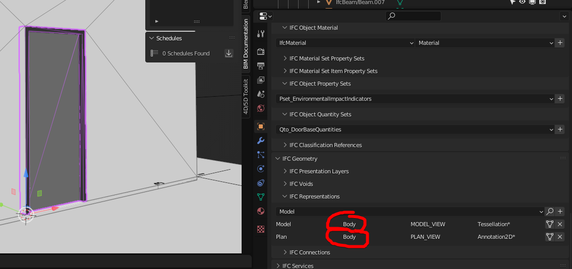
If there's a Plan/Body/PLAN_VIEW context it doesn't show the stuff in the Model/Body/MODEL_VIEW context if the target view of the drawing is PLAN_VIEW... or so i think it works this way. :)
Thanks! So I guess we should use annotation when we want to add something but preserve the body representation, like you did with the door swing. Is that correct?
i'm not 100% certain... contexts confuse me a little, still.
Using
Model/Body/SECTION_VIEWis correct.Plan/Body/SECTION_VIEWdoesn't work because it is a plan view (i.e. no Z axis) whereas you are in a section view.The behaviour of contexts has changed a bit over time (and this is uncharted territory so we are still feeling our way through to figure out what works for all scenarios). I apologise for the confusion, hopefully this will clear it up.
A context (or specifically, a subcontext, you never use contexts directly) is made of 3 major categories:
(note there is also TargetScale but we don't yet support that, it's pretty self explanatory though, such as different levels of detail for different scales).
In drafting, we always draw the body of the object, and then draw the annotation in addition to the body. (e.g. first you draw the window, then you draw the arrow indicating the sliding direction of the window). There are additional rules that certain values are special in that they often use particular 2D symbology that is unique to those views that you won't typically find elsewhere (e.g. fire extinguishers have a symbol on a plan, but you'll never use that symbol in a section).
So for a given drawing, here are the rules followed:
Let's see a real life example. Let's imagine we are doing a regular floor plan drawing (i.e. PLAN_VIEW). If we had all possible Body permutations in theory, this is the priority list:
Same goes for Annotations, just replace "Body" with "Annotation". Here's another example for a section (i.e. SECTION_VIEW):
Notice we never consider 2D things in a section view. There are a number of problems with 2D in sections and elevations that has led to this special third rule.
Thanks for the explanation, it's much clearer now
How do you get the 3D geometry of the door frame/trim to show up with the door swing in PLAN_VIEW?
I thought i could put the door frame/trim in Model/Body/PLAN_VIEW and have the door swing in Plan/Body/PLAN_VIEW, but it doesn't seem to work...
video: https://www.dropbox.com/s/jstu6gtipypeve9/2023-05-08_15-33-07_Blender_blender.mp4?dl=0
I'd ideally like to keep the frame/trim as 3D geometry, instead of making it 2D, if possible.
You can put the 3D geometry of the door frame in
Model/Body/PLAN_VIEWas you've suggested, then put the swing inPlan/Annotation/PLAN_VIEW.Hmm, didn't seem to work for me.
video: https://www.dropbox.com/s/5s4ys6wvu442cuu/2023-05-08_23-05-27_Blender_blender.mp4?dl=0
File attached
I guess it doesn't show in the viewport since the viewport currently only shows a single representation (add it as a feature request?). It shows up in a drawing though.
Anyone know the approach if you want to show something in MODEL_VIEW, but don't want to show it in SECTION_VIEW? I tried having a representation Model/Body/SECTION_VIEW with nothing in it, but BB balked.
@theoryshaw put it as part of the drawing's "exclude" filter?
Yeah, i could do that.
Can I get 2d lineworks of a slab and a floor in a plan view
Yes, that should be standard out-of-the-box functionality. You're not seeing this when you print a SVG?
I understand the flow of plan annotations views. When I had two story building, and I add landscape elements like a patio which was at 0 and first storey was the slab was not seen in plan view
is it a camera depth thing?
related: https://matrix.to/#/!ssOmSJysZpXBupsgjO:matrix.org/$iSKksTdlWTwtlBk-8rENgCJfwtAF-_i0Lf7awrAZKGc?via=matrix.org&via=fozyjoln.dedyn.io&via=infeeeee.duckdns.org
Can anyone provide an examples for the
?'sin the table below/Was not 100% certain what use cases they would include.
All these contexts come as default when creating a new demo project in BB.
Model Axis GRAPH_VIEW is presumably the axis of a column or member
Model/Annotation/PLAN_VIEW is the same purpose as Plan/Annotation/PLAN_VIEW. It should have a higher priority, and the difference is subtle but technical. A Plan context only has two dimensions. A Model context has three. This means that if you ever have a sloped or angled object it allows you to represent it.
That said, I can't remember or think of why it's needed by default right now.
Thanks.
Started a new 'representation context' page on our wiki: https://wiki.osarch.org/index.php?title=IFC_-_Industry_Foundation_Classes/Representation_Context
As usual, it's just a start. :)