

Small house design workflow with Open Source software (work in progress)
Currently I have the opportunity to develop some designs for a small building company. So I supposed I could try to use a real workflow with only Open Source tools during different stages of my work...
The structure of the workflow, for now is:
Concept design:
- One Floor Plan image
- General 3D renders images
Design development:
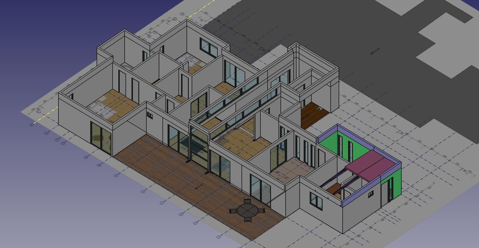
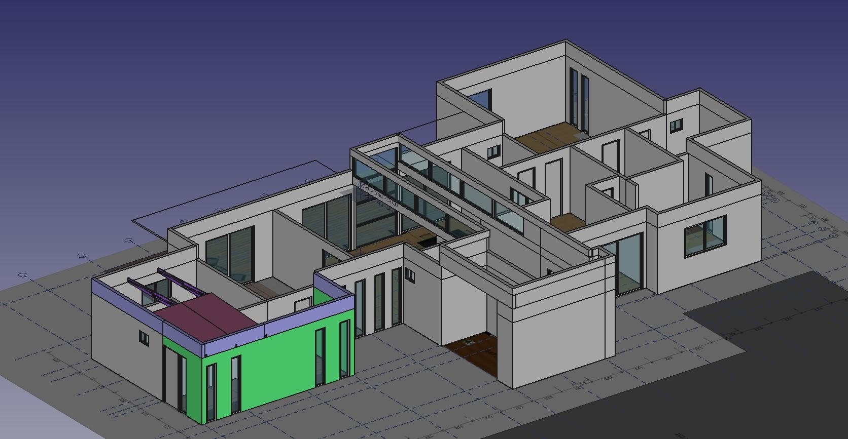
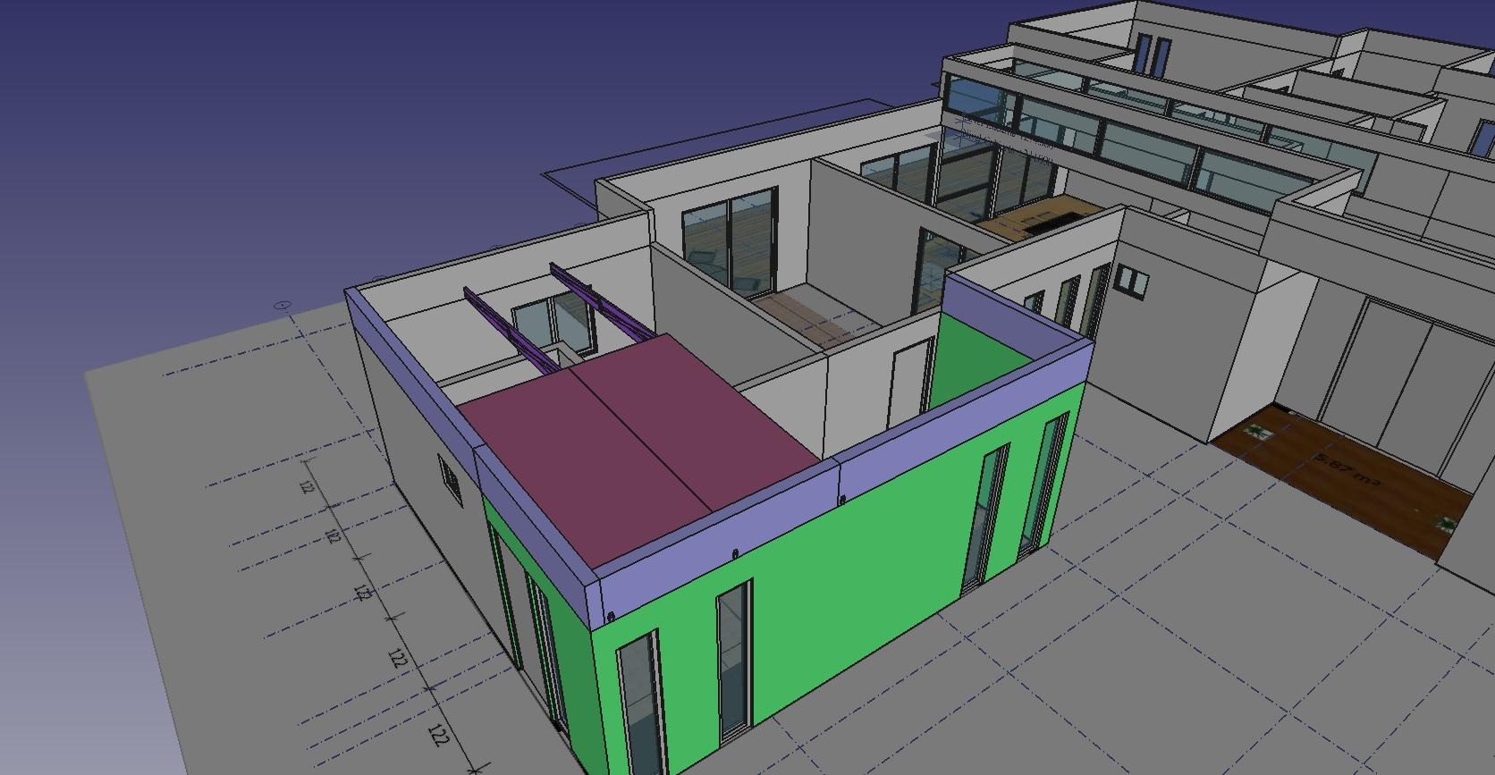
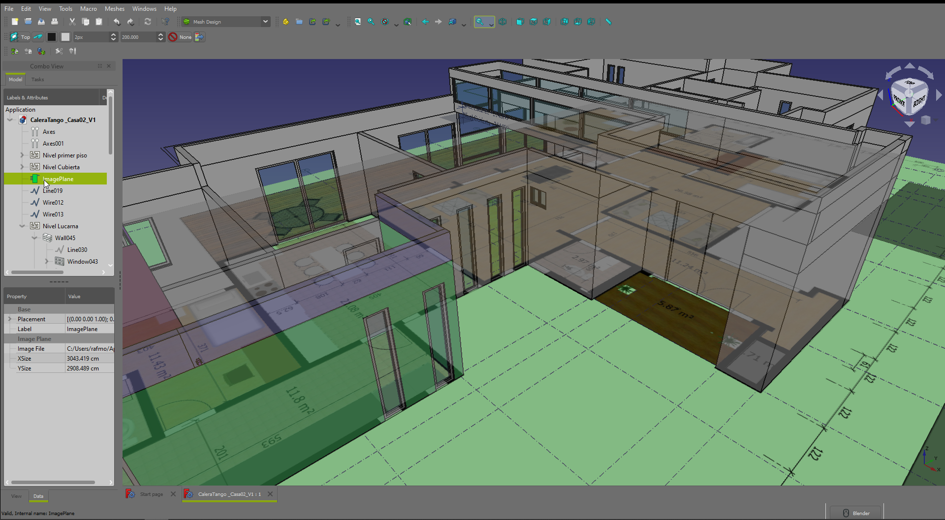
- 3D CAD model
Documentation:
- Set of basic Construction Drawings sheets
Results so far:
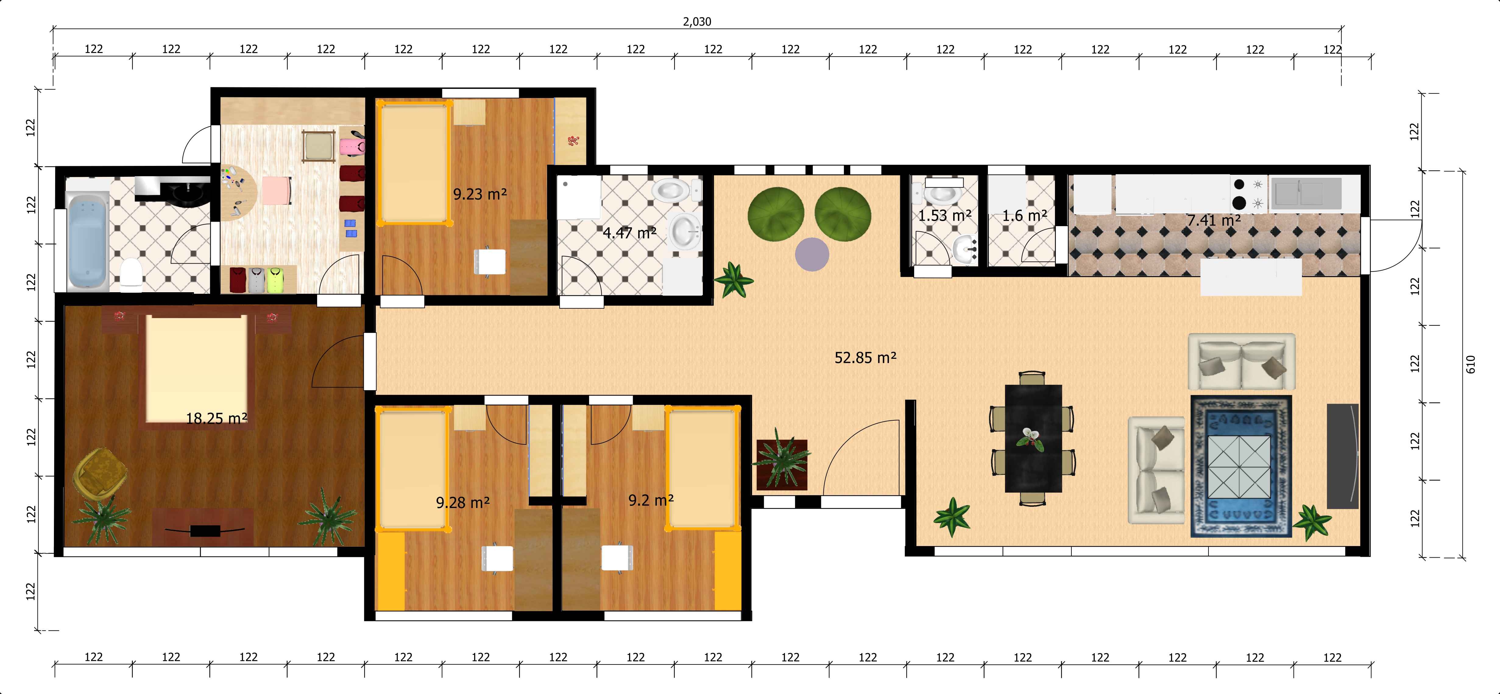
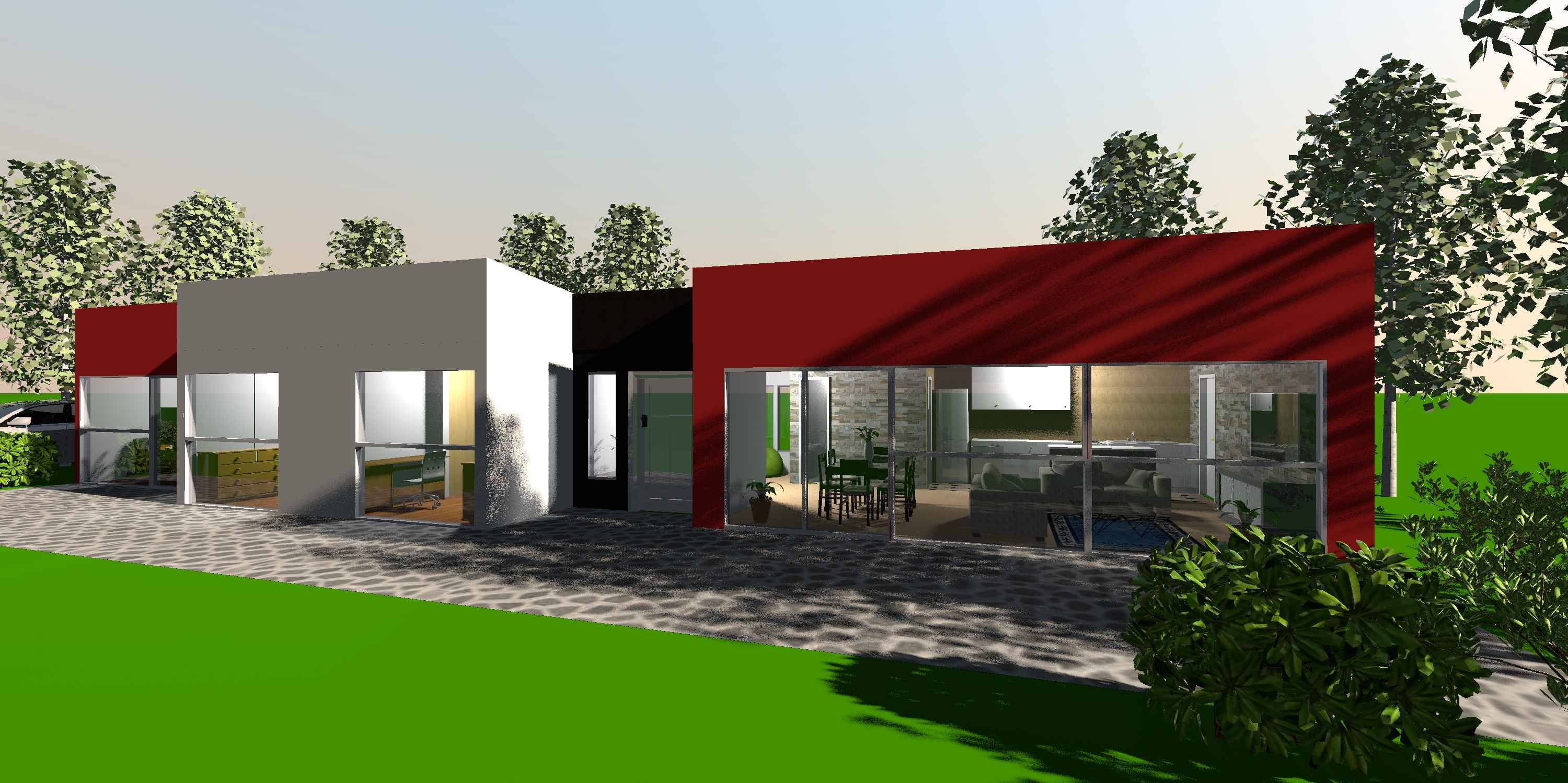
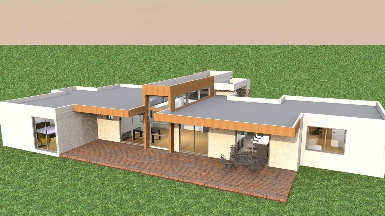
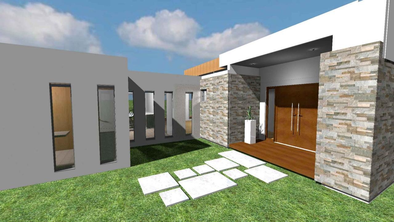
Concept design done with SweetHome3D:
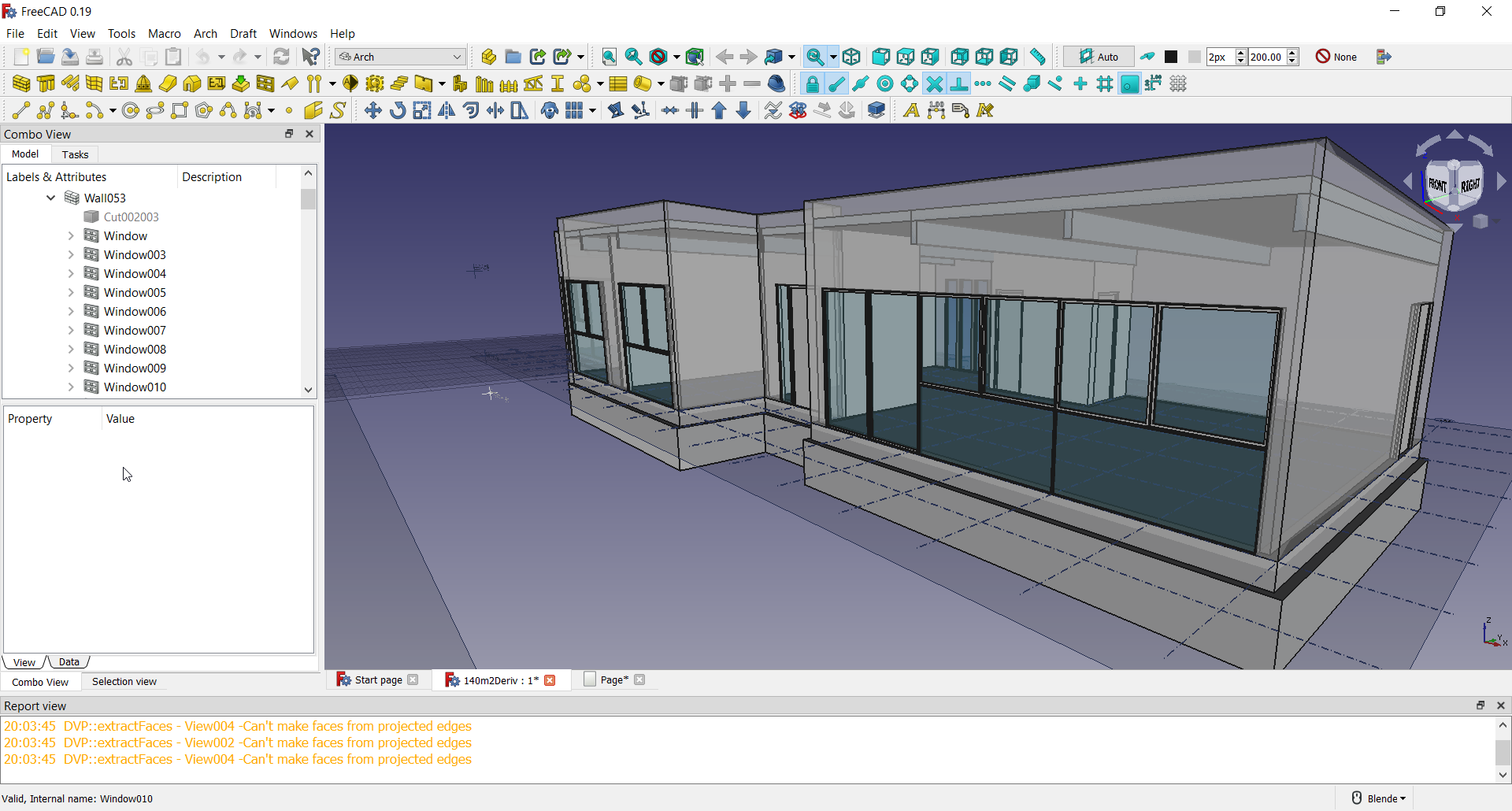
Design Development in progress with FreeCAD:
Documentation in progress with FreeCAD:


Comments
Great model and rendering :D
What aspects you find able / not able to do in FreeCAD / Blender ? e.g.
coloured texture floor plan
(so you did in SH3D right ?)
fast / sketch conceptual development ?
you do rendering in Blender right ? or SH3D ?
(BTW, trees are free models ? )
curious what you would do for documentation/ construction drawings and details ...
...
Thanks :)
p.s.
I haven;t worked through similar worflow for my test models like Villa /Savoye :D
Hi @paullee
The requirements from the building company are very specific: The idea is to build with S.I.P. panel technology, up to 140m2. They need to provide a concept design for each client interested, considering they personal requirements, as soon as possible. The thing is the majority of clients won't formalize a contract. Therefore, you can not dedicate much time and work in this first presentation, because if the client doesn't make a contract, it is not paid and there are more clients. Thus, I needed a tool to generate a comprehensible visualisation of a project for clients in a very short time.
With SweetHome3D I was able to create a floor plan layout of the house + furniture + internal renders + external renders in 2 hours.
The positive things of SweetHome3D:
The negative things:
And, yes. In this case, I used only SweetHome3D for the colored plan and the renders (no post-process with blender or Inkscape).
All the furniture models, including plants and trees are from the libraries of SH3D with free licence.
Once the contract is signed by the client I move to FreeCAD for a complete development of the design and documentation.
I did not use Blender in this first stage because it was not necessary a tool so sophisticated. Many of these clients don't continue the consulting after the first offer presented by the builder.
Also. I used a bit of Krita for sketching:
Thanks @bitacovir for the detailed explanation.
Haven't used SH3D, it seems it is quite powerful - but surprise with its various capabilities, it does not provide orthogonal elevations and section.
And indeed, I have difficulties to do coloured layout plan in FreeCAD. Maybe anybody has all those similar furnitures / plants objects in FreeCAD, and better still with textures (to be rendered on objects by ArchTexture ? ). And shadow is available but only on @Realthundar's branch / built.
Or peoples would output a Sketch Layout (generated from a sketch 3D model ?) to some graphic tools to add colour and texture ?
Any body has recommended software for this route ? Thanks :)
@bitacovir brilliant work! Great to see a practical example. Is using this software something you agreed on with the PIR panels firm? Could we name them? I'd like to add your example to our workflows on the wiki and why not link to the company.
Those are crazy thin walls! What climate are these for?
Sure you can use the images in the wiki.
This has been my personal decision. This company (the name is GoldemHome) is a very small and new one and not very sophisticated (it just started at the beginning of the year working on 5 houses, but only as builder. Then they contacted me to offer design as part of their service). They are a small team and use drawings on paper to build. Friendly people but their operation is quite simple and they don't care about my tools or workflow.
The walls show the thickness of SIP panels (140mm). The cover will be some polymeric material and it is not included in this preliminary drawings. We are in Santiago, Chile, with a Mediterranean weather (no snow) and the regulations allow thin walls.
@bitacovir Great! I'll add it to my list of things to do. Unless you want to add it yourself to https://wiki.osarch.org/index.php?title=Architecture_3D_models_created_in_FreeCAD
@bitacovir, Are you doing some analysis work? Like lighting or structural or CFD?
No right now. But I think structural would be nice.
Awesome @bitacovir ! i'm working on a project now (cannot reveal yet unfortunately) using mixed blender/freecad... it's really smooth to pass from one to another, there are even several ways, not necessarily ifc. i'll try to get some yummy structural stuff from the engineer :)
I would like to see the progress. But I won't be surprised on 3D work. Both program can manage very well that kind of task. The real challenge that I am facing now is how to generate and export documentation for authorities and consultants.
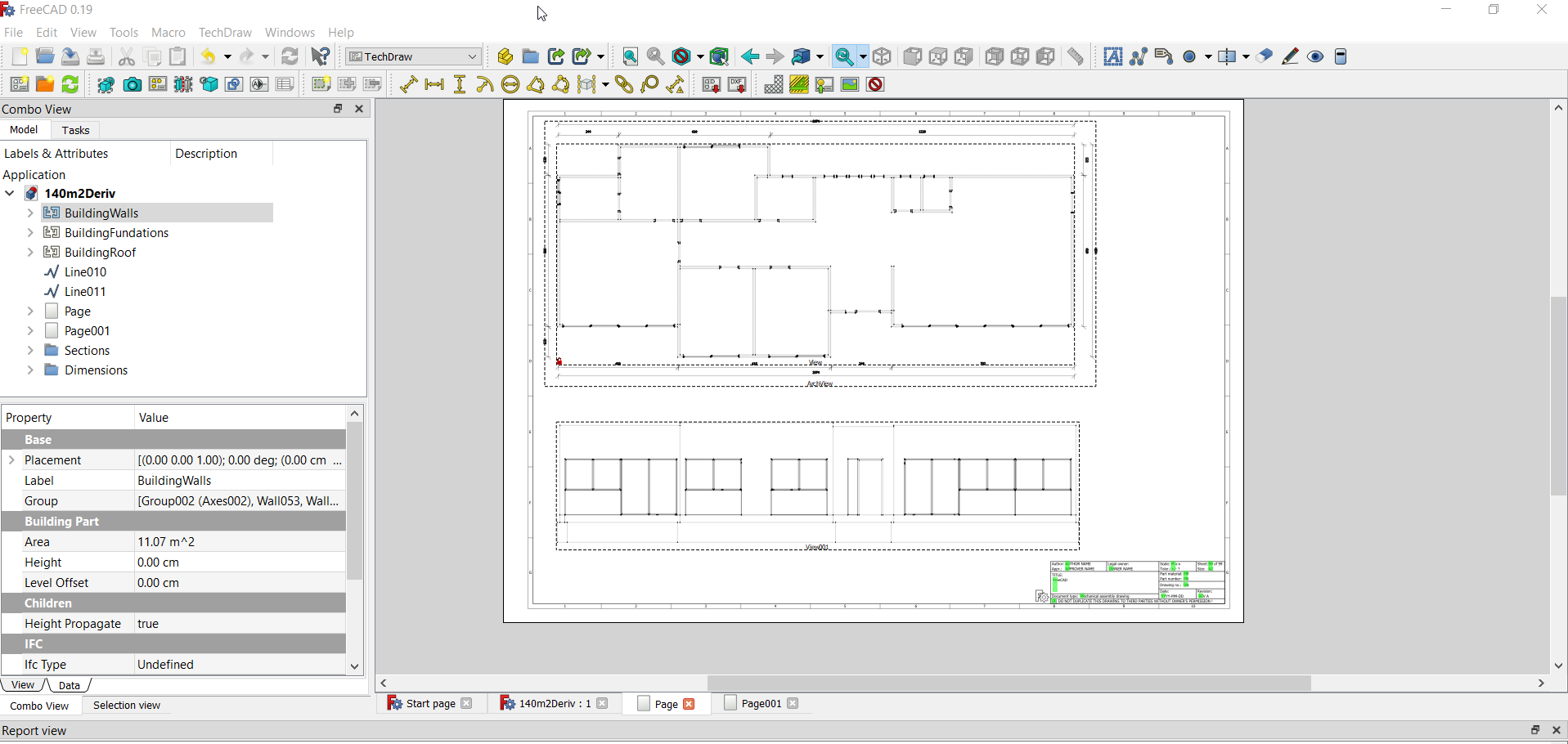
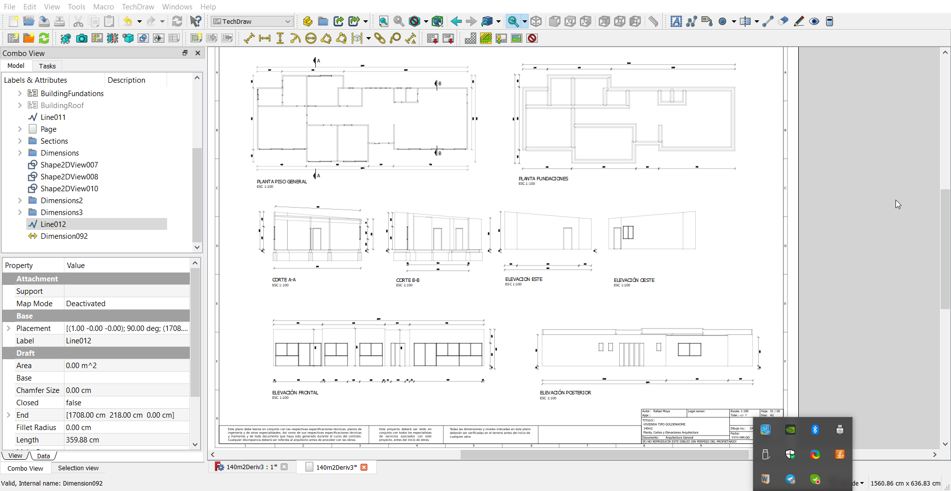
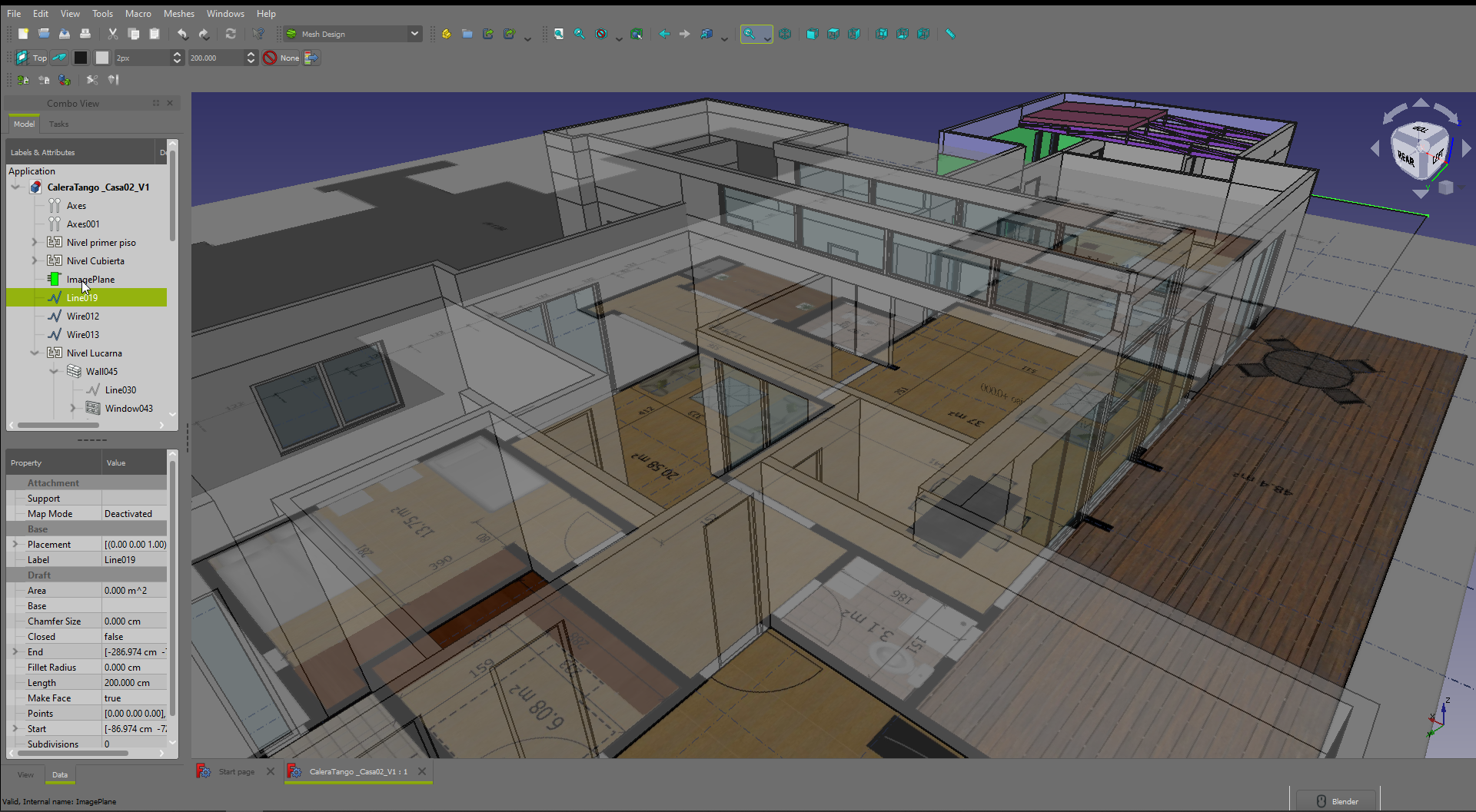
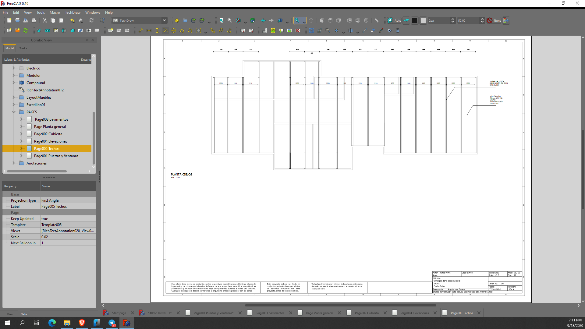
Here TechDraw WB in FreeCAD and an incomplete first drawing sheet A2.
@bitacovir so that's view of the model with added annotation? How dynamic is the annotation? Does it follow changes to the geometry, does it reflect object data (like Revit tags)?
This is the TechDraw Workbench in FreeCAD for drawing Documentation. For your questions: Yes, you can add annotations like dimensions to different views of the model. Yes, they are linked to the geometry, so if you make changes in the geometry, the dimensions are updated. However, this is problematic. The changes generally break the links and left dimensions as a mess. Therefore it is recommended to add dimensions once the design is finished. TechDraw WB was developed for mechanical design mainly. It does not have strong features for architecture design or BIM, yet. So, don't try to find many similarities with Revit. :)
@bitacovir are you just saying that the dimensions associations to geometry were not very robust? @yorik I'm very interested in associative dimensions. Is there an inherent problem in making this work in FreeCAD or is it just a matter of resources?
https://wiki.freecadweb.org/TechDraw_Dimension_Length
I think Yorik can explain better the current strengths and limitations of TechDraw WB.
@duncan I think that the main problem with every kind of association in FreeCAD is the topological naming problem: in short subshapes are "randomly" renamed after modifications, so if the dimension line went from Vertex1 to Vertex2, maybe after the transformation those vertexes get renamed, and the result is an unexpectedly messed-up dimension object apparently pointing to other 2 vertexes.
There is one main big effort to solve this problem in @realthunder freeCAD branch: https://github.com/realthunder/FreeCAD_assembly3/releases
Another example of FreeCAD workflow for Architecture:
Concept design with SH3D
Design Development with FreeCAD:

The topological naming problem may be solved in FreeCAD 0.20. But for the time being, you can add static dimensions using Draft Dimension, and just projecting that in the TechDraw page; this is the workflow that Yorik has been using for a long time. See TechDraw ArchView.
If anybody wants to help a FreeCAD user, see this: Collaboration on Freecad home project plans.
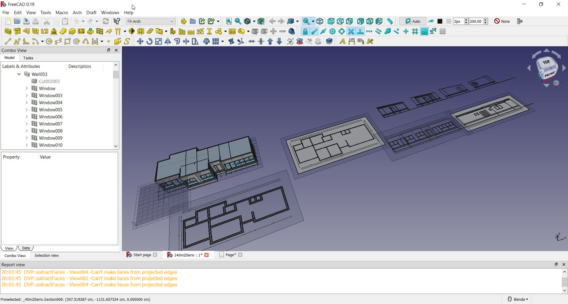
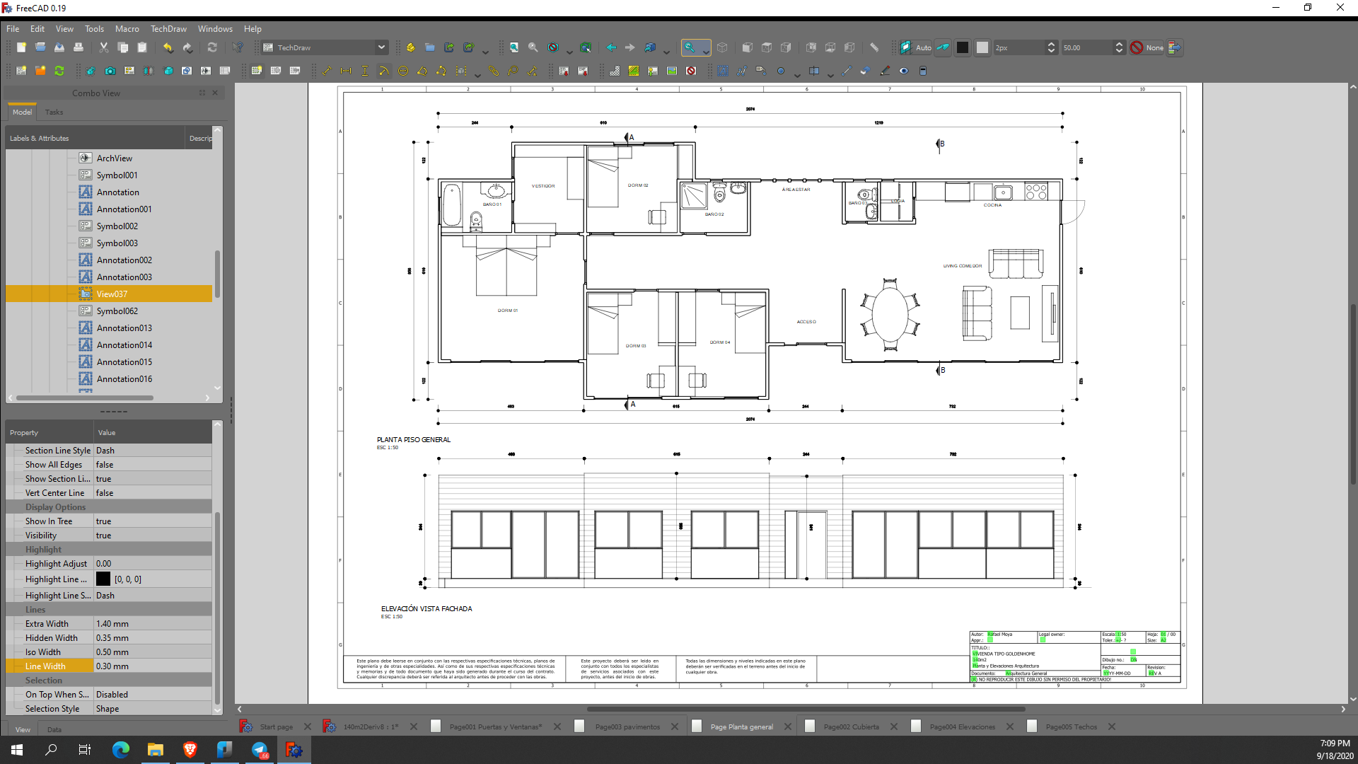
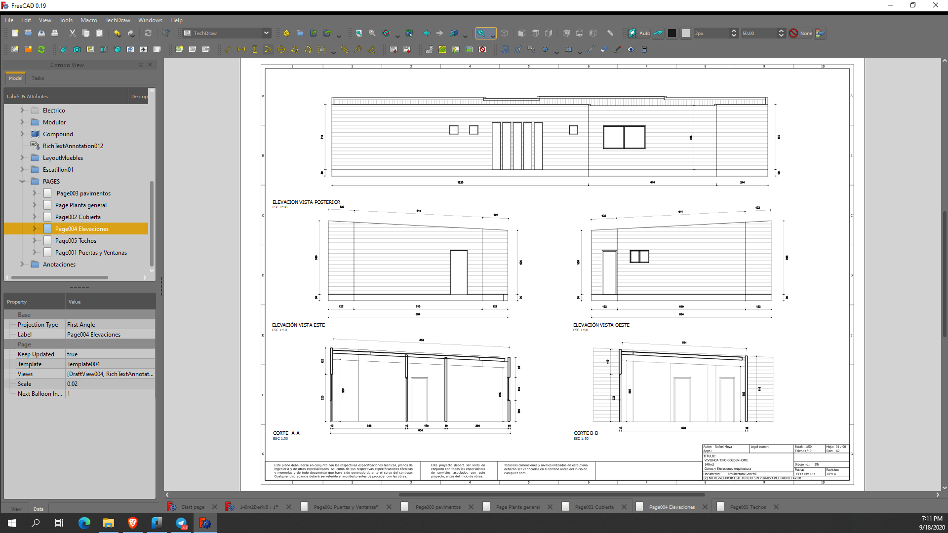
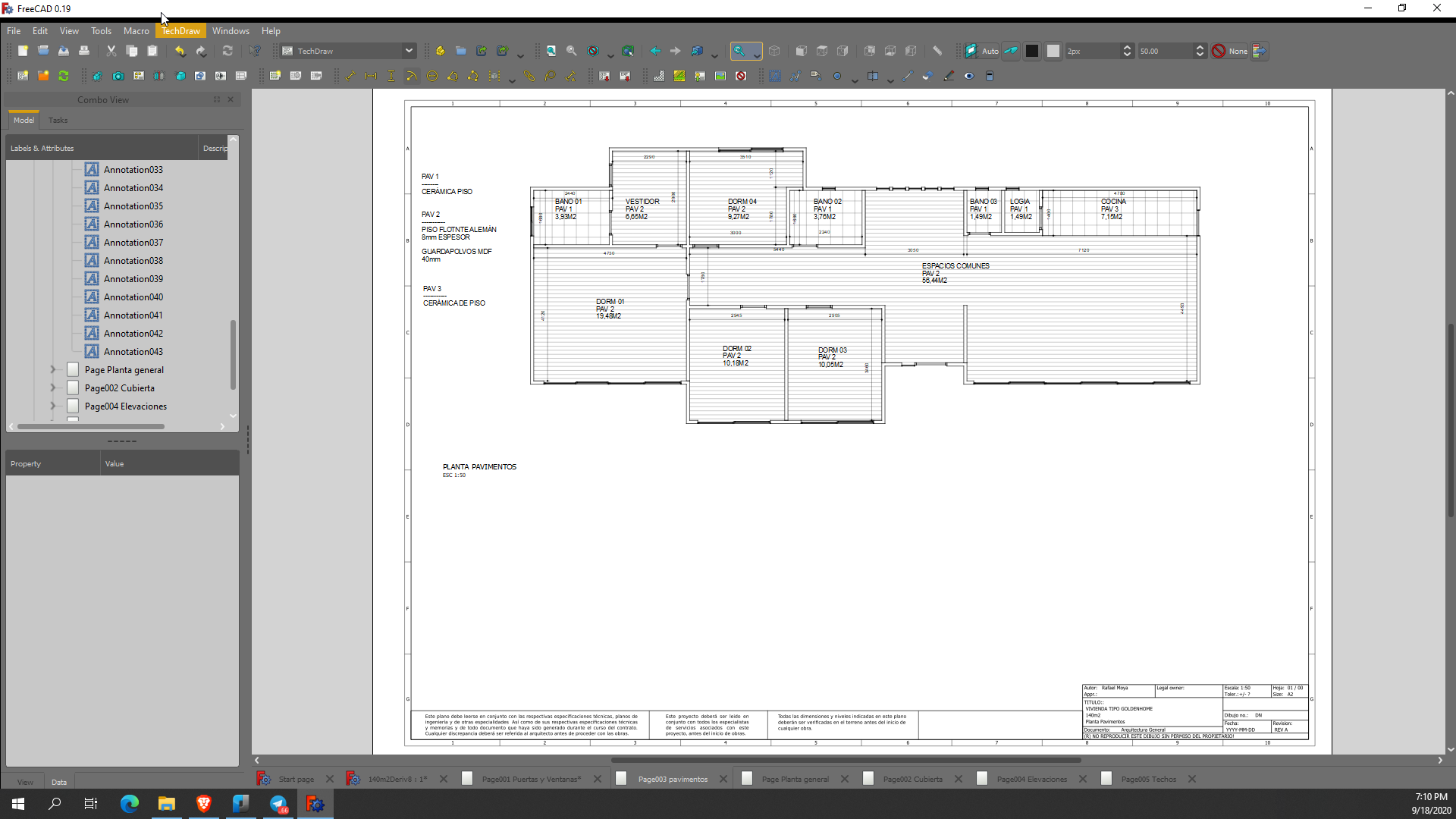
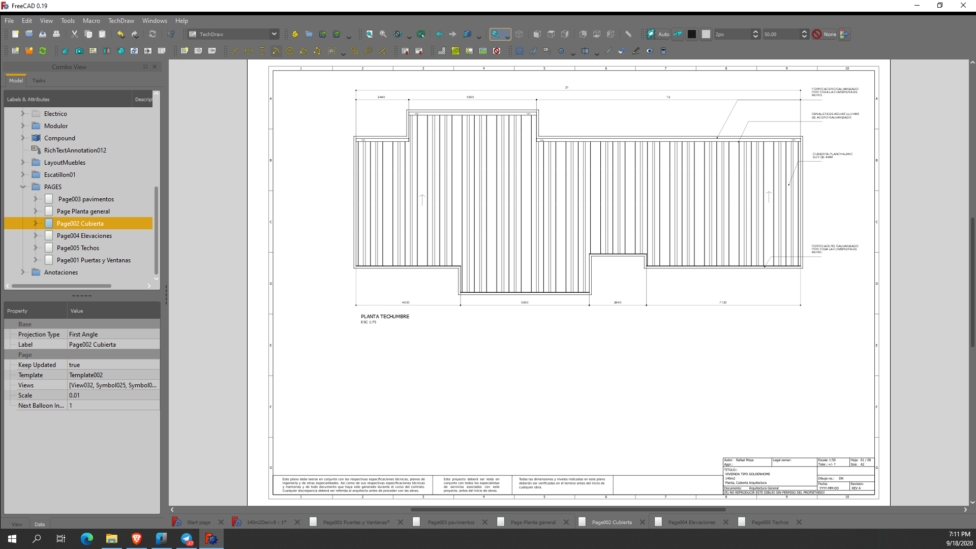
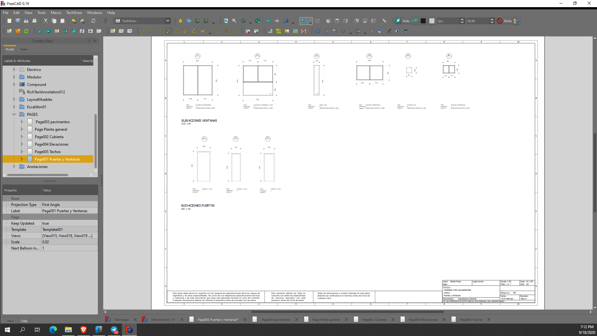
Here there are the final general drawings generated by FreeCAD and TechDraw WB for permits and authorities (the project is a standard model for mass construction, so no location is defined yet). Now, I exported DXF files and moved to LibreCAD for more detailed and constructive drawings.
Great project, interested to know your workflow :D
The above 6 drawings are purely output of TechDraw / FreeCAD, or edited in LibreCAD ?
Any view ondo editing in LibreCAD or InkScape ?
Thanks !
The screenshots are views of pages generated by TechDraw WB in FreeCAD. They are not PDF and there is not edition with LibreCAD or Inkscape. In TechDraw you can add texts, SVG symbols, and dimensions. Here I used a combination of Draft Dimension and TechDraw Dimensions. You can export PDF or SVG files with all the information from the pages. But if you want to export to DXF, only geometries are exported.
Positive :
Negative:
Thanks for the information !
Would like to see the completed project and documentations :)
For me the main issue with Techdraw is speed. It's too slow for large models like BIM models are. Note that this is mostly due not to techdraw itself, but to the underlying 2d projection algorithms of opencascade. Otherwise, it's pretty complete and doesn't miss much to have everything we wish. So basically the only real way i see for big speed gain is to get rid or bypass the OCC algo. One thing i started experimenting with is to derive a 2d view directly from the 3d view, but it is still not very stable. otherwise, realthunder also had some ideas to solve that problem...
That said, fantastic work you achieved @bitacovir !
But it is different thing at all. never was the same and has extra steps. Who developing opencascade?
I'm a bit more optimistic than that. We're running into the same performance issues https://github.com/IfcOpenShell/IfcOpenShell/issues/1153
Scattered throughout the ifcopenshell github thread there are lot's of things I'd still like to try for performance that are somewhat specific to our domain. For example:
@yorik Wonder any relevance between the discussion here about IFCopenshell and the Draft-Shape2dView workflow discussion in your last Sept blog https://yorik.uncreated.net/blog/2021-020-freecad-september ?
Thanks.
Yes, I was going to mention that too...
Basically we went further in bypassing the HLR step. What I'm doing more and more in FreeCAD is not put any 3D furniture in the model, but instead place furniture directly as 2D elements. Plus, we have the opportunity to use BRep geometry for sanitary appliances, which reduces greatly the problem (you can make a basin with 2 or 3 faces only).
It is somehow a workaround, but at least the user is still in control of the whole process, can turn things on/off inbetween, etc. And the simple fact of breaking the whole process into different phases (HLR first, building the SVG next) is interesting, only that has the effect to cut the overall rendering times in half (half the operations you do only require one of the steps to be ran again)
With these things, at leas for a small-scale project (a house, for ex), the rendering speed is now pretty good, enough for "real work", let's say. I'm working on a 8-appartment building too, then it's a bit annoying already, you need to turn some stuff off when working, but it's doable.
The "coin-based" solution we explored some months ago is not very reliable either, and doesn't give such a huge speed gain either.
Surprisingly, in FreeCAD, a step that takes time too is have the Qt graphics engine render the SVG... For a small one it's fast, but as it gets more complex, the rendering times goes up exponentially. But that might also be something easier to optimize.
I also think more and more like @aothms , what the "big boys" out there do is basically no different, they cache, they sort, they do stuff in the background, they cut the process into chunks...
Cool stuff man,
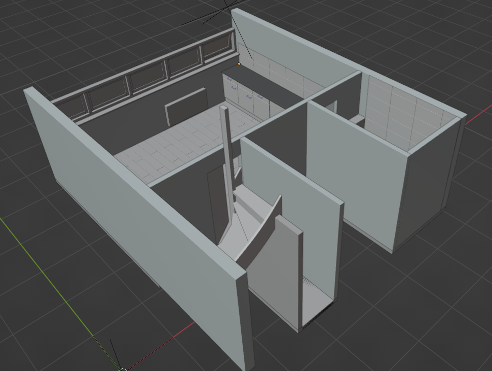
Here is my attempt of trying to model my own house from a Point Cloud using the BlenderBIM add-on.
I only use IFC as the main source (roundtripping). It's a painful process. haha.