

BlenderBIM: Have an IFC Dumb Wall roundtrip onto itself

Possible to have an IFC Dumb Wall roundtrip on itself in BlenderBIM? That is, recreate the 'solid' modifier.
Would love to see, as a general roadmap in BlenderBIM, that anything that is given added intelligence in Blender (through a modifier, for example), can be reconjured, upon the import of that IFC file into BlenderBIM.
Tagged:

Comments
That's the plan :) Actually, I think that it can be done natively with IFC's material layer set. Unfortunately, the BlenderBIM Add-on does not yet support the IfcMaterialLayerSetUsage feature in IFC - that is the prerequisite for this to work.
In the short term, I guess I can do similar to what FreeCAD is doing. @yorik - do you reckon there are enough similarities between basic Blender modifiers (solidify, array, mirror) such that both FreeCAD and Blender can use the same IFC Psets to record them?
Is there a 'tear' emoji?
:'(
Well I think we should rather look at it the other way around-what are the possible ways of representing geometry in ifc and what should they translate to in Blender. (I don't think there should be Blender- or even Blender plug in- specific data in the export , just to enable roundtripping.)
I can think of at least four ways people draw walls in Blender right now
-magic (archipack, plane with one modifier, controlled by parameters)
-axis with two modifiers
-plane with one modifier (btw @Moult what is the reason you picked specifically this option?)
-mesh boxes
all of which can be considered a standard. Will round tripping mean we have to pick some of these as our favorite and kind of force people to use them?
Roundtrip simple wall is only a first step, there are cases where "simple" extrude will not fit at all, eg wall under roof with slope on top of wall. For such cases (and many orther ones) only a geometric representation using polygons will handle properly all cases.
There is no easy answer :(
Even within IFC there are many ways to model a wall. At one point in time, buildingSMART picked a favourite of a 2D flat profile on the Z axis, which was extruded up and made an implementer agreement to use that (yes, this contradicts the IfcMaterialLayerSetUsage, which is perpendicular from an axis). They even created
IfcWallStandardCaseto attempt to enforce this. They have since realised that this was a bad idea and backed off.When faced with a difficult, non-standard scenario, my usual approach is not to overthink it and try things out and see. When things seem more successful, they tend to catch on, and over time organically grow into best practices.
I chose a plane with one modifier because it was the simplest non-magic method I could possible think of, and when I tried doing some commercial jobs with the BlenderBIM Add-on, that was my favourite method. Mesh boxes are painful when dealing with wall junctions, especially when non orthogonal. I didn't know you could do it with a single axis with two modifiers - can you show me how? I didn't want to do magic, since Archipack is already doing a great job, and I wanted to offer a non-magical alternative :)
This is what I use.
@JanF that looks much simpler than my solution! I've implemented it as a default in the BlenderBIM Add-on now: https://github.com/IfcOpenShell/IfcOpenShell/commit/dae5adc38b614c673c42fff50ea89daffd88ca46
I've left a boolean toggle (defaults to false) in case you do want a plane-based wall (e.g. if you are drawing a wall with sloping height).
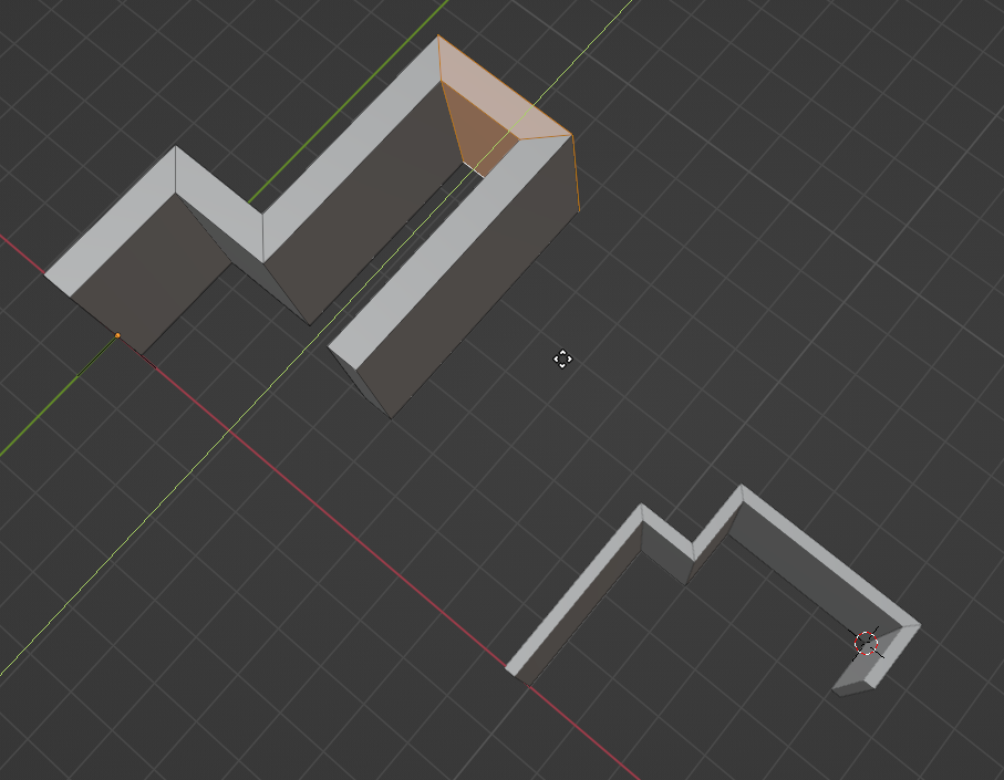
@JanF I might be missing something, but your suggested wall seems to be flared out at the ends.
Enable "Even thickness" in solidify modifier.
Btw. I learned this from Chris Prenninger (https://www.chrisp.zone/), he has some nice tips on parametric modeling in Blender.
Indeed there is a lot of similarity between freecad and blender bim workflows.. draw in 2d -> extrude/solid -> array is a very common one. But more and more I also like the idea that geometry is geometry, and each user (or app) sort of "chooses" how to edit that geometry. for ex, a wall drawn as a vertically extruded footprint in one app, might be edited another way (for ex by moving verts of a vertical face) in another app.. that is, the modelling history would not necessarily be imposed on you..
@stephen_l
How does Archipack roundtripping with walls work?
Has there been any progress on roundtripping a dumb IfcWall?
How would one store the wall width in IFC as a type parameter?
Yes, it has for some time now.
Check out these files.
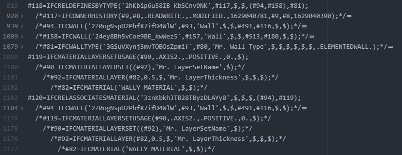
The following shows how the type info is saved...
IFC supports multiple layers, but currently BlenderBIM doesn't support it. As discussed here
@theoryshaw
Thanks for the answer, the reason being IfcWall can be defined in too many ways ?
as described by @moult in this post:
This makes me think, is it worth building functionality in BlenderBIM where certain functionality would only work in BlenderBIM because the IFC was made with BlenderBIM? This would really confuse users I think if they try to load IFC models from other software vendors and the functionality would break.
What's the fastest way of modelling an IfcWall and have the possibility to revise instantly?
With revising, I mean changing the width, length, height etc.
I now distilled two methods, which I call A and B.
Method A:
Uses mostly Blender functionality:
1. Start with adding a single vert
2. extrude it along the z plane.
3. Extrude it in the Z direction
4. Use Alt+LMB to select all the faces.
5. Use Alt+E to Extrude faces along normals and use offset eve
It's really fast, but the downside, It's quite a dumb wall, no possibility to roundtrip in IFC.
I can use the Blender functionality of Shift+G select coplaner to adjust the heights of the mesh, and export it to IFC again.
Also I can use the Alt+E method to adjust the thickness of the existing mesh and export it to IFC again, but there is no quick option to make the wall( technically the blender mesh) thinner.
Method B:
1. Load the IFC4 Demo Library on Setup
2. Go to the BIM Tool and press Shift+A
3. Go into Edit mode to drage the face of the wall
4. Set the 3D Cursor -> Origin to 3D Cursor
5. Press Shift+A again to add another type
I have to repeat these five steps for each IfcWall instance, extremely time consuming, but the upside is that I can adjust the width in an instance. And it's parametrized within IFC. Which is a huge benefit..
Does anyone know a faster way then I described here?
Also when I want to move a certain wall, method A is also preferable, because the mesh is one continous loop and makes it very easy to modify.
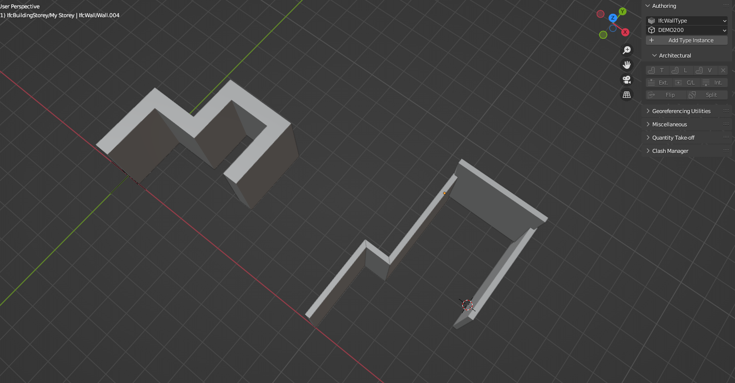
As shown here, is there a method to keep the walls joined/attached with an IfcWalltype instance?
I know I can select the walls and press the V again, but is there no way to keep them attached?
I prefer B, as it's roundtrips nicer and is on par with how a lot of other BIM programs work.
Yes, currently there's no way for the walls to stick together, if you move one, for example. But I think that fundationality could be added in the future... perhaps through geometry nodes, or hardcoded in ifcopenshell.
Also this future roadmaps would accommodate the
Priorityattribute in IfcMaterialLayer entity. That is, structuring how the various layers of a wall will intersect with each other... or with overriding the
Priorityattribute with IfcRelConnectsPathElementsI recently learned about the existence of selecting an edge loop -> alt + e or alt + s in Blender.
This way you can easily modify the mesh of a wall in any thickness you would like. It's al Blender functionality and nothing really smart in IFC happens. But could be useful for dumb quick fixes.