IfcTYpe Furnishing set for Plan

Hey everyone so I've been using BlenderBim a short while and have created a little design furnishing set to make 2d concept plans quicker
I made this concept guy as a showcase:
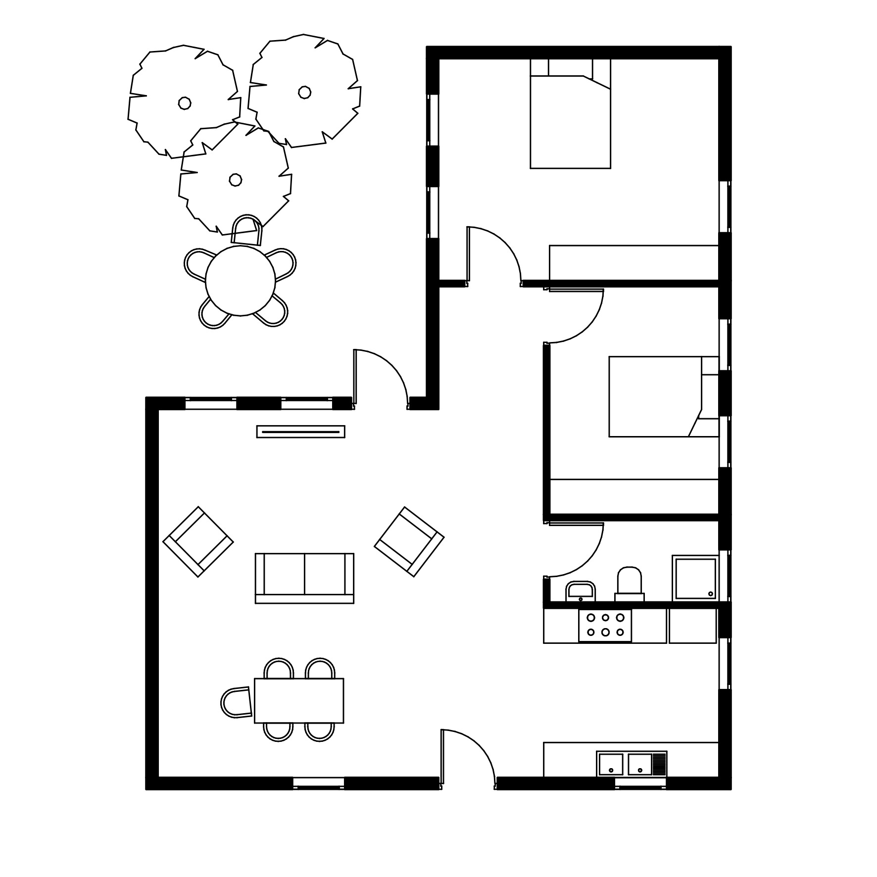
Here it is in mm:
edit: And I've also attached one that is in Metres
Tagged:


 and 2 others.
Comments
This truly is awesome. In fact one of the things I wanted to do for the next release is include an Australian residential pack, with stuff exactly like this. Are you trained as an architect? Which part of the world have you based these dimensions on? (e.g. here Australia has particular bed sizes for single, king single, double, queen, king, and we might look at Caroma for rough sanitary fixture sizes)
I wonder ... I wonder if we can contribute these "architectural" things to https://github.com/boltsparts/BOLTS so that FreeCAD / OpenSCAD can also benefit from these rough planning objects? Then we can turn your objects into a script we can then generate for libraries for different parts of the world and ship them with the BlenderBIM Add-on installation.
What do you think?
Sounds good, these are based on South African Standard sizes, I am a registered Architect.
I am busy making standard Aluminium window and door sizes too, so keen to put it all in BOLTS! If that's alright
https://github.com/boltsparts/BOLTS
edit: It would be great if we could get the elevation 2d representation going and we could do proper elevations aswell:
https://github.com/IfcOpenShell/IfcOpenShell/issues/2472
@Ace fantastic! Do you mind doing some research into BOLTs to see what it would take to accommodate a furniture collection? From my understanding in here we'd need to create multiple collections, might I propose "doors", "windows", "beds", "toilets", "washbasins", "showers", "tables", "sofas", etc. Then within those collections, we could have different classes, e.g. doors_south_africa, doors_australia, etc. Then we'd need to come up with the standard measurements for it, e.g. a door would be the width / height, beds would be w/h/d, toilets w/h/d, etc, or maybe it could also include a parameters to differentiate square vs oval washbasins, or circle vs rectangular tables.
Then all we have to do is fill out a spreadsheet for different parts of the world (I can help for Australia, maybe @theoryshaw for the US), and create a little geometry generator based on it - it could for example be based on the meshes you've provided with parametric stretch/shrink modifiers. Maybe @bernd might know how practical this is, and whether FreeCAD could also benefit.
For me the perfect solution would be to update the ifcsverchok nodes so that it's easy to generate an ifcelement with multiple representations- I'm slowly building a sverchok library of parametric objects to be exported as ifc library. (Maybe it's already possible but I haven't managed it)
@JanF that will also be possible thanks to the work @mdjska is doing for GSoC. I've seen some demos and it looks promising!
However regardless of how the geometry is generated for IFC (Sverchok, script, Blender geometry nodes, Blender drivers, etc) I think it's still a good idea to have a spreadsheet of their nominal dimensions stored in a technical library like BOLTS so that we can share resources with FreeCAD and OpenSCAD.
@Ace I made a start this afternoon on a spreadsheet of typical dimensions for various common architectural things. You can view it here: https://docs.google.com/spreadsheets/d/1HVwG0P0aEwq5p7SvRL1Q_IqJURqZJ5T5NF4rj9S5mVY/edit?usp=sharing
This way, if the numbers are separate from the "geometry generator", we can offer a number of styles which all conform to these numbers, and also reduce the maintenance when wanting to add support for other countries. If a basic style is designed (such as the one you've already done), it can be made parametric based on these numbers.
I've tried to name things "Neufert" where they come from Neufert (which should apply to many metric countries, Australia included), and I've tagged some as Australian specific if they are unique to Australia (e.g. more to come like Australian disabled bathrooms, Australian residential, retail, commercial, and disabled parking spot sizes, etc).
Would love to hear your thoughts (and also if you spot any mistakes), and whether you think it worth continuing or if I've missed an existing open source licensed database of architectural generics / nominals / typicals.
Also ping any other architects, including those using imperial units :) @theoryshaw
This looks Spectacular @Moult
We use a tonne of Neufert aswell
I basically made this same thing except its all in a .txt document (terrible I know) hahhah
Can we do a tab for the different country standards?
Then I can just paste the ones I've got into a "South African Standards - Metric" tab in the same format
I am not aware of any open source database of architectural stuff, only certain projects which happen to have standards in them, so keen to proceed and contribute.
I had a look a BOLTS and it seems a bit dead, also the contribution process is a bit confusing, but I think it's the best example of what we want right?
Parametrically generating things based on these models seems like magic to me, it's a bit over my head, but would there be a use case for brute force creating a library by using students? Because that was my plan, sans me making everything myself.
As for other Architects
Hey @jak Would you be keen to help make some South African & International standard stuff/ beds /windows etc?
Forgot to ping @brunopostle - and anyone else reading apologies if you're an architect and I missed you too ;)
I did consider a new tab but then I ended up with a column, because this way we can try to reuse parameter (I.e. column) naming where possible. You can of course filter by column if you only want to see something specific to a country.
What's your details so I can give you edit access to the spreadsheet?
Bolts is a little dead (after all tech spec dbs isn't the sexiest project) but it's also the better than nothing, and means any work we do is already half integrated into FreeCAD and OpenSCAD so it benefits a few projects. 3 of us just made a plan to revive it and threw in a few hundred Australian steel sections.
I think making the geometry parametric would be as easy as taking the blender objects you've already created and adding some planes and vertex groups. It wouldn't take long to do and makes it easy for anybody to extend / stylise in the future. I'd be happy to put together a prototype.
@Ace I would definitely be keen to help with that. I will engage with you early next week.
Brilliant, let me know I'll get on it in the mean time
This is great, I'm just missing required space, is there a reason you didn't include it?
As I said I'm working on a sverchok library, so it should be quite easy to feed it the values and export the objects. The only thing that's missing is the ifc node to write both 2d and 3d representations.
Good idea @Moult
I note some of the Australian sizes are the same as New Zealand but not all. We could have a column for each country, so if an item is applicable then a tick or '1' is shown in the intersecting cell. I guess this could still be aa searchable database
So it turns out it's rather simple to parametrize the 2d meshes with Sverchok: (you just pick the affected vertices in the edit mode and internalize them in the note node)
I'm less keen on Sverchok, given that a Sverchok dependency means that breakage is a bit more likely to happen (and has happened a few times already on Ladybug Tools) compared to pure bmesh scripting. There would also need to be a couple of rules like if it's a 2 bedder (occupancy = 2) then two pillows are shown, or for example a wardrobe would show more hangers, or a kitchen sink may even fit in another sink. If we play the cards right, we should be able to provide a script that can provide vertices / faces that FreeCAD / OpenSCAD can use (both Sverchok and bmesh script can achieve this).
I think we also need to decide the appropriate insertion point for these objects, keeping in mind that it's the insertion point that determines the visibility of the 2D object (it gets compressed down to the insertion point). Things like beds and so on work well with "bottom-left" but a 4-seater square table would be best in the center. In the case of the center, the rules about stretching change a bit.
I guess the low-tech approach is that each country / region should maintain their own, even if that means a lot of duplication. It would prevent accidentally "stepping on toes".
In the future, it makes sense to also include product catalogues (e.g. Caroma sanitary fixtures, Gyprock Red Book), and for example Caroma supply slightly different things to AU and NZ I think, so I'm not quite sure what the best way is, but we'll have to see.
Currently the Austrian Standards template files are freely available. They provide a considerable number of symbols (sanitary facilities, cars, trees, furniture etc.) that are useful for most architectural drawings. They are named in German but most of them should be rather self explanatory. They can be used as 2D representations or on their own.
https://austrian-standards.at/dokumente/produkte-loesungen/kostenlose-services/supplements-oenormen/oenorm-a-6241-1/OENORM_A6241-1_Prototyp_AR_2015-07-01_dxf.zip
This one contains fire protection symbols. Their use outside of Austria is debatable though.
https://austrian-standards.at/dokumente/produkte-loesungen/kostenlose-services/supplements-oenormen/oenorm-a-6241-1/OENORM_A6241-1_Prototyp_BS_2015-07-01_dxf.zip
I have not tested stretching and adjusting them yet.
Note that in Blender this kind of edit mode parameterization can be done natively with shape keys :
It can be driven by values from an external source with a bit of wiring with the API I think
What if every item had a name which correlated to a Blender object (or a couple objects, one 3D, one 2D, etc) and that Blender object had shape keys that correlated to the parameters in the spreadsheet? Would that work? Are shape keys constrained to 0->1 range? Can we enter in arbitrary values?
I think so, yes. You would have to setup drivers to drive the value of each shape key, or set them up via code but I don't see why it wouldn't work.
For a reason I don't know shape keys values are constrained to the hardcoded [-10;10] range. However it's a relative range, meaning if you setup a shape key to displace your vertices by 100 units in edit mode for a value of 1, you will theoretically then have a range of [-1000;1000] units. So I don't see it as a blocking factor. The hard part will be to decide how much the shape key displaces your mesh with a value of 1.
If that becomes cumbersome, I think we can talk to the devs to transform this hard range to a soft range, it's been done in the past like for the bevel modifier segments which were previously hardcoded to max 100 and now it's a soft limit.
I'm a little bit uncertain about the shape key solution because although I can see it working for simple overall height/width stretch, I don't see it working very well for other shapes (like chair offset from table, or angled parking bays, or toggle geometry on or off, or breakpoints determining geometry showing or hiding).
Sverchok can do this, but it relies on Sverchok knowledge and means we need to maintain Sverchok compatibility. It also makes it slightly more tricky to automate (you'd have to rerun the graph, and I heard code won't know when the graph is finished). From what I can see in @JanF's solution it relies on vertex indices which is fragile (e.g. if you edit the base bed mesh even slightly, the notes have to be regenerated). These are solvable I think (e.g. use vertex groups instead of pure indices).
Pure code is also a solution, but also relies on coding knowledge. That cuts out a lot of non-programmers. (then again ArchiCAD uses GDL so...)
Doing it manually also would be pretty hard to scale, for example Australia alone has more than 60 parking space sizes (and that's ignoring whether or not you want it to show with a disabled / prams / click and collect symbol. So I'd definitely want to look for an automated system.
Would an armature work? What if there was one armature rig per "type", and then you could create any mesh design that could connect to the armature.
Or maybe Blender is the wrong tool for this? What if this was implemented in FreeCAD instead? They have the parametric solver, it can be scripted, it can connect to BOLTS, and it can export out true curves and circles to IFC.
Or what about OpenSCAD? It's much more lightweight, and the "code" nature of allows you to do all sorts of parametric definitions like loops and variables. It's basically the FOSS equivalent of ArchiCAD's GDL, perhaps? OpenSCAD can also easily produce DXFS.
Here's a sample script I tested:
It produces a parametric desk with N chairs spaced evenly. It can support mirrors, polar arrays, 2D projections, 2D cutting, CLI automation ... and it also supports arbitrary polygons, if we need to fallback to those for things like manufacturer catalogues (e.g. bespoke furniture or sanitary fixtures)
seems like https://github.com/hlorus/CAD_Sketcher could be a good fit here.
w/ Blender Driver support. :)
Ahh, OpenSCAD only supports solids, so arbitrary lines for 2D representations. That's a pretty unfortunate showstopper.
CAD Sketcher (which is similar to the FreeCAD solution, as they both use the same solver) also doesn't quite give all the necessary functionality, like visibility depending on booleans, or loops / arrays. Also that's just the 2D sketch, we need the 3D geometry too.
Another solution is to do something similar to OpenSCAD's language but create our own sort-of-DSL that's really just a bunch of clean Python functions that is IFC based. This would mean that arcs / circles are preserved, and extrusions vs meshes are also preserved. It would also mean that the IFC would be more "native" rather than reverse engineering results from Sverchok/SolveSpace/FreeCAD/Blender Shapekeys, drivers, rigs, etc.
The DSL could be inspired by OpenSCAD (it is very well designed, and from what I have seen is pretty easy to recreate for the most part) but have additional support for 2D unclosed polylines and support for arcs. FreeCAD could then use the resultant geometry directly through IFC, or FreeCAD and OpenSCAD can use the geometry through OpenCASCADE's results via IfcOpenShell.
To cater for graphical authoring, the script could allow for loading from Blender objects, which have vertex groups with naming conventions that affect whether it is affected in the X/Y/Z direction, or no vertex groups at all for non-parametric behaviour.
Just to visualise what we're talking about here:

We'll create a library generator script, which takes the values from the BOLTS database and the parametric library and generates a static ifc library, right?
As to what language we use to define the parametric library, I used Sverchok because:
But I know it's not the optimal solution, I was hoping the JSON export of the script could be reused as we discussed here https://community.osarch.org/discussion/328/geometry-nodes-in-blender#latest
@JanF indeed your diagram sums it up nicely.
The reason I'm hesitant about Sverchok for the parametric library is that we lose the ability to store arcs and extrusion - it comes out all as meshes. But Sverchok also has many strengths which makes it very appropriate for mesh based things.
I guess maybe we don't need to lock ourselves to any particular "engine". There's no reason why we can't support everything - Sverchok, script, OpenSCAD, geometry nodes, etc. We can start with one and in the future we can always make it modular and support multiple "engines".
@JanF how would you recreate the OpenSCAD example I provided of a table with N chairs spaced along it in Sverchok? Maybe it's the programmer in me speaking, but it seems that the OpenSCAD code is incredibly concise, whereas I wouldn't know how to easily do it in Sverchok without a lot of nodes... I have a lot to learn in Sverchok.
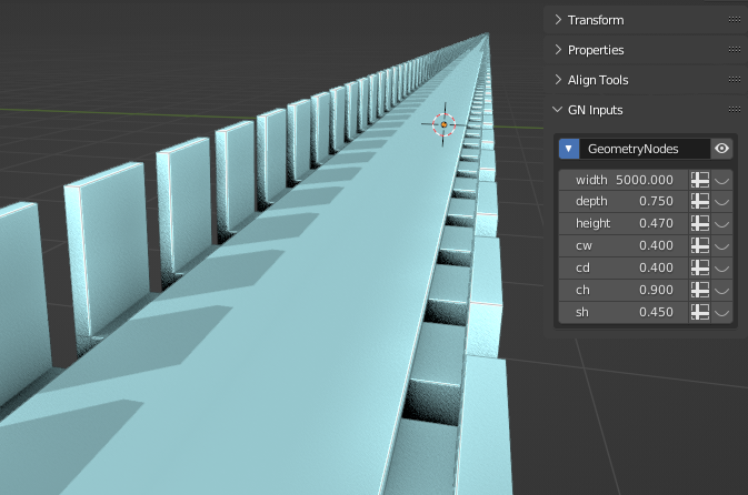
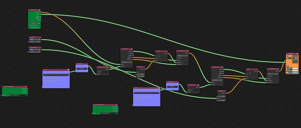
Hehe this inspired me to test it out in a GN tree.
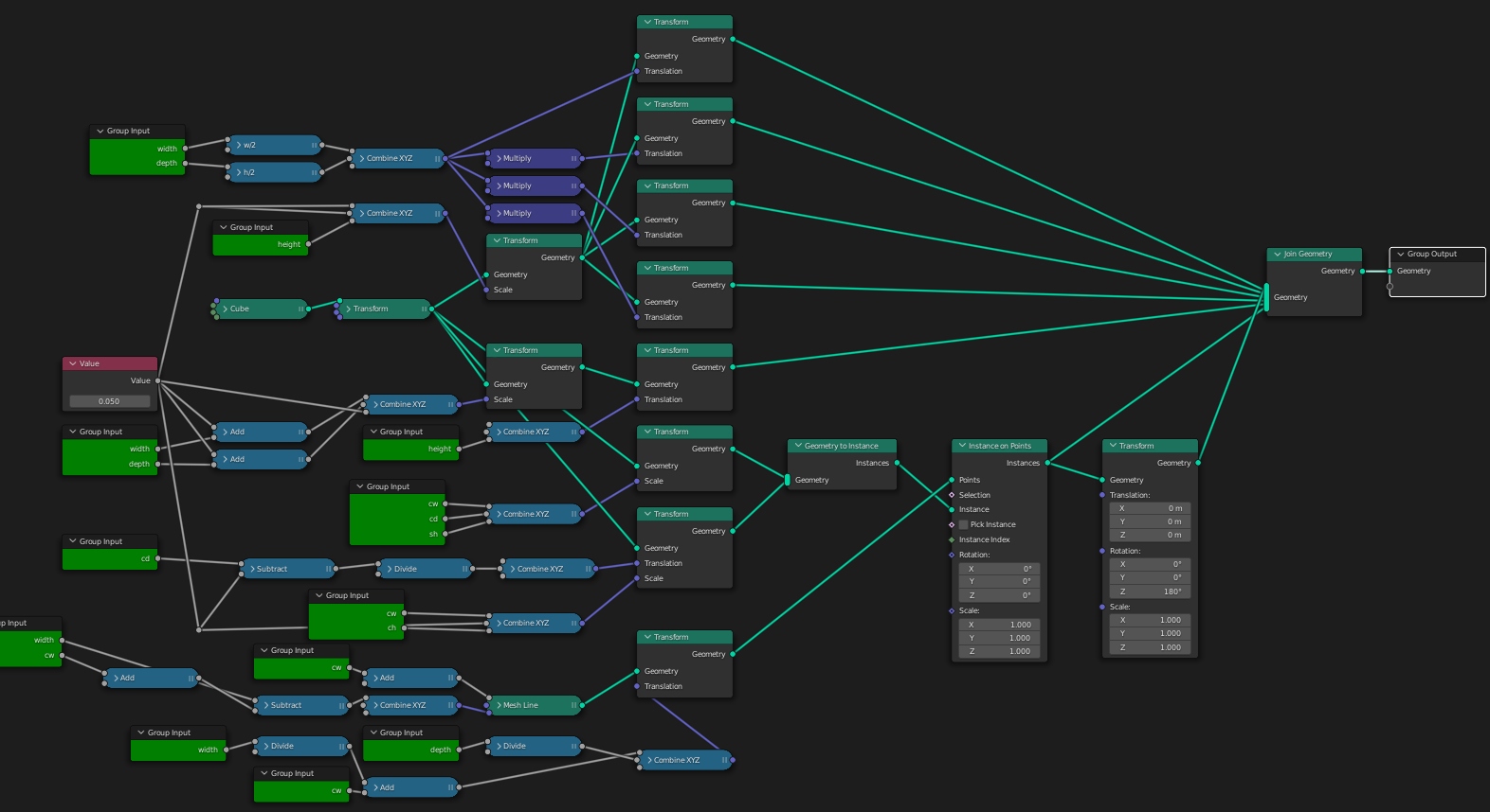
A lot of nodes but they're all simple maths operations. Until we have a dedicated equation node I'm afraid this is how it might look :)
I'll share the blend if anyone wants to play with it. Cheers
PS ideal if you're planning on receiving all your friends at once ><