@Moult
Without getting into details now, I believe it's straightforward to implement most points you listed above using geometry nodes. Conceptually if the layering geometry nodes keep the outline surfacesof the wall object that Blender BIM creates -as it currently does- and layers the "inside" of it, most the points above (2,3,4,5,8,9) are resolved - that is assuming BB already handles these cases correctly without the layers. Does BB currently handle these cases correctly as non-layered?
The key here is that geometry nodes start with the container geometry already produced by BB and modify that non-destucively.
Point 1 is adjusting for positive x and axis offset from origin to be possible with a query and adjustment of translations of the layered wall.
Point 6, seems the hardest and is not about just layering the container since priorities influence layers specifically.
Is there a document of variable names that BB uses.
Please help me how to query the data of walls from within Blender, i will use values of wall parameters as inputs to geometry nodes.
Thanks
@csimeon sure thing, you can indeed do an implementation with geometry nodes. You can query this data in IFC (there is no document of variable names since no data is actually stored in Blender properties, it's all in IFC). For example:
import blenderbim. tool as tool
element = tool.Ifc.get_entity(bpy.context.active_object)
material = ifcopenshell.util.element.get_material(element) # May be an IfcMaterialLayerSetUsage
layer_set = material.ForLayerSet
print(layer_set.TotalThickness)
print(layer_set.MaterialLayers)
Out of curiosity what are you trying to achieve with a geometry nodes implementation? The functionality almost already exists within IfcOpenShell already via APPLY_LAYERSETS (though ATPATH implementation is missing), and with a few tweaks to the existing viewport slicing which also already exists, we'll have it in vector drawings too.
Thanks for the query info. Layered walls was a good useful way for me to start my first exercises in Geometry Nodes, in a way that might be useful to me as an architect.
I thought the implementation does not exist... what do you mean
@Moult said:
The functionality almost already exists within IfcOpenShell already via APPLY_LAYERSETS (though ATPATH implementation is missing), and with a few tweaks to the existing viewport slicing which also already exists, we'll have it in vector drawings too.
I assume this can be found on a menu of the Blender BIM addon? where please?
Vector dxf / dwg ?
When we talk about layered walls there are a few aspects:
Defining the semantics of layered walls. This involves creating layers, layer sets, layer set usages, and rel connects relationships. This is fully implemented and already well covered in tutorials. It has been implemented for a couple years now, and rel connects implemented probably for a year.
Viewing layers in real time. This is also mostly implemented for most basic walls and you can see it in the animated GIF in the previous post. This was implemented recently and you can use it now via the daily builds, or wait until the stable release next week. There is no menu for this, just create a new drawing and you'll see it - it's always enabled.
Having vector drawings with CSS-stylable filled and merged sliced layers. This is not yet implemented, but probably will be soon (fingers crossed it'll be done in the next week, but if not, pretty soon after as it's just a small extension from number 2). There will probably be a drawing setting you can use to enable or disable this, as some drawings should show slices, whereas other drawings shouldn't.
Full 3D evaluation of the layers, sliced into 3D geometry. This is mostly implemented in IfcOpenShell but not exposed in the UI as it is missing a few things like ATPATH and there are some discrepancies with how axes are dealt with (see issue 1227). This feature has been around for perhaps a decade: https://blenderbim.org/docs-python/ifcopenshell/geometry_settings.html#apply-layersets
Vector drawings right now means vector SVG, which is semantically significantly richer than DXF/DWG. As mentioned in the other thread we also support automated conversion from SVG into DXF if using DXF is important for you.
Wow @csimeon that node looks impressive!! Out of curiosity, how is this done? C, Python? could you point to any resource on how to build custom geometry nodes?
It's a group node, which is a combination of Blender's native nodes, with a group input and output, that acts as one node with customized functionality, no coding language.
The Blender manual offers complete documentation, YouTube has numerous tutorials and usage examples.
Thanks, but not really, there are examples of using geometry nodes that do really amazing things, from parametric cities to abstract geometric constructs of great complexity.
@Moult said:
2. Viewing layers in real time. This is also mostly implemented for most basic walls and you can see it in the animated GIF in the previous post. This was implemented recently and you can use it now via the daily builds, or wait until the stable release next week. There is no menu for this, just create a new drawing and you'll see it - it's always enabled.
My BB version was pretty recent 23.03.04 and it did not have this (or I did not find it), so I downloaded today's build 23.05.01.
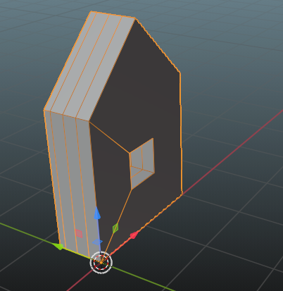
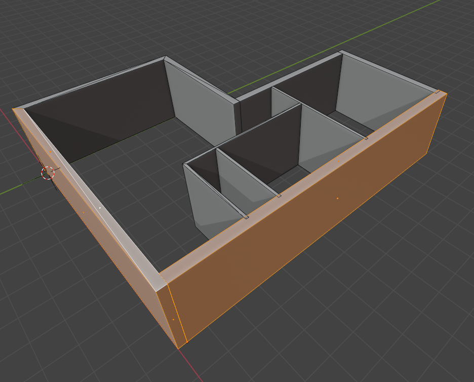
I have a basic Ifc file, just a few walls made a couple weeks ago with BB 23.03.04, some layered walls included. Not surprisingly loading the .blend file was the same, but loading the .ifc file lead to different 3D objects:
Walls (simple vertical) with the previous version were meshes, orthogonal parallelipeds with each of the 6 faces triangulated /2=12 faces. With today's BB version the representation of the same walls is with quads =6 faces, except for (some?! walls) for which the faces on the tops and on the bottoms of walls are triangulated =8 faces total! Shown above, on the left a simple wall constructed with 8faces (4 triangular at top and bottom), at right a layered wall, that only appears as a mesh with 6 faces.
The wall objects are identified as meshes in the outliner (Ifc hierarchy loaded) BUT trying to edit them returns a warning message "only mesh-compatible representations can be edited in edit mode". Strange message! a first in my experience with Blender of many years, so I figured the message is from BB that also is behind the edit restriction.
Unload BB and sure enough the object is a mesh.
@Moult No sign of layers in 3D mesh object. Are layers created with the cuts only? like the case in the gif you posted?
If indeed there are no layers in 3D, that for me is an important feature missing: as an architect owning a small scale business, BIM for me is a wish for an all purpose tool, including 3D modeling, 2D representations, Quantifying and Coordinating disciplines.
In 3D I want enough features there to start my renderings and image production. Layers are useful not only for quantifying but also to have the right materials setup to start texturing, on the road to producing rendered images.
That is why in my approach with the geometry nodes, I was was subdividing the thickness and adding the layer information in the 3D.
I'm sure you are way ahead of me in programming, after all I made a first effort only a couple days ago with the geometry nodes, but I do wonder if you intend to have wall layers in 3D or just in 2D representations?
What am I missing?
@csimeon there seem to be a few misunderstandings with your post. Firstly, I'd advise never to load a .blend file. The .blend file contains nothing but your session settings. All the data is in IFC. Treat the IFC as your native format, so save and load IFC. The "Import / Export" buttons are merely a remnant of the past and to aid discoverability for new users. Remember: you're now authoring an IFC database, not Blender anymore. Blender is just an interface.
Versions also change very, very quickly as this is still alpha software. So 23.03.04 (which is the last stable release) is actually extremely old and is missing hundreds of new features and fixes. You'll see this weekend when the next stable release is out of exactly how much has changed in 2 months in the release notes.
When IfcOpenShell loads geometry, it performs a tessellation function. This is because Blender is a mesh based software. However, the underlying representation in IFC may not be meshes. For walls, they are almost always not a mesh, instead, they are a solid extrusion. IFC has many geometry types, because in the AEC industry, there are many geometry types which are appropriate for different usecases. For the majority of simple AEC objects, meshes are not desirable, instead, solid extrusions are used (walls, slabs, columns, beams, etc). During the tessellation process, you may see extra triangles in Blender. These Blender mesh stats are meaningless. The underlying geometry is not a mesh. See the Object Properties > IFC Geometry panel to see what geometry types the wall has (unlike Blender, IFC objects may have multiple geometries).
A common problem with beginners is that they don't realise this difference and choose to edit non-mesh geometry as a Blender mesh. One of the recent changes is to block that to prevent incompatible solid geometries. There is always an option to cast a solid geometry into a mesh-like geometry (such as an IFC Tessellation or Faceted BRep), and then you can edit it as a mesh.
And yes, at the moment layers are only shown in cuts. The intention is to allow showing the layers in 3D too, and in theory with one line of code change you can already achieve it (see APPLY_LAYERSETS already mentioned above). But in my view this is not yet ready, so is not yet enabled. There is still some work to be done (ATPATH implementation, axis reconciliation) and this work needs to be done in C++ to be done properly (especially for multicore processing). Note that the visual absense of 3D layers has zero impact on quantification, all the semantic data is there. If this feature is critical for you, then maybe the BlenderBIM Add-on is not yet ready for you. The two best ways to accelerate this (apart from contributing to the C++ codebase of course) is to voice your support here https://github.com/IfcOpenShell/IfcOpenShell/issues/1227 and make a donation here https://opencollective.com/opensourcebim
Hope this helps explain! I hope you can tolerate the lack of maturity as alpha software, and continue to help testing and reporting bugs when you inevitably find them. It's a long road ahead, and end-to-end project delivery is one of the hardest usecases to achieve.
Most these points I understood already and thank you for laying them out in writing.
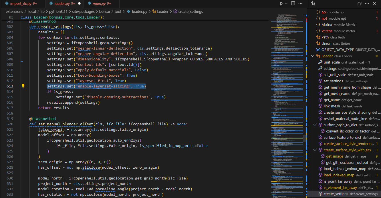
APPLY_LAYERSETS is the remaining question.... How please? I'll try typing at console...
... in blenderbim/bim/import_ifc.py underneath the existing line self.settings.set(self.settings.STRICT_TOLERANCE, True). Then, if you load an IFC with layered walls, they will be sliced.
@theoryshaw I am keen to see this work being done. I have read through the links provided and have the following questions...
Would this apply to floor and roof layers?
What is the thinking for representing non-solid layers like timber (lumber, wood) framing with insulation where graphically seeing correct centres and offsets?
Excited to see progress :)
Yes, any object that is defined with a IfcMaterialLayerSet. Theoretically, the representation (or geometry) of any object, from any IFC class, that uses IfcMaterialLayerSet, would apply.
What is the thinking for representing non-solid layers like timber (lumber, wood) framing with insulation where graphically seeing correct centres and offsets?
I would think similar to other BIM programs, that is, these types of 'layers' would be just abstracted as 'cubes'... that is, they would not be articulated with actual studs, or as repeating insulation cavities. I think that would be outside of scope. Even the main BIM authoring applications on the market don't provide this level of articulation of the various 'parts'.
Having vector drawings with CSS-stylable filled and merged sliced layers. This is not yet implemented, but probably will be soon (fingers crossed it'll be done in the next week, but if not, pretty soon after as it's just a small extension from number 2). There will probably be a drawing setting you can use to enable or disable this, as some drawings should show slices, whereas other drawings shouldn't.
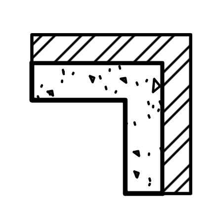
hi, is this already available? I'm trying to create a drawing showing multiple wall layers with individual hatches. Is ist possible with IfcMaterialLayerSet or do I have to use another way like IfcBuildingElementParts to create a drawing like this?
How is the 'coverings' tool supposed to work? Is there documentation anywhere?
I use it to create flooring, suspended ceilings
when you select the tool check the top menu, you can generate them automatically by simply positioning the 3D cursor inside the walls making a room
or you can use it in vertical layer to create plastering or generic cladding
let me know if the above is enough, cheers
Thanks, I tried for example to create a modified wall, re-assign it as an IfcCovering, SKIRTINGBOARD (named Skirt2), select the covering tool, look for that type - nothing there, so added new generic one (but the profile - how do I edit profiles?), but I guess I expected the 'covering' behaviour to glue-itself to the parent, which it doesn't - it's a free floating, separate element. So, maybe my broader question is how to create any profile? And can profiles exist in a project without being in the modelspace? (so they can be managed and drawn on when needed?).
Wow - that's a lot of steps. I might have to try it a few times as my homework tomorrow to remember! Blender crashed (OSX MBP M2) on the re-assign - the last step! I know how to rotate by r, axis (ie. 'x', 'y' or 'z') and typenumber, however I see you are rotation snapping to axes. I have rotation snap enabled but I am missing the hotkey you are using to get ortho snaps for rotate? What did I miss? Anyways - it's great to learn this piece - as it is a vital workflow for any kind of crown, base, or other coverings. However I was under the impression that this is also how one makes insulation fills, etc. Next up I will need to figure out how to group these items to walls! - If there is a grouping function - will extend extend all grouped items?
Also I hit 'recover last session' after my crash and got this:
Just wondering how to handle autosaves - and are they reliable? I am very used to stable ArchiCad backups (every 10 steps).
Wow - that's a lot of steps. I might have to try it a few times as my homework tomorrow to remember! Blender crashed (OSX MBP M2) on the re-assign - the last step! I know how to rotate by r, axis (ie. 'x', 'y' or 'z') and typenumber, however I see you are rotation snapping to axes. I have rotation snap enabled but I am missing the hotkey you are using to get ortho snaps for rotate? What did I miss?
Sorry I was in a hurry
no snapping needed, to rotate the IfcCovering[SKIRTINGBOARD] (extruded profile), after selecting it I used: R > X > 90 to take the skirting on the floor from its initial standing position R > Z > 90to turn the skirting counter-clockwise to rotate it along the wall
walls with infills is a tad more complex, (I think) you need to aggregate all into one entity , I haven't used this option for some time maybe someone would want to advise here ?
the creation of insulation panel itself is much easier, just use 'vertical layers' when creating your IfcCovering and assign it a thickness in Object Materials editor
A. create a profile matching the one of your board in Geometry and Materials > Profiles
B. click on the cube in the left hand side (T) menu, click on the waffle icon at the top to open the Type Manager
C. from the top drop-down menu in Type Manager choose 'IfcCoveringType', 1 Predefined Type: SKIRTINGBOARD, 2 Type Template: Extruded Profile, give it a name and 3 save it before 4 adding it to your model
If you only have one profile it automatically uses that one, otherwise you need to select the type and go to Geometry and Materials > Object Materials and edit the profile set and item (click on the pencils to edit and save it all on your way back)
Hi @steverugi you have done many great videos on quantity and cost extraction from Ifc in BBIM Bonsai. What should I watch first to start to learn this stuff? Has Bonsai menus changed a lot recently that would get me lost? Any pointers would gratefully accepted
Hi @Nigel
if you check this link there are videos (1 to 4 plus one on material resources) I made at the beginning of this year, there are some minor changes in the new version of Bonsai (apart from web output) but should be good enough to start
do you mind if I reverse your question: what would you like to learn first specifically? or main aspects related to quantities in Bonsai you would like to learn?
I can prepare something for you over the next weekend, who knows, step by step we could build up a mini series on Quantity Takeoff & Scheduling in Bonsai, maybe @iosvarms and @Massimo could join us or chip in if necessary
I think it's important to start from the user's need (like yours or others on this platform), hence my qestion ;)
@steverugi said:
Hi @Nigel
if you check this link there are videos (1 to 4 plus one on material resources) I made at the beginning of this year, there are some minor changes in the new version of Bonsai (apart from web output) but should be good enough to start
do you mind if I reverse your question: what would you like to learn first specifically? or main aspects related to quantities in Bonsai you would like to learn?
I can prepare something for you over the next weekend, who knows, step by step we could build up a mini series on Quantity Takeoff & Scheduling in Bonsai, maybe @iosvarms and @Massimo could join us or chip in if necessary
I think it's important to start from the user's need (like yours or others on this platform), hence my qestion ;)
... in blenderbim/bim/import_ifc.py underneath the existing line self.settings.set(self.settings.STRICT_TOLERANCE, True). Then, if you load an IFC with layered walls, they will be sliced.
Does this, or a different version of this work anymore?


Comments
@Moult
Without getting into details now, I believe it's straightforward to implement most points you listed above using geometry nodes. Conceptually if the layering geometry nodes keep the outline surfacesof the wall object that Blender BIM creates -as it currently does- and layers the "inside" of it, most the points above (2,3,4,5,8,9) are resolved - that is assuming BB already handles these cases correctly without the layers. Does BB currently handle these cases correctly as non-layered?
The key here is that geometry nodes start with the container geometry already produced by BB and modify that non-destucively.
Point 1 is adjusting for positive x and axis offset from origin to be possible with a query and adjustment of translations of the layered wall.
Point 6, seems the hardest and is not about just layering the container since priorities influence layers specifically.
Is there a document of variable names that BB uses.
Please help me how to query the data of walls from within Blender, i will use values of wall parameters as inputs to geometry nodes.
Thanks
@csimeon sure thing, you can indeed do an implementation with geometry nodes. You can query this data in IFC (there is no document of variable names since no data is actually stored in Blender properties, it's all in IFC). For example:
Out of curiosity what are you trying to achieve with a geometry nodes implementation? The functionality almost already exists within IfcOpenShell already via APPLY_LAYERSETS (though ATPATH implementation is missing), and with a few tweaks to the existing viewport slicing which also already exists, we'll have it in vector drawings too.
Thanks for the query info. Layered walls was a good useful way for me to start my first exercises in Geometry Nodes, in a way that might be useful to me as an architect.
I thought the implementation does not exist... what do you mean
I assume this can be found on a menu of the Blender BIM addon? where please?
Vector dxf / dwg ?
When we talk about layered walls there are a few aspects:
Vector drawings right now means vector SVG, which is semantically significantly richer than DXF/DWG. As mentioned in the other thread we also support automated conversion from SVG into DXF if using DXF is important for you.
Wow @csimeon that node looks impressive!! Out of curiosity, how is this done? C, Python? could you point to any resource on how to build custom geometry nodes?
It's a group node, which is a combination of Blender's native nodes, with a group input and output, that acts as one node with customized functionality, no coding language.
The Blender manual offers complete documentation, YouTube has numerous tutorials and usage examples.
Thanks, but not really, there are examples of using geometry nodes that do really amazing things, from parametric cities to abstract geometric constructs of great complexity.
My BB version was pretty recent 23.03.04 and it did not have this (or I did not find it), so I downloaded today's build 23.05.01.
I have a basic Ifc file, just a few walls made a couple weeks ago with BB 23.03.04, some layered walls included. Not surprisingly loading the .blend file was the same, but loading the .ifc file lead to different 3D objects:
If indeed there are no layers in 3D, that for me is an important feature missing: as an architect owning a small scale business, BIM for me is a wish for an all purpose tool, including 3D modeling, 2D representations, Quantifying and Coordinating disciplines.
In 3D I want enough features there to start my renderings and image production. Layers are useful not only for quantifying but also to have the right materials setup to start texturing, on the road to producing rendered images.
That is why in my approach with the geometry nodes, I was was subdividing the thickness and adding the layer information in the 3D.
I'm sure you are way ahead of me in programming, after all I made a first effort only a couple days ago with the geometry nodes, but I do wonder if you intend to have wall layers in 3D or just in 2D representations?
What am I missing?
@csimeon there seem to be a few misunderstandings with your post. Firstly, I'd advise never to load a .blend file. The .blend file contains nothing but your session settings. All the data is in IFC. Treat the IFC as your native format, so save and load IFC. The "Import / Export" buttons are merely a remnant of the past and to aid discoverability for new users. Remember: you're now authoring an IFC database, not Blender anymore. Blender is just an interface.
Versions also change very, very quickly as this is still alpha software. So 23.03.04 (which is the last stable release) is actually extremely old and is missing hundreds of new features and fixes. You'll see this weekend when the next stable release is out of exactly how much has changed in 2 months in the release notes.
When IfcOpenShell loads geometry, it performs a tessellation function. This is because Blender is a mesh based software. However, the underlying representation in IFC may not be meshes. For walls, they are almost always not a mesh, instead, they are a solid extrusion. IFC has many geometry types, because in the AEC industry, there are many geometry types which are appropriate for different usecases. For the majority of simple AEC objects, meshes are not desirable, instead, solid extrusions are used (walls, slabs, columns, beams, etc). During the tessellation process, you may see extra triangles in Blender. These Blender mesh stats are meaningless. The underlying geometry is not a mesh. See the Object Properties > IFC Geometry panel to see what geometry types the wall has (unlike Blender, IFC objects may have multiple geometries).
A common problem with beginners is that they don't realise this difference and choose to edit non-mesh geometry as a Blender mesh. One of the recent changes is to block that to prevent incompatible solid geometries. There is always an option to cast a solid geometry into a mesh-like geometry (such as an IFC Tessellation or Faceted BRep), and then you can edit it as a mesh.
And yes, at the moment layers are only shown in cuts. The intention is to allow showing the layers in 3D too, and in theory with one line of code change you can already achieve it (see APPLY_LAYERSETS already mentioned above). But in my view this is not yet ready, so is not yet enabled. There is still some work to be done (ATPATH implementation, axis reconciliation) and this work needs to be done in C++ to be done properly (especially for multicore processing). Note that the visual absense of 3D layers has zero impact on quantification, all the semantic data is there. If this feature is critical for you, then maybe the BlenderBIM Add-on is not yet ready for you. The two best ways to accelerate this (apart from contributing to the C++ codebase of course) is to voice your support here https://github.com/IfcOpenShell/IfcOpenShell/issues/1227 and make a donation here https://opencollective.com/opensourcebim
Hope this helps explain! I hope you can tolerate the lack of maturity as alpha software, and continue to help testing and reporting bugs when you inevitably find them. It's a long road ahead, and end-to-end project delivery is one of the hardest usecases to achieve.
Most these points I understood already and thank you for laying them out in writing.
APPLY_LAYERSETS is the remaining question.... How please? I'll try typing at console...
You can test APPLY_LAYERSETS by adding this line:
... in
blenderbim/bim/import_ifc.pyunderneath the existing lineself.settings.set(self.settings.STRICT_TOLERANCE, True). Then, if you load an IFC with layered walls, they will be sliced.If anyone wants to help fund the development of visualizing layers in BlenderBIM.
https://opencollective.com/osarch/projects/visualize_layers_in_blenderbim
@theoryshaw I am keen to see this work being done. I have read through the links provided and have the following questions...
Would this apply to floor and roof layers?
What is the thinking for representing non-solid layers like timber (lumber, wood) framing with insulation where graphically seeing correct centres and offsets?
Excited to see progress :)
Yes, any object that is defined with a IfcMaterialLayerSet. Theoretically, the representation (or geometry) of any object, from any IFC class, that uses IfcMaterialLayerSet, would apply.
I would think similar to other BIM programs, that is, these types of 'layers' would be just abstracted as 'cubes'... that is, they would not be articulated with actual studs, or as repeating insulation cavities. I think that would be outside of scope. Even the main BIM authoring applications on the market don't provide this level of articulation of the various 'parts'.
hi, is this already available? I'm trying to create a drawing showing multiple wall layers with individual hatches. Is ist possible with IfcMaterialLayerSet or do I have to use another way like IfcBuildingElementParts to create a drawing like this?
From my understanding, this is not implemented yet.
How is the 'coverings' tool supposed to work? Is there documentation anywhere?
hi @Andyro
I use it to create flooring, suspended ceilings
when you select the tool check the top menu, you can generate them automatically by simply positioning the 3D cursor inside the walls making a room
or you can use it in vertical layer to create plastering or generic cladding
let me know if the above is enough, cheers
Thanks, I tried for example to create a modified wall, re-assign it as an IfcCovering, SKIRTINGBOARD (named Skirt2), select the covering tool, look for that type - nothing there, so added new generic one (but the profile - how do I edit profiles?), but I guess I expected the 'covering' behaviour to glue-itself to the parent, which it doesn't - it's a free floating, separate element. So, maybe my broader question is how to create any profile? And can profiles exist in a project without being in the modelspace? (so they can be managed and drawn on when needed?).
Hi @Andyro
please see video attached if could be useful
Wow - that's a lot of steps. I might have to try it a few times as my homework tomorrow to remember! Blender crashed (OSX MBP M2) on the re-assign - the last step! I know how to rotate by r, axis (ie. 'x', 'y' or 'z') and typenumber, however I see you are rotation snapping to axes. I have rotation snap enabled but I am missing the hotkey you are using to get ortho snaps for rotate? What did I miss? Anyways - it's great to learn this piece - as it is a vital workflow for any kind of crown, base, or other coverings. However I was under the impression that this is also how one makes insulation fills, etc. Next up I will need to figure out how to group these items to walls! - If there is a grouping function - will extend extend all grouped items?
Also I hit 'recover last session' after my crash and got this:
Just wondering how to handle autosaves - and are they reliable? I am very used to stable ArchiCad backups (every 10 steps).
Hi @Andyro
Sorry I was in a hurry
no snapping needed, to rotate the IfcCovering[SKIRTINGBOARD] (extruded profile), after selecting it I used:
R>X>90to take the skirting on the floor from its initial standing positionR>Z>90to turn the skirting counter-clockwise to rotate it along the wallwalls with infills is a tad more complex, (I think) you need to aggregate all into one entity , I haven't used this option for some time maybe someone would want to advise here ?
the creation of insulation panel itself is much easier, just use 'vertical layers' when creating your IfcCovering and assign it a thickness in Object Materials editor
hope it helps
main steps to create a skirting board
A. create a profile matching the one of your board in Geometry and Materials > Profiles
B. click on the cube in the left hand side (T) menu, click on the waffle icon at the top to open the Type Manager
C. from the top drop-down menu in Type Manager choose 'IfcCoveringType', 1 Predefined Type: SKIRTINGBOARD, 2 Type Template: Extruded Profile, give it a name and 3 save it before 4 adding it to your model
If you only have one profile it automatically uses that one, otherwise you need to select the type and go to Geometry and Materials > Object Materials and edit the profile set and item (click on the pencils to edit and save it all on your way back)
to rotate it can use the steps above
enjoy ;)
Hi @steverugi you have done many great videos on quantity and cost extraction from Ifc in BBIM Bonsai. What should I watch first to start to learn this stuff? Has Bonsai menus changed a lot recently that would get me lost? Any pointers would gratefully accepted
Hi @Nigel
if you check this link there are videos (1 to 4 plus one on material resources) I made at the beginning of this year, there are some minor changes in the new version of Bonsai (apart from web output) but should be good enough to start
do you mind if I reverse your question: what would you like to learn first specifically? or main aspects related to quantities in Bonsai you would like to learn?
I can prepare something for you over the next weekend, who knows, step by step we could build up a mini series on Quantity Takeoff & Scheduling in Bonsai, maybe @iosvarms and @Massimo could join us or chip in if necessary
I think it's important to start from the user's need (like yours or others on this platform), hence my qestion ;)
cheers
I'm overwhelmed, thank you so much
Does this, or a different version of this work anymore?
I tried that, but it crashed Blender...