@yorik I think BlenderBIM schould be able to have more options: 1. import as close to the Ifc definition as possible (beam defined as an axis with profile as beveled curve, extruded wall as mesh face with modifier and so on) 2. all mesh 3. some other we agree on?
I hope we get the workflow from topologic soon and will be able to ditch the "2d->extrude->..." workflow and work with spaces only. But until we do, my ideal would be something like this:
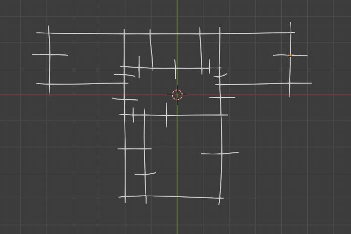
1. sketch, similar to what @DADA_universe did here https://community.osarch.org/discussion/comment/1782#Comment_1782 (I imported my sketch from inkscape)
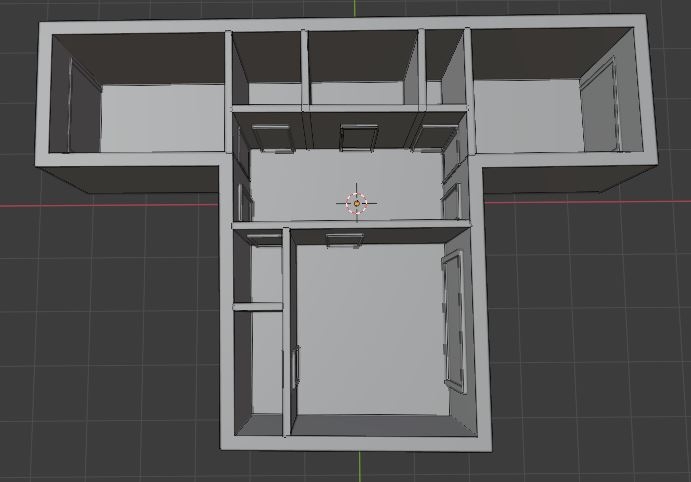
2. generate walls and openings by digitizing the sketch (simply add vertexes on intersections, unless the intersection is close to the stroke center, in that case opening, or something like that, I just redraw the sketch manually and added modifiers)
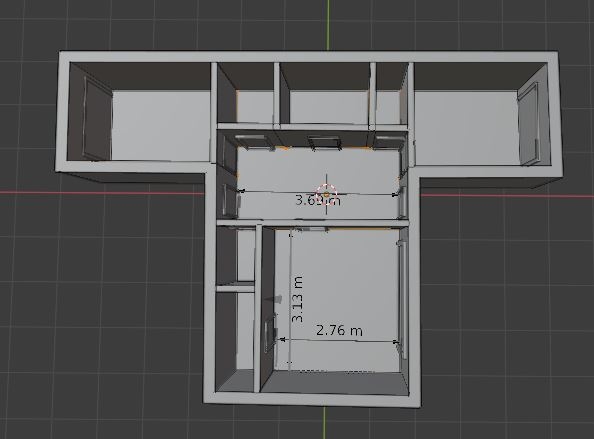
3. fix some points and add dimension constraints, refine the model by overwriting the dimensions and so on (right now I don't know about anything in blender able to do this?)
Generally start from a sketch of spaces and refine, this could work as a base for the topologic workflow as well.
That would be very interesting to have. However, you're generating doors and windows as objects with fixed width. It would be nicer if we could define the width of doors and windows on the sketch too, using some means of identifying where they start and end.
There are a lot of examples of doors/windows that are tangent to walls and that possibility may also be difficult to detect by the software.
Some kind of symbols for openings could probably be used to clearly mark openings.
Maybe there can be a way that connects points to a grid (like a structural grid) and forces walls to be generated orthogonally to the grid. Architecture is a fluid that boils at 90o most of the time.
Having sketches turn into Bézier splines or other type of regular curves would also be cool. I don't know if it's even remotely possible.
@JanF said: @yorik I think BlenderBIM schould be able to have more options: 1. import as close to the Ifc definition as possible (beam defined as an axis with profile as beveled curve, extruded wall as mesh face with modifier and so on) 2. all mesh 3. some other we agree on?
I hope we get the workflow from topologic soon and will be able to ditch the "2d->extrude->..." workflow and work with spaces only. But until we do, my ideal would be something like this:
1. sketch, similar to what @DADA_universe did here https://community.osarch.org/discussion/comment/1782#Comment_1782 (I imported my sketch from inkscape)
2. generate walls and openings by digitizing the sketch (simply add vertexes on intersections, unless the intersection is close to the stroke center, in that case opening, or something like that, I just redraw the sketch manually and added modifiers)
3. fix some points and add dimension constraints, refine the model by overwriting the dimensions and so on (right now I don't know about anything in blender able to do this?)
Generally start from a sketch of spaces and refine, this could work as a base for the topologic workflow as well.
@JanF I find your thoughts on this and @JQL 's addition to it quite interesting and it all got me thinking. Caveat though, what I'm about to touch on is just a thought experiment and not something I may be able to implement, I'm however wondering if anyone can make sense of it in some way.
If we look at those line sketches as a graphical representation of a 'language' for architecture, i.e. orthography of sorts, with the symbols and how they are arranged having meaning, can we take it one step further and make that language programmable, such that different symbol combinations can be used to generate volumes and the meshes enclosing those volumes according to pre-defined rules? I have not said anything new here, I have only re-presented what has others have said before.
Regarding volumes, there is the concept of colliders in game development which helps in defining volumes and detecting when they are crossed. I've always thought that the way colliders are used could probably be adapted for the sort of problems Topologic tries to solve in terms of articulation of volumes and not just meshes in architectural representation. This made me think of the Godot Game Engine and the fact that it has already been used to build very powerful painting apps, so its ability to build sketch tools is proven. I asked on the Godot Page on Facebook and got two recommendations for libraries that potentially could be integrated with Godot for some form of pattern recognition for line sketches / symbols:
1) https://depts.washington.edu/acelab/proj/dollar/pdollar.html
2) https://tcbmi.com/strokeit/
The first one in particular seems plausible, there is a demo that works on the page. It has Python versions (amongst others) available and is distributed under the New BSD License. Perhaps it can be integrated into Blender? I don't know how the collider concept would be integrated in Blender though.......such a concept existed in the Blender Game Engine but has now been removed unfortunately.
My pitch is that if we had a way of sketching / doodling (with a mouse or digital pen) and a system (or grammar) for representing doors, walls, windows (it should also be possible to sketch in 3d) etc with simple symbols (like the suggestion by @JQL for indicating doors) and a symbol for creating volumes, naming them and defining their relationship to walls, doors, windows (I understand from @topologic's previous interventions that the volumes probably should be defined first, and that makes absolute sense), and then a magic button you can press which calls up a pop up that asks you to either change parameters for stuff like window heights, wall thicknesses, etc, or accept default values, after which the doodle is used to generate Blender (Archipack?) objects based on those parameters, with the relationship with the volumes / colliders still being maintained. BlenderBIM can then chew this material and make more magic out of it. It really would be a beautiful thing.......I think.
My suggestion would still be to do this with Blender Grease pencil objects, and this recent ability to trace bitmaps into Grease Pencil objects means that you can ''code'' your doodle by sketching the old fashioned way on paper, using the appropriate symbols and then scan and import into Blender, and when you trace the image into Grease Pencil, you would then be able to press the magic button to generate a 3d model from your sketch. I've obviously over simplified a fairly complex set up with my pseudo code, but I imagine this should be possible and it could be a workflow that would catch on for fast iteration for early stage design and concept development in Blender.
Here's a bonus link to an article / tutorial on using Grease Pencil for generative art for some more Grease Pencil inspiration.
Hi everyone! This might be a good place to show a certain concept sketch i made for architectural element creation / editing for Blender, done a couple years ago. I just revisited it and it seems it still has some value to it. Stephen might recognize it, i think i showed it to him at some point of his Archipack development evolution.
It deals with basic wall / opening creation and editing, the way i think most of us architects would like to have in real architectural production environment. It exists in three layers - a simple vector sketch for user to edit, an autogenerated base plan for 2D representation and an autogenerated 3D geometry for everything else. In this case, the user manipulates the first, sketch layer exclusively.
I think it would be good idea to think a little bit about these basic, high level pipeline concepts that would be visible and quickly - understandable to a broader AEC / archvis community and give some energy to ever-lasting primitive tool and snapping issues in core Blender.
@JanF said: @yorik I think BlenderBIM schould be able to have more options: 1. import as close to the Ifc definition as possible (beam defined as an axis with profile as beveled curve, extruded wall as mesh face with modifier and so on) 2. all mesh 3. some other we agree on?
I hope we get the workflow from topologic soon and will be able to ditch the "2d->extrude->..." workflow and work with spaces only. But until we do, my ideal would be something like this:
1. sketch, similar to what @DADA_universe did here https://community.osarch.org/discussion/comment/1782#Comment_1782 (I imported my sketch from inkscape)
2. generate walls and openings by digitizing the sketch (simply add vertexes on intersections, unless the intersection is close to the stroke center, in that case opening, or something like that, I just redraw the sketch manually and added modifiers)
3. fix some points and add dimension constraints, refine the model by overwriting the dimensions and so on (right now I don't know about anything in blender able to do this?)
Generally start from a sketch of spaces and refine, this could work as a base for the topologic workflow as well.
@JanF I find your thoughts on this and @JQL 's addition to it quite interesting and it all got me thinking. Caveat though, what I'm about to touch on is just a thought experiment and not something I may be able to implement, I'm however wondering if anyone can make sense of it in some way.
If we look at those line sketches as a graphical representation of a 'language' for architecture, i.e. orthography of sorts, with the symbols and how they are arranged having meaning, can we take it one step further and make that language programmable, such that different symbol combinations can be used to generate volumes and the meshes enclosing those volumes according to pre-defined rules? I have not said anything new here, I have only re-presented what has others have said before.
Regarding volumes, there is the concept of colliders in game development which helps in defining volumes and detecting when they are crossed. I've always thought that the way colliders are used could probably be adapted for the sort of problems Topologic tries to solve in terms of articulation of volumes and not just meshes in architectural representation. This made me think of the Godot Game Engine and the fact that it has already been used to build very powerful painting apps, so its ability to build sketch tools is proven. I asked on the Godot Page on Facebook and got two recommendations for libraries that potentially could be integrated with Godot for some form of pattern recognition for line sketches / symbols:
1) https://depts.washington.edu/acelab/proj/dollar/pdollar.html
2) https://tcbmi.com/strokeit/
The first one in particular seems plausible, there is a demo that works on the page. It has Python versions (amongst others) available and is distributed under the New BSD License. Perhaps it can be integrated into Blender? I don't know how the collider concept would be integrated in Blender though.......such a concept existed in the Blender Game Engine but has now been removed unfortunately.
My pitch is that if we had a way of sketching / doodling (with a mouse or digital pen) and a system (or grammar) for representing doors, walls, windows (it should also be possible to sketch in 3d) etc with simple symbols (like the suggestion by @JQL for indicating doors) and a symbol for creating volumes, naming them and defining their relationship to walls, doors, windows (I understand from @topologic's previous interventions that the volumes probably should be defined first, and that makes absolute sense), and then a magic button you can press which calls up a pop up that asks you to either change parameters for stuff like window heights, wall thicknesses, etc, or accept default values, after which the doodle is used to generate Blender (Archipack?) objects based on those parameters, with the relationship with the volumes / colliders still being maintained. BlenderBIM can then chew this material and make more magic out of it. It really would be a beautiful thing.......I think.
My suggestion would still be to do this with Blender Grease pencil objects, and this recent ability to trace bitmaps into Grease Pencil objects means that you can ''code'' your doodle by sketching the old fashioned way on paper, using the appropriate symbols and then scan and import into Blender, and when you trace the image into Grease Pencil, you would then be able to press the magic button to generate a 3d model from your sketch. I've obviously over simplified a fairly complex set up with my pseudo code, but I imagine this should be possible and it could be a workflow that would catch on for fast iteration for early stage design and concept development in Blender.
Here's a bonus link to an article / tutorial on using Grease Pencil for generative art for some more Grease Pencil inspiration.
Quick update that @brunopostle has created an intriguing tool called Topologise, which builds on his Homemaker suite of tools and approximates a good part of what I rambled about here, right inside Blender (see this thread and this video and this video). It's the grammar / shorthand system for sketching symbols that can be recognized for doors, windows and other elements that is now missing really. (Still hoping to see how Topologise will handle the distinction between volumes and spaces as distinct from the building elements that connect / separate them, but that conversation was central to the Topologic thread anyway) Once that can be created and parsed successfully within Blender, from Grease Pencil objects, it would then be possible to use free hand sketching in Blender to create Grease Pencil object with the recognizable grammar, convert this into a mesh of cells that Topologise can chew and take the result into either Archipack and / or BlenderBIM for further processing. Fascinating to think of this possibility.
What also should be thought is how the innacuracy of a sketch can be translated to an accurate model. I suppose the generated spaces or walls should be easily fine-tunes in both dimensions, linear/curvilinear shapes, and angles.
@Okavango, I made a gif of the image sequence you shared to make it easier to see what you're referring to here. I see a way of combining the context menu approach you're suggesting with what @JanF has demonstrated above using Grease Pencil strokes and Sverchok to generate walls, to achieve a simpler implementation of what I've been rambling about. Let's say it's an addon called ArchiSketch (doesn't have to be a standalone addon, can be part of a suit of tools), you have a button which activates ArchiSketch while in Draw mode with GreasePencil (much like how Stephen implemented the CAD transform tools. This reveals the three buttons you have represented here- Walls, Openings and Edit. When you have walls selected, the Grease Pencil lines will be interpreted as walls as illustrated in JanF's gif above. If you have ''Openings'' selected however, drawing two parallel lines across a wall line would create an opening at the space defined between the two parallel lines. The properties of the opening can then be tweaked with the ''Edit'' context menu, to assign either a door or a window to the opening, or to just leave it as a clear opening. Other parameters like dimensions, etc can also be tweaked. All this is what your proposal already suggests and I think it makes a lot of sense.
Some months ago, I shared some ideas with Dion and Stephen to build a custom interface for BlenderBIM and use asset manager, and some obstacles there ware about snapping in Blender, and also Booleans
So, Dion didn't follow the idea, but thanks Stephen @stephen_l and @Andyrexic who did some invaluable improvements
Also, I like your @JanF demo
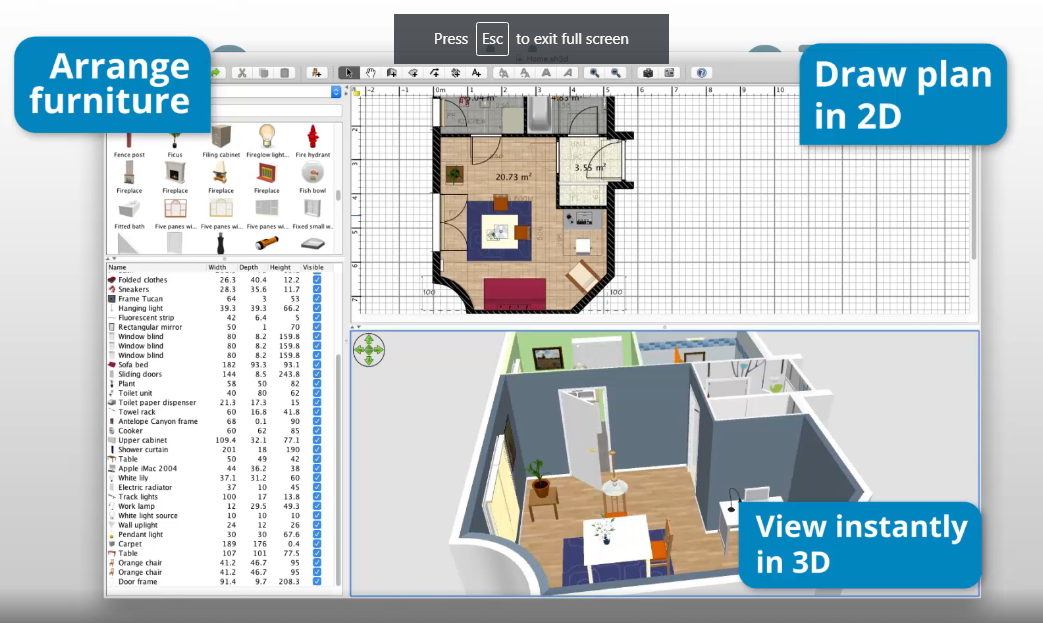
I think Sweet Home 3D follows a logical UX/UI approach, and we can build something even better on Blender
@ReD_CoDE said:
I think Sweet Home 3D follows a logical UX/UI approach, and we can build something even better on Blender
Yes having Andrew commit to creating an AEC application template coupled with his Asset management solutions will give a big boost. Great opportunity to have improved UI / workflows for AEC work in Blender.
However, Dion @Moult had two great choices, the first one was choosing Blender and IfcOpenShell's Blender plugin to develop, the second one is Inkscape
@JanF I think it should have a setting for placing walls, like choosing "wall reference line"
Also, it can be used in other areas too, for instance, for defining axes, etc
@ReD_CoDE said: @JanF I think it should have a setting for placing walls, like choosing "wall reference line"
Also, it can be used in other areas too, for instance, for defining axes, etc
It's basically only a demonstration of what I meant. I'm doing this to develop the principal idea and to see if anyone is interested in this. I'm still missing one final basic step I described previously - dimensioning the resulting objects and finetuning their positions by rewriting the dimension values and right now I have no idea how to go about that.
@theoryshaw said: @JanF your simple wall demo with the grease pencil got a good response in the Twitterverse.
Well done!
Hahah, cool. I added a layer for doors and windows, deciding by stroke length:
This is so cool. And my mind, as an architect, is blowing out. Since the new way of sketching can be found right here.
Since i know very little about programming and python, i wonder. Does it decide door or window by stroke length? Can introducing color make it easier to define what is drawn. Chosing red is a window 55x120 , blue is a door etc..
Might be stupid might not be. Anyhow this is so exciting..
Since i know very little about programming and python, i wonder. Does it decide door or window by stroke length? Can introducing color make it easier to define what is drawn. Chosing red is a window 55x120 , blue is a door etc..
Might be stupid might not be. Anyhow this is so exciting..
Cheers
Yes, right now I made it decide by stroke length, for two reasons. First, it's faster. Switching colours/layers/etc. takes clicks, different stroke lengths are much more fluent. Second, I personally draw like this - first sketch everything with one colour and then eventually highlight important stuff/add details with other colours.
My goal is to test out a fluent workflow (right now I do the sketch and then draw the same thing over in cad when I'm happy with the design) I hope I could sketch, get a simple model, refine, correct the sketch if something doesn't work, but keep the detail I already added.
Apart from the increased efficiency I also hope that this way would keep the sketches present throughout the design process and therefore better preserve the design intention.
How would you go about defining the height of the opening? Also, in this version you would have to have parametric windows to make use of the width information, which is why I added only openings now.


Comments
@yorik I think BlenderBIM schould be able to have more options: 1. import as close to the Ifc definition as possible (beam defined as an axis with profile as beveled curve, extruded wall as mesh face with modifier and so on) 2. all mesh 3. some other we agree on?
I hope we get the workflow from topologic soon and will be able to ditch the "2d->extrude->..." workflow and work with spaces only. But until we do, my ideal would be something like this:
1. sketch, similar to what @DADA_universe did here https://community.osarch.org/discussion/comment/1782#Comment_1782 (I imported my sketch from inkscape)
2. generate walls and openings by digitizing the sketch (simply add vertexes on intersections, unless the intersection is close to the stroke center, in that case opening, or something like that, I just redraw the sketch manually and added modifiers)
3. fix some points and add dimension constraints, refine the model by overwriting the dimensions and so on (right now I don't know about anything in blender able to do this?)
Generally start from a sketch of spaces and refine, this could work as a base for the topologic workflow as well.
That would be very interesting to have. However, you're generating doors and windows as objects with fixed width. It would be nicer if we could define the width of doors and windows on the sketch too, using some means of identifying where they start and end.
There are a lot of examples of doors/windows that are tangent to walls and that possibility may also be difficult to detect by the software.
Some kind of symbols for openings could probably be used to clearly mark openings.
There is an example o Github's sverchok page similar to this by enzime69:
The link to sverchok page where it's featured:
https://github.com/nortikin/sverchok/issues/2814
Maybe it would be interesting to talk with enzime69 as he's probably doing something similar to what @DADA_universe did, but with sverchok
I'm still miles away from this. I'm just figuring out blender.
My idea was to use the length of the perpendicular stroke to roughly estimate the planned width of the opening ?
Maybe there can be a way that connects points to a grid (like a structural grid) and forces walls to be generated orthogonally to the grid. Architecture is a fluid that boils at 90o most of the time.
Having sketches turn into Bézier splines or other type of regular curves would also be cool. I don't know if it's even remotely possible.
@JanF I find your thoughts on this and @JQL 's addition to it quite interesting and it all got me thinking. Caveat though, what I'm about to touch on is just a thought experiment and not something I may be able to implement, I'm however wondering if anyone can make sense of it in some way.
If we look at those line sketches as a graphical representation of a 'language' for architecture, i.e. orthography of sorts, with the symbols and how they are arranged having meaning, can we take it one step further and make that language programmable, such that different symbol combinations can be used to generate volumes and the meshes enclosing those volumes according to pre-defined rules? I have not said anything new here, I have only re-presented what has others have said before.
Regarding volumes, there is the concept of colliders in game development which helps in defining volumes and detecting when they are crossed. I've always thought that the way colliders are used could probably be adapted for the sort of problems Topologic tries to solve in terms of articulation of volumes and not just meshes in architectural representation. This made me think of the Godot Game Engine and the fact that it has already been used to build very powerful painting apps, so its ability to build sketch tools is proven. I asked on the Godot Page on Facebook and got two recommendations for libraries that potentially could be integrated with Godot for some form of pattern recognition for line sketches / symbols:
1) https://depts.washington.edu/acelab/proj/dollar/pdollar.html
2) https://tcbmi.com/strokeit/
The first one in particular seems plausible, there is a demo that works on the page. It has Python versions (amongst others) available and is distributed under the New BSD License. Perhaps it can be integrated into Blender? I don't know how the collider concept would be integrated in Blender though.......such a concept existed in the Blender Game Engine but has now been removed unfortunately.
My pitch is that if we had a way of sketching / doodling (with a mouse or digital pen) and a system (or grammar) for representing doors, walls, windows (it should also be possible to sketch in 3d) etc with simple symbols (like the suggestion by @JQL for indicating doors) and a symbol for creating volumes, naming them and defining their relationship to walls, doors, windows (I understand from @topologic's previous interventions that the volumes probably should be defined first, and that makes absolute sense), and then a magic button you can press which calls up a pop up that asks you to either change parameters for stuff like window heights, wall thicknesses, etc, or accept default values, after which the doodle is used to generate Blender (Archipack?) objects based on those parameters, with the relationship with the volumes / colliders still being maintained. BlenderBIM can then chew this material and make more magic out of it. It really would be a beautiful thing.......I think.
My suggestion would still be to do this with Blender Grease pencil objects, and this recent ability to trace bitmaps into Grease Pencil objects means that you can ''code'' your doodle by sketching the old fashioned way on paper, using the appropriate symbols and then scan and import into Blender, and when you trace the image into Grease Pencil, you would then be able to press the magic button to generate a 3d model from your sketch. I've obviously over simplified a fairly complex set up with my pseudo code, but I imagine this should be possible and it could be a workflow that would catch on for fast iteration for early stage design and concept development in Blender.
Here's a bonus link to an article / tutorial on using Grease Pencil for generative art for some more Grease Pencil inspiration.
As far as i'm aware, Potrace only create lines between areas of different colors, but is not able to actually trace from lines.
I don't know for sure.
Hi everyone! This might be a good place to show a certain concept sketch i made for architectural element creation / editing for Blender, done a couple years ago. I just revisited it and it seems it still has some value to it. Stephen might recognize it, i think i showed it to him at some point of his Archipack development evolution.
It deals with basic wall / opening creation and editing, the way i think most of us architects would like to have in real architectural production environment. It exists in three layers - a simple vector sketch for user to edit, an autogenerated base plan for 2D representation and an autogenerated 3D geometry for everything else. In this case, the user manipulates the first, sketch layer exclusively.
I think it would be good idea to think a little bit about these basic, high level pipeline concepts that would be visible and quickly - understandable to a broader AEC / archvis community and give some energy to ever-lasting primitive tool and snapping issues in core Blender.
Quick update that @brunopostle has created an intriguing tool called Topologise, which builds on his Homemaker suite of tools and approximates a good part of what I rambled about here, right inside Blender (see this thread and this video and this video). It's the grammar / shorthand system for sketching symbols that can be recognized for doors, windows and other elements that is now missing really. (Still hoping to see how Topologise will handle the distinction between volumes and spaces as distinct from the building elements that connect / separate them, but that conversation was central to the Topologic thread anyway) Once that can be created and parsed successfully within Blender, from Grease Pencil objects, it would then be possible to use free hand sketching in Blender to create Grease Pencil object with the recognizable grammar, convert this into a mesh of cells that Topologise can chew and take the result into either Archipack and / or BlenderBIM for further processing. Fascinating to think of this possibility.
What also should be thought is how the innacuracy of a sketch can be translated to an accurate model. I suppose the generated spaces or walls should be easily fine-tunes in both dimensions, linear/curvilinear shapes, and angles.
I tried to build a simple demo for sketch walls using grease pencil and sverchok, I think it could be a fun way to work.
@Okavango, I made a gif of the image sequence you shared to make it easier to see what you're referring to here. I see a way of combining the context menu approach you're suggesting with what @JanF has demonstrated above using Grease Pencil strokes and Sverchok to generate walls, to achieve a simpler implementation of what I've been rambling about. Let's say it's an addon called ArchiSketch (doesn't have to be a standalone addon, can be part of a suit of tools), you have a button which activates ArchiSketch while in Draw mode with GreasePencil (much like how Stephen implemented the CAD transform tools. This reveals the three buttons you have represented here- Walls, Openings and Edit. When you have walls selected, the Grease Pencil lines will be interpreted as walls as illustrated in JanF's gif above. If you have ''Openings'' selected however, drawing two parallel lines across a wall line would create an opening at the space defined between the two parallel lines. The properties of the opening can then be tweaked with the ''Edit'' context menu, to assign either a door or a window to the opening, or to just leave it as a clear opening. Other parameters like dimensions, etc can also be tweaked. All this is what your proposal already suggests and I think it makes a lot of sense.
Some months ago, I shared some ideas with Dion and Stephen to build a custom interface for BlenderBIM and use asset manager, and some obstacles there ware about snapping in Blender, and also Booleans
So, Dion didn't follow the idea, but thanks Stephen @stephen_l and @Andyrexic who did some invaluable improvements
Also, I like your @JanF demo
I think Sweet Home 3D follows a logical UX/UI approach, and we can build something even better on Blender
Yes having Andrew commit to creating an AEC application template coupled with his Asset management solutions will give a big boost. Great opportunity to have improved UI / workflows for AEC work in Blender.
However, Dion @Moult had two great choices, the first one was choosing Blender and IfcOpenShell's Blender plugin to develop, the second one is Inkscape
@JanF I think it should have a setting for placing walls, like choosing "wall reference line"
Also, it can be used in other areas too, for instance, for defining axes, etc
@JanF your simple wall demo with the grease pencil got a good response in the Twitterverse.
Well done!
Looks great! Thanks for the help!
Hahah, cool. I added a layer for doors and windows, deciding by stroke length:
It's basically only a demonstration of what I meant. I'm doing this to develop the principal idea and to see if anyone is interested in this. I'm still missing one final basic step I described previously - dimensioning the resulting objects and finetuning their positions by rewriting the dimension values and right now I have no idea how to go about that.
I'm definitely interested in this. It's very promising and the dimensions idea is great.
@JanF I've waited to see what're IFC nodes Dion @Moult develops with the Sverchok team. Then it'd be much cleary what we need to do all together
This is so cool. And my mind, as an architect, is blowing out. Since the new way of sketching can be found right here.
Since i know very little about programming and python, i wonder. Does it decide door or window by stroke length? Can introducing color make it easier to define what is drawn. Chosing red is a window 55x120 , blue is a door etc..
Might be stupid might not be. Anyhow this is so exciting..
Cheers
Yes, right now I made it decide by stroke length, for two reasons. First, it's faster. Switching colours/layers/etc. takes clicks, different stroke lengths are much more fluent. Second, I personally draw like this - first sketch everything with one colour and then eventually highlight important stuff/add details with other colours.
My goal is to test out a fluent workflow (right now I do the sketch and then draw the same thing over in cad when I'm happy with the design) I hope I could sketch, get a simple model, refine, correct the sketch if something doesn't work, but keep the detail I already added.
Apart from the increased efficiency I also hope that this way would keep the sketches present throughout the design process and therefore better preserve the design intention.
Do you think it would be very hard to make two ticks in the wall to define window width?
In the simplest form it's not hard:
How would you go about defining the height of the opening? Also, in this version you would have to have parametric windows to make use of the width information, which is why I added only openings now.
This is really great stuff! How easy is it to convert Sverchok scripts into Python code that can be run as an add-on?
That is absolutely great!