I've recently played with freecad sketches for Architecture concepts and was much impressed with how easy it was to create geometric constrains with it and I saw great potential on FreeCAD because of them.
However, I noticed that if I generated building's geometry from the sketches and at a later time added other geometry to the base sketches the whole building model went all over the place. I finally gave up and got back to using Sketchup. However, if that is ever fixed, FreeCAD would become a solid alternative to any other CAD/BIM software I know of. Do you know anything about that, have you found ways of using sketches that dynamically change your models without breaking?
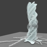
Here are some examples I tried with:
Do you know if that is something that will be addressed or that might become a valid workflow for architects in the future?
I'm trying to get out of my confort zone for weeks. BlenderBIM, FreeCAD and Sverchok. At the same time I have to keep getting my job done in time so I have to keep using the tools I know I can deliver with.
I really felt that FreeCAD was a solid alternative with sketcher. I was amazed at how intuitive and easy it was. Thanks for pointing me to I what @paullee is doing and I hope I can follow something with Sketcher.
@JQL said:
However, I noticed that if I generated building's geometry from the sketches and at a later time added other geometry to the base sketches the whole building model went all over the place.
...
Do you know if that is something that will be addressed or that might become a valid workflow for architects in the future?
João
Yes, I found there are some strength about using sketches as base of wall (so I am exploring this workflow) and weakness, the latter I overcome by some methods which yet to be make public / a better code to be implemented. Currently, each sketch edge Wall segment can have individual Width and Align.
good idea to post these updates here, thanks @bitacovir ... will do myself next time. About your issues with sketches @JQL, sketches are inherently fragile to toponaming issues, and in a sense that is unfixable, because it is the nature of constrained sketches to have their output geometry reshuffled if needed by the constraints. Reshuffling can be optimized and mitigated, of course (i reckon that's what realthunder is doing), but IMHO the issue will always exist. There are many ways to avoid the problem, though. A sketch with 4 connected edges, for example, will always produce exactly one wire. Referencing that wire is perfectly safe. You can also build several sketches of increasing complexity, each one referencing safe edges from the former. The real deal with toponaming is understand what happens, usually when you get there you stop suffering from it
@yorik
Thanks for that info on sketches. Where can I investigate what a wire is so I can use it? If I could safely use sketches I'd definitely use FreeCAD, at least to some extent.
@paullee
I have roughly saw your endeavours and even if I did't fully understood everything yet, it seems your work is mostly focused on windows and their placement. I had a lot of trouble with windows in FreeCAD as they seemed awkward to place and if a wall would change because of some change on the base sketch, then the window would stay put and not connected to the wall.
What I was trying hard to achieve but couldn't get how to do was to define windows based on the sketch geometry. I would place them with plan constraints, that would also affect their width and then state their height placement and total height or height relative to other geometry. The initial thought I had is that a sketch would usually be a floor plan and the windows are vertical (mostly), so my initial thought was to draw sketches for each facade and relate them to floor plan constraints. That would allow me to align the windows with interior geometry, and sketches at other levels.
I couldn't finish that investigation because as the sketches were raising in complexity everything was breaking.
I also bang my head against standard windows and doors. Doors and windows are key in my architecture and I like designing them freely. Standards are too much predefined. I'd love to have windows to be configured with custom profiles. I tried editing the standard windows and I couldn't figure out how.
I bet I would get there eventually but got really frustrated with sketches, so I gave up.
I will give it a second go but I'm honestly a bit sceptical at this point.
@JQL@yorik
Yorik points out some fundamental issues about Sketch in FC, but with due respect, IMHO Sketch should not have suffered from the 'toponaming' problem as discussed Here and could be resolved e.g. in discussion Here.
The situation you suffer should not happen (better to understand if you have a sample model posted here). Thus in my implementation, I am using to build model like Villa Savoye with largely Sketches (some screencapture below), no worry about 'toponaming' problem even with subsequent editing. And some 'pseudo-tutorial' Here. But I have not made my implementation public as I found there is another better approach (Geometry Extension by abdullah) which I yet to experiment.
Anyway don't be mistaken, I am working through using Sketch as Base of Wall to see what are / would be issues there to resolve them along the process, hopefully work out an architect's 'intuitive' workflow. And there are a lot to be done (hope someone may also find there is potential on this route and develop) to make the workflow productive (lot of ideas found in OSArch / FreeCAD forum indeed). As said, each edge / wall segment on a Sketch Wall can now have individual Width and Align as discussed here. Next is cleaning up code to make placement of window intuitive and parametric.
But as Yorik says, make Sketch lighter and with some 'best practice' to workaround the problem you faced. One is IMHO Do Not use Link to External Geometry in Sketch. Again, probably more specific recommendation can be provided with our model.
And you would find Yorik had introduced lots of features useful in Architectural Modeling as announced from time to time in his blog (I like BuildiingPart every much). Though I am more tend to work out a more intuitive and easier workflow for sketch layout and design development.
Just a tip for those new to FreeCAD (like @JQL), @yorik does a development blog (nearly) monthly discussing updates. I recommend you read through some of his posts. Here's the list: https://yorik.uncreated.net/blog/freecad - it's very inspiring and shows how much work has been done! This should totally be shared here regularly!
To myself yes :) Would suggest you try both using Draft Wire (seem more peoples use this) and Sketch to see which workflow suit you (In fact, Arch Wall also generate Base Sketch but usually simple single line)
And there are 'good practice' as Yorik suggest and there are some 'workaround' to overcome some problems without using the experimental workbench I try to do.
Maybe you post the problem (here or in FC forum) so peoples may give you .suggestions.
I'm not quite familiar with wire workflow. I like the sketch based approach because of it's parametric or constrains based geometry generation. It's very easy to understand too so I could pass it on to collaborators. I will provide examples on where it breaks in my case as soon as possible.ni will go through all the info posted here too.
For what I've understood of the very useful info you've shared here, I got some clues to what might be happening with my breaking Sketches.
For me to be able to better share with you the process I followed, I will try to quickly describe it.
My approach to sketches was what I imagined was the most intuitive for a Sketch based architectural workflow. After understanding about the topological naming I have to think on how to adapt it or if I would need to follow a different workflow or how much intuitive would that be for me.
I will share the progress I make on that investigation from time to time, hoping that might also help others.
1 - BASE SKETCH
So, what I did at first was to draw every base line of my building's geometry in floor plan. Like a true first sketch you'd hand draw, but with precise geometry and using a dimension based constrain system. The way I saw it at first was that this was very similar to the Sketches an architect starts with, but instead of loose and vague, it would be accurate and parametric. A natural second step after a paper sketch... I had seen the light! :)
2 - SECONDARY SKETCHES
My initial idea was to pick sketch lines to create walls from and hit the wall button, then pick the slab lines and hit the slab button, and so on. Then FreeCAD would parametrically generate elements based on those lines and whichever chages were made to them.
I soon realized that I couldn't pick individual lines/curves/polylines from the base sketch. So, in order to base my individual building elements, I started building secondary sketches that were connected to the base Sketch. That worked very well by usign the "edge linked to external geometry" tool in the sketcher workbench and picking elements from the Base Sketch as external geometry.
I made a new sketch for each arch element I needed and sometimes I reused the same sketch. That seemed an almost ideal workflow.
Here's a gif of that process:
I understand now that this was where problems stemed from.
Q1: Should we avoid this method altogether?
Q2: If I would use the "four sketch lines that form a wire" method could I safely connect new sketches to that "wire sketch geometry"?
3 - BREAKING SKETCHES
The truth is that as as long as no new geometry would be added to the base sketch this method was working really nicelly. I kept adding new sketches on top of the base sketch, connected to it, and changing base sketch dimensions, angles or constrains was smoothly changing walls and slabs.
However I then tried going back to base Sketch and added an extra wall. This broke every other sketch. Not understanding why that happened, I simply redid the secondary sketches only to have them break again later.
Here's a gif showing what happened:
And another gif where I undo and redo the sketch lines to better show the effects on every secondary Sketch:
4 - MULTIPLE WALLS BASED ON A SINGLE SKETCH
Two of the secondary sketches in this example were baselines for walls. I noticed that if I had all walls in the same sketch sometimes the wall tool didn't generate them. It happened consistently if walls were mixing closed loops with open lines (though right now I can't consistently reproduce it).
So I started splitting my wall sketches into wall types. In this case having a sketch for exterior wall and another for interior walls worked. It resulted into two models, one was a continuous wall, for the exterior, the other was a group of several wall elements. Everything seemed fine in FreeCAD however, exporting the file to IFC and opening it on Blender only showed 2 walls. The exterior continuous wall, and a single interior wall element from the multiwall group. Here is an image:
I imagine that IFC doesn't like to have wall geometries that are not continuous and that might be the problem I have there.
However, I'm not thinking that I will be creating an independent base sketch for each wall and honestly the method I used is very convenient as it consistently keeps regenerating walls as changes happen in the base sketch geometry (as you can see in several of the posted gifs).
Of course, introducing a change to the base Sketch that would break the model, would break these walls.
Q3: I wonder if there is an easy method to generate walls, that is similar to the one I used, but doesn't break and at the same time is exportable to IFC?
Q4: @Moult Is this an issue from my method that works geometrically within FreeCAD but is bad practice in IFC and should be avoided or is it a bug in Blender's IFC implementation?
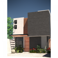
5 - ISSUES WITH WINDOWS/DOORS
Finally I was also investigating on windows and glazing when this happened and I had some issues with them too where I couldn't exactly find the best workflow. Here are some of the issues I had with them:
I couldn't find how to design a façade like the following image and place it on a Sketch base line, splitting the line into N panels. My idea was that when the base Sketch changed the windows would be evenly distributed throughout the line:
Q5: What would be the best method for that, that wouldn't envolve having to copy paste a window component manually?
At the same time, placing windows in a wall and reference their position to the bas.e sketch wasn't straightforward either (I will investigate the method @paullee is using and maybe find some answers there)
I understood that I should change window measurements in the properties panel but I didn't find a nice way to visually change their geometry or relate it with other sketches. That would be key for making the windows align/relate with changing geometry or to visually model them in a wysiwyg approach that I rather work with.
I understood that it wasn't very easy to configure window types. They had a base sketch that was a bit hard to understand how it worked and change it, and I understood that they had predefined settings that would have to be defined from start in an initial dialog, but after placing them I couldn't find how to cycle through the options.
It would be great to have a way to customize or create our own settings and window types.
I also understood that windows were not connected to walls. They had an absolute position in space and so, when a wall changed position, the window would stay put, floating in midair:
Q6: Is it straightforward to create windows and/or façades (windows+walls or windows+structures) based on vertical sketches and have those sketches based on floor plan sketches, instead of inserting windows manually into walls?
I think the most important issues and questions I faced are layed out here. I just tried following what I imagined could be an intuitive approach using the small info I could find about FreeCAD and Sketches and this is a result of a trial and error process that ended up in a dead end for me. I would really appreciate some guidance going forward from here but I hope I'm not pushing my luck, or asking too many questions and making too many bad assumptions as to how and if the software works as it should.
Hi @JQL , the above report is awesome and should be discussed in FreeCAD forum also :)
I am in a hurry to finish some works tonight, hang on, some preliminary observations atm -
It's weird to me you have problem in Q1 to Q3 - as long as you do not delete edges in original Base Sketch, I thought you should be fine with 'dependent' sketch having some Link to External Geometry of the Base Sketch. Can you share your model file to have a close look ? And which version ( 0.18 or 0.19_pre ) and git version you are using. (Copy and paste Help - About FreeCAD - Copy to Clipboard)
If you look at the Villa Savoye Model, the problem / workflow you intended has a preliminary solution there (e.g. Slab outline depends on a master sketch, the whole 1F Wall is based on 1 Sketch etc.)
Q4 - Should have some similar problems I encountered resolved - 2 point first
Do not have more than 2 edges coincident on 1 single point
Do not have edges 'self-intersecting'
Q5 - Check the Villa Savoye model and the discussion thread about Intuitive Placement of Door / Window experiment : Door / Window is just told to place at Wall X, offset from one end by Y mm, at a height of Zmm, that is the workflow I think more intuitive.
Hi again @paulleen and thanks for the feedback. I have tried opening your Villa Savoye Model in my laptop's FreeCAD but I don't think I have the same version as you and it didn't show everything.
My system and version of FreeCAD:
OS: Windows 10
Word size of OS: 64-bit
Word size of FreeCAD: 64-bit
Version: 0.18.4 (GitTag)
Build type: Release
Branch: releases/FreeCAD-0-18
Hash: 980bf9060e28555fecd9e3462f68ca74007b70f8
Python version: 3.6.6
Qt version: 5.6.2
Coin version: 4.0.0a
OCC version: 7.3.0
Locale: Portuguese/Portugal (pt_PT)
I can't send you the model today but will send you tomorrow asap.
Maybe this is better to be discussed elsewhere as we might be deriving this thread.
Curious how you build the spectator stand. Do you try the Stair tool in the workflow? Thanks.
And how about the railing, seem not shown in the FreeCAD model.
If you are using the BIM workbench, you can simply update it from the addons manager. However, part of the enhancements described in the article are in FreeCAD itself. For this, you must wait for a new development release to be produced...
@yorik said:
If you are using the BIM workbench, you can simply update it from the addons manager. However, part of the enhancements described in the article are in FreeCAD itself. For this, you must wait for a new development release to be produced...
Thanks for your help. I'm using Realthunder's branch (as it fixes the problem I had with sketches above) and he updates it fairly regularly . I'm not familiar with how these things work, but if it is a branch should it also carry Current FreeCAD developments? So, do you think that after FreeCAD latest development is released, Realthunder's branch will have those updates too?
the general idea is at some point to have all of realthunder's improvements merged into freecad. But it's a lot of work, because his work is very complicated to integrate, so it goes slowly. I suppose realthunder merges the base freecad code in from time to time, but i can't say for sure..
Awesome update @yorik! It's things like these that once the main OSArch website is up and running as a news outlet we should highlight updates like this!


Comments
That's impressive work Yorik.
I've recently played with freecad sketches for Architecture concepts and was much impressed with how easy it was to create geometric constrains with it and I saw great potential on FreeCAD because of them.
However, I noticed that if I generated building's geometry from the sketches and at a later time added other geometry to the base sketches the whole building model went all over the place. I finally gave up and got back to using Sketchup. However, if that is ever fixed, FreeCAD would become a solid alternative to any other CAD/BIM software I know of. Do you know anything about that, have you found ways of using sketches that dynamically change your models without breaking?
Here are some examples I tried with:
Do you know if that is something that will be addressed or that might become a valid workflow for architects in the future?
Thanks in advance for your reply,
João
You need to leave your comfort zone, man.
What about working on sections of a project and using external references to assembly all together.
@paullee has been working on sketcher for architecture purposes. https://github.com/paullee0/FreeCAD_SketchArch
I'm trying to get out of my confort zone for weeks. BlenderBIM, FreeCAD and Sverchok. At the same time I have to keep getting my job done in time so I have to keep using the tools I know I can deliver with.
I really felt that FreeCAD was a solid alternative with sketcher. I was amazed at how intuitive and easy it was. Thanks for pointing me to I what @paullee is doing and I hope I can follow something with Sketcher.
...
Yes, I found there are some strength about using sketches as base of wall (so I am exploring this workflow) and weakness, the latter I overcome by some methods which yet to be make public / a better code to be implemented. Currently, each sketch edge Wall segment can have individual Width and Align.
A few models e.g. Villa Savoye, Carpenter Center of Visual Art I tried using this workflow - https://wiki.osarch.org/index.php?title=Architecture_3D_models_created_in_FreeCAD
In the meantime, there are some workaround, maybe you post more details and maybe the model about your hiccup.
And yes, use whatever handy to you in the meantime.
And still adding, thinking and soliciting ideas about features to be added in this worflow, e.g. - https://forum.freecadweb.org/viewtopic.php?f=23&t=50802
good idea to post these updates here, thanks @bitacovir ... will do myself next time. About your issues with sketches @JQL, sketches are inherently fragile to toponaming issues, and in a sense that is unfixable, because it is the nature of constrained sketches to have their output geometry reshuffled if needed by the constraints. Reshuffling can be optimized and mitigated, of course (i reckon that's what realthunder is doing), but IMHO the issue will always exist. There are many ways to avoid the problem, though. A sketch with 4 connected edges, for example, will always produce exactly one wire. Referencing that wire is perfectly safe. You can also build several sketches of increasing complexity, each one referencing safe edges from the former. The real deal with toponaming is understand what happens, usually when you get there you stop suffering from it
@yorik
Thanks for that info on sketches. Where can I investigate what a wire is so I can use it? If I could safely use sketches I'd definitely use FreeCAD, at least to some extent.
@paullee
I have roughly saw your endeavours and even if I did't fully understood everything yet, it seems your work is mostly focused on windows and their placement. I had a lot of trouble with windows in FreeCAD as they seemed awkward to place and if a wall would change because of some change on the base sketch, then the window would stay put and not connected to the wall.
What I was trying hard to achieve but couldn't get how to do was to define windows based on the sketch geometry. I would place them with plan constraints, that would also affect their width and then state their height placement and total height or height relative to other geometry. The initial thought I had is that a sketch would usually be a floor plan and the windows are vertical (mostly), so my initial thought was to draw sketches for each facade and relate them to floor plan constraints. That would allow me to align the windows with interior geometry, and sketches at other levels.
I couldn't finish that investigation because as the sketches were raising in complexity everything was breaking.
I also bang my head against standard windows and doors. Doors and windows are key in my architecture and I like designing them freely. Standards are too much predefined. I'd love to have windows to be configured with custom profiles. I tried editing the standard windows and I couldn't figure out how.
I bet I would get there eventually but got really frustrated with sketches, so I gave up.
I will give it a second go but I'm honestly a bit sceptical at this point.
Thank you both for your input!
@JQL @yorik
Yorik points out some fundamental issues about Sketch in FC, but with due respect, IMHO Sketch should not have suffered from the 'toponaming' problem as discussed Here and could be resolved e.g. in discussion Here.
The situation you suffer should not happen (better to understand if you have a sample model posted here). Thus in my implementation, I am using to build model like Villa Savoye with largely Sketches (some screencapture below), no worry about 'toponaming' problem even with subsequent editing. And some 'pseudo-tutorial' Here. But I have not made my implementation public as I found there is another better approach (Geometry Extension by abdullah) which I yet to experiment.
Anyway don't be mistaken, I am working through using Sketch as Base of Wall to see what are / would be issues there to resolve them along the process, hopefully work out an architect's 'intuitive' workflow. And there are a lot to be done (hope someone may also find there is potential on this route and develop) to make the workflow productive (lot of ideas found in OSArch / FreeCAD forum indeed). As said, each edge / wall segment on a Sketch Wall can now have individual Width and Align as discussed here. Next is cleaning up code to make placement of window intuitive and parametric.
But as Yorik says, make Sketch lighter and with some 'best practice' to workaround the problem you faced. One is IMHO Do Not use Link to External Geometry in Sketch. Again, probably more specific recommendation can be provided with our model.
And you would find Yorik had introduced lots of features useful in Architectural Modeling as announced from time to time in his blog (I like BuildiingPart every much). Though I am more tend to work out a more intuitive and easier workflow for sketch layout and design development.
Good luck :)
Just a tip for those new to FreeCAD (like @JQL), @yorik does a development blog (nearly) monthly discussing updates. I recommend you read through some of his posts. Here's the list: https://yorik.uncreated.net/blog/freecad - it's very inspiring and shows how much work has been done! This should totally be shared here regularly!
So, if I understand right, it is possible to have sketcher being used safely for architectural workflow, I just have to keep investigating how?
To myself yes :) Would suggest you try both using Draft Wire (seem more peoples use this) and Sketch to see which workflow suit you (In fact, Arch Wall also generate Base Sketch but usually simple single line)
And there are 'good practice' as Yorik suggest and there are some 'workaround' to overcome some problems without using the experimental workbench I try to do.
Maybe you post the problem (here or in FC forum) so peoples may give you .suggestions.
I'm not quite familiar with wire workflow. I like the sketch based approach because of it's parametric or constrains based geometry generation. It's very easy to understand too so I could pass it on to collaborators. I will provide examples on where it breaks in my case as soon as possible.ni will go through all the info posted here too.
Hi @paullee and @yorik
For what I've understood of the very useful info you've shared here, I got some clues to what might be happening with my breaking Sketches.
For me to be able to better share with you the process I followed, I will try to quickly describe it.
My approach to sketches was what I imagined was the most intuitive for a Sketch based architectural workflow. After understanding about the topological naming I have to think on how to adapt it or if I would need to follow a different workflow or how much intuitive would that be for me.
I will share the progress I make on that investigation from time to time, hoping that might also help others.
1 - BASE SKETCH
So, what I did at first was to draw every base line of my building's geometry in floor plan. Like a true first sketch you'd hand draw, but with precise geometry and using a dimension based constrain system. The way I saw it at first was that this was very similar to the Sketches an architect starts with, but instead of loose and vague, it would be accurate and parametric. A natural second step after a paper sketch... I had seen the light! :)
2 - SECONDARY SKETCHES
My initial idea was to pick sketch lines to create walls from and hit the wall button, then pick the slab lines and hit the slab button, and so on. Then FreeCAD would parametrically generate elements based on those lines and whichever chages were made to them.
I soon realized that I couldn't pick individual lines/curves/polylines from the base sketch. So, in order to base my individual building elements, I started building secondary sketches that were connected to the base Sketch. That worked very well by usign the "edge linked to external geometry" tool in the sketcher workbench and picking elements from the Base Sketch as external geometry.
I made a new sketch for each arch element I needed and sometimes I reused the same sketch. That seemed an almost ideal workflow.
Here's a gif of that process:
I understand now that this was where problems stemed from.
Q1: Should we avoid this method altogether?
Q2: If I would use the "four sketch lines that form a wire" method could I safely connect new sketches to that "wire sketch geometry"?
3 - BREAKING SKETCHES
The truth is that as as long as no new geometry would be added to the base sketch this method was working really nicelly. I kept adding new sketches on top of the base sketch, connected to it, and changing base sketch dimensions, angles or constrains was smoothly changing walls and slabs.
However I then tried going back to base Sketch and added an extra wall. This broke every other sketch. Not understanding why that happened, I simply redid the secondary sketches only to have them break again later.
Here's a gif showing what happened:
And another gif where I undo and redo the sketch lines to better show the effects on every secondary Sketch:
4 - MULTIPLE WALLS BASED ON A SINGLE SKETCH
Two of the secondary sketches in this example were baselines for walls. I noticed that if I had all walls in the same sketch sometimes the wall tool didn't generate them. It happened consistently if walls were mixing closed loops with open lines (though right now I can't consistently reproduce it).
So I started splitting my wall sketches into wall types. In this case having a sketch for exterior wall and another for interior walls worked. It resulted into two models, one was a continuous wall, for the exterior, the other was a group of several wall elements. Everything seemed fine in FreeCAD however, exporting the file to IFC and opening it on Blender only showed 2 walls. The exterior continuous wall, and a single interior wall element from the multiwall group. Here is an image:
I imagine that IFC doesn't like to have wall geometries that are not continuous and that might be the problem I have there.
However, I'm not thinking that I will be creating an independent base sketch for each wall and honestly the method I used is very convenient as it consistently keeps regenerating walls as changes happen in the base sketch geometry (as you can see in several of the posted gifs).
Of course, introducing a change to the base Sketch that would break the model, would break these walls.
Q3: I wonder if there is an easy method to generate walls, that is similar to the one I used, but doesn't break and at the same time is exportable to IFC?
Q4: @Moult Is this an issue from my method that works geometrically within FreeCAD but is bad practice in IFC and should be avoided or is it a bug in Blender's IFC implementation?
5 - ISSUES WITH WINDOWS/DOORS
Finally I was also investigating on windows and glazing when this happened and I had some issues with them too where I couldn't exactly find the best workflow. Here are some of the issues I had with them:
Q5: What would be the best method for that, that wouldn't envolve having to copy paste a window component manually?
Q6: Is it straightforward to create windows and/or façades (windows+walls or windows+structures) based on vertical sketches and have those sketches based on floor plan sketches, instead of inserting windows manually into walls?
I think the most important issues and questions I faced are layed out here. I just tried following what I imagined could be an intuitive approach using the small info I could find about FreeCAD and Sketches and this is a result of a trial and error process that ended up in a dead end for me. I would really appreciate some guidance going forward from here but I hope I'm not pushing my luck, or asking too many questions and making too many bad assumptions as to how and if the software works as it should.
Thanks in advance,
João
Hi @JQL , the above report is awesome and should be discussed in FreeCAD forum also :)
I am in a hurry to finish some works tonight, hang on, some preliminary observations atm -
I made a few updates to the text above (it had been written as fast as possible) and added a new question.
Hi again @paulleen and thanks for the feedback. I have tried opening your Villa Savoye Model in my laptop's FreeCAD but I don't think I have the same version as you and it didn't show everything.
My system and version of FreeCAD:
OS: Windows 10
Word size of OS: 64-bit
Word size of FreeCAD: 64-bit
Version: 0.18.4 (GitTag)
Build type: Release
Branch: releases/FreeCAD-0-18
Hash: 980bf9060e28555fecd9e3462f68ca74007b70f8
Python version: 3.6.6
Qt version: 5.6.2
Coin version: 4.0.0a
OCC version: 7.3.0
Locale: Portuguese/Portugal (pt_PT)
I can't send you the model today but will send you tomorrow asap.
Maybe this is better to be discussed elsewhere as we might be deriving this thread.
Hi @JQL , you may like to open a new thread and/or discuss in FreeCAD Draft, Arch & BIM sub-forum
Attaching the model would be very helpful.
Hi @yorik Awesome model shown in your blog !
Curious how you build the spectator stand. Do you try the Stair tool in the workflow? Thanks.
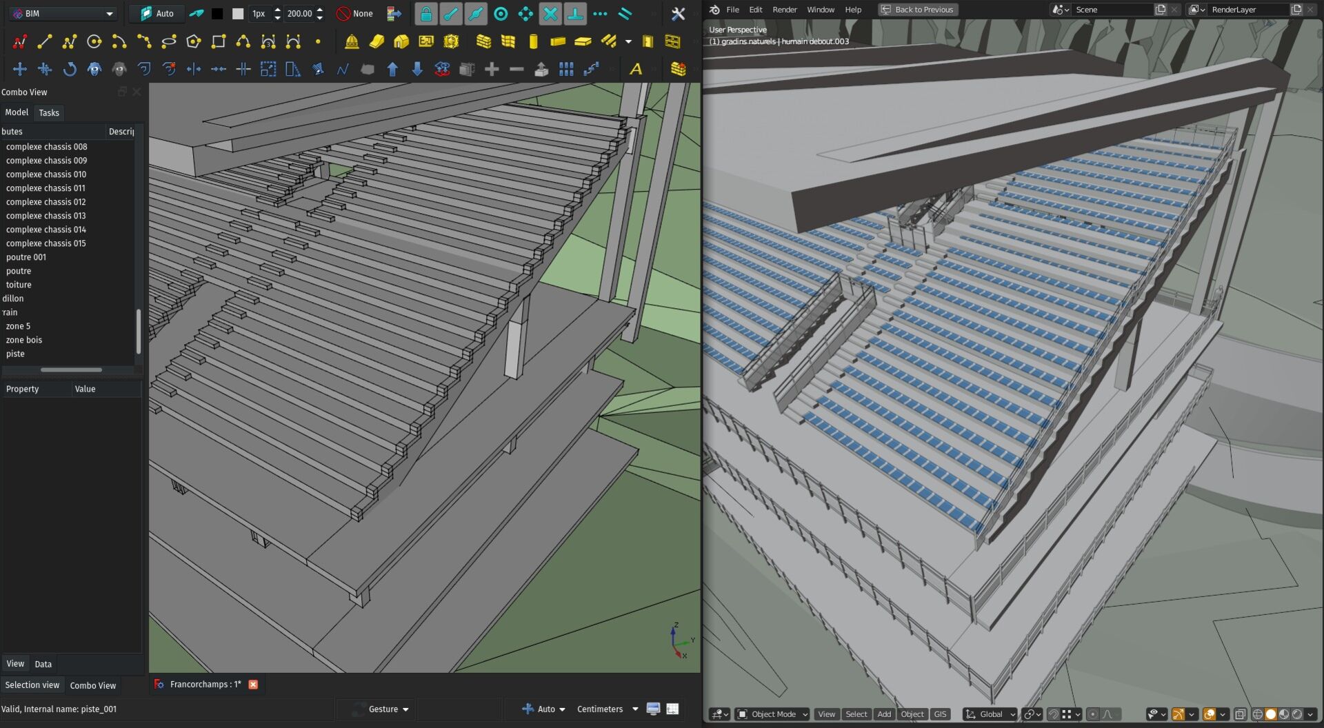
And how about the railing, seem not shown in the FreeCAD model.
@paullee I've posted it on FreeCAD's forum as you requested.
Hi @JQL , it's good you have received a few response :)
And it seems the main issues are indeed solveable:
https://forum.freecadweb.org/viewtopic.php?f=23&t=51653
FreeCAD BIM development news by Yorik - October 2020
https://yorik.uncreated.net/blog/2020-014-freecad-october
You are too fast for me @bitacovir :)
Hi Yorik. Excellent update. I must read everything from here to the initial post though, to see what can be achieved with FreeCAD.
Any of you can tell me where these updates are found, or how they are integrated with my current FreeCAD installation?
If you are using the BIM workbench, you can simply update it from the addons manager. However, part of the enhancements described in the article are in FreeCAD itself. For this, you must wait for a new development release to be produced...
Ohhh! Sorry, sorry! I forgoted you will publish your news here. From now on it is all yours. :)
no worries, i would have done just like you did.. thanks for the help! ;)
Thanks for your help. I'm using Realthunder's branch (as it fixes the problem I had with sketches above) and he updates it fairly regularly . I'm not familiar with how these things work, but if it is a branch should it also carry Current FreeCAD developments? So, do you think that after FreeCAD latest development is released, Realthunder's branch will have those updates too?
the general idea is at some point to have all of realthunder's improvements merged into freecad. But it's a lot of work, because his work is very complicated to integrate, so it goes slowly. I suppose realthunder merges the base freecad code in from time to time, but i can't say for sure..
Awesome update @yorik! It's things like these that once the main OSArch website is up and running as a news outlet we should highlight updates like this!
Latest one! https://yorik.uncreated.net/blog/2021-004-freecad-november-december