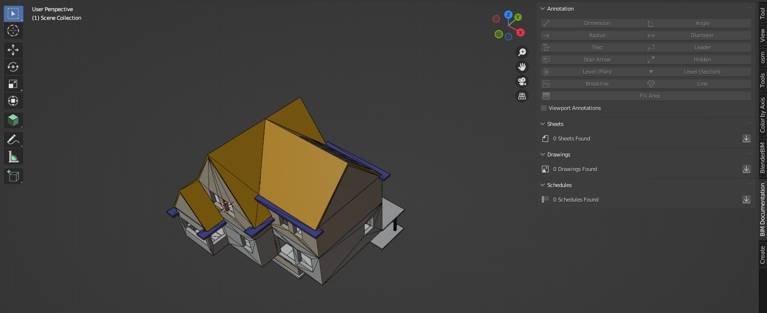
I deleted the sheets and drawings, but the standard Blender grid is gone
How to enable this grid again? Sorry, seems to be a very basic question... but googling gave me all Blender 2.8 results out of date.
It's probably extremely easy, but can't find the button to disable/enable show/hide a grid :-(
Making some good progress with the new documentation tools in BB but have a few questions which I think make sense to consolidate in one post: -
Adding more than a single door/window to a wall type doesn't auto add another boolean, Dion's demo seemed to add booleans for each additional object added. See attached.
Best way to remove tessellation from meshes in plan and elevation views, currently using limited dissolve, not sure if this is best practise?
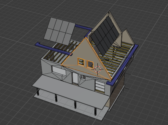
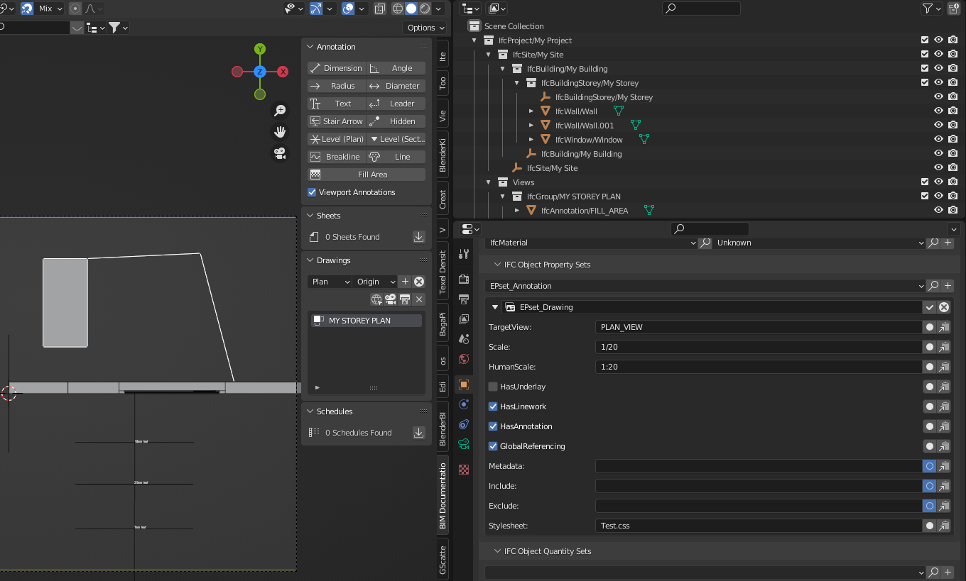
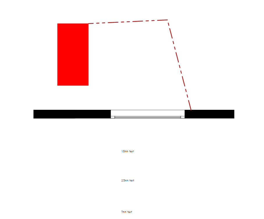
Is there a way to exclude geometry from a specific plan view? Yhe first floor view on the attached shows a pitched roof cut with one of the standard materials applied, ideally this would be hidden from view or displayed with a style which has different styles for cut geometry and background geometry.
For context this is a personal project I'm trying to build our in BB for some renovations works, so low risk and perfect testing this as a workflow.
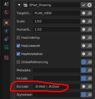
Update to point three; there is an 'exclude' function in the property sets where you can filter objects per view, does anyone know if a list of ifctypes can be inserted here? I've comma separating but no joy.
Also have an issue where I removed a drawing from the ifc file but it is still listed under the sheets and can't be deleted. This is the error, any thoughts?
Update to point three; there is an 'exclude' function in the property sets where you can filter objects per view, does anyone know if a list of ifctypes can be inserted here? I've comma separating but no joy.
Great, thanks. Looking at the link it looks like its possible to also exclude all items from a storey using the GUID? Im not at the computer right now but will test it later.
Ive also mangaed to fix the ifc file by opening in text editor and deleting the rougue drawing manually. Not sure if this is best practise but it was the only way to get the file working again.
Adding more than a single door/window to a wall type doesn't auto add another boolean, Dion's demo seemed to add booleans for each additional object added. See attached.
i think this is a bug, would issue bug report here.
Best way to remove tessellation from meshes in plan and elevation views, currently using limited dissolve, not sure if this is best practise?
yes, i think it is. I think there's a roadmap to improve the 'tesselation of drawings'.
Is there a way to exclude geometry from a specific plan view? Yhe first floor view on the attached shows a pitched roof cut with one of the standard materials applied, ideally this would be hidden from view or displayed with a style which has different styles for cut geometry and background geometry.
@ChubbyQuark said:
Hi, I'm trying to generate some drawings with the latest version of the add-on but annotation text is missing in the viewport, display ok when the drawing is printed.
Encountered this issue as well, tried the different things suggested, still no fix.
Suggestion:
A prominent "Edit IFC" toggle somewhere that only allows you to create ifc elements or edit existing ones rather than regular blender objects, when switched on. When off, you can create or edit only regular blender objects. This way, if switched off, you can create objects in Blender that would not be part of your IFC project's hierarchy, and when switched on, you will only be able to work on objects included in your IFC heirarchy / work within the IFC paradigm.
I don't know if this will have intended consequences, but it will help users consciously work in 'IFC mode' when they need to, ensuring all their objects are IFC elements, unless they consiously choose not to, in which case, they can still manually assign them if they later decide to.
Also, not sure if this should be left till later, if at all, but at this stage, just a thought.
@DADA_universe said:
Suggestion:
A prominent "Edit IFC" toggle somewhere that only allows you to create ifc elements or edit existing ones rather than regular blender objects, when switched on. When off, you can create or edit only regular blender objects. This way, if switched off, you can create objects in Blender that would not be part of your IFC project's hierarchy, and when switched on, you will only be able to work on objects included in your IFC heirarchy / work within the IFC paradigm.
I don't know if this will have intended consequences, but it will help users consciously work in 'IFC mode' when they need to, ensuring all their objects are IFC elements, unless they consiously choose not to, in which case, they can still manually assign them if they later decide to.
Also, not sure if this should be left till later, if at all, but at this stage, just a thought.
Agreed and consider adding something to the UI to remind me in am in the IFC edit mode, may be a graphic, icon or word preferably in a really bright colour
Hey everyone,
Would anyone happen to know how to get the door tag to show like Dion has used here:
@ around 29:00
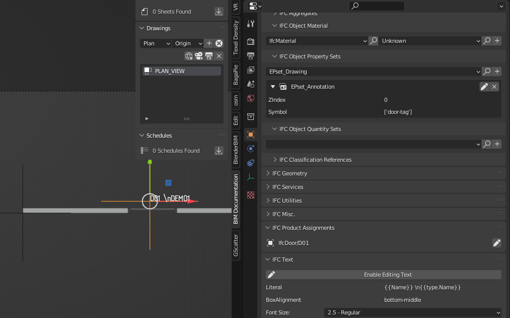
I've got the text related to the door, the text is set as a 'door tag' et al in the preview
but it's not reflecting when I print to svg:
Here's an IFC door tag test file that has the issue if anyone understands:
Anyone know how to use phasing/or custom Psets to set the CSS material/pattern, for example to set all the EXISTING walls as grey?
Phasing status doesn't seem to work yet: https://community.osarch.org/discussion/comment/11810/#Comment_11810
SO I have been using Custom Psets to exclude things which has been good, but now I want to change the pattern using the Pset,
any ideas?
Similar to the discussion here where @globalcitizen used CSS to define this project as red = DEMO,
I know a lot has changed since then
I've attached an example file with walls of different phases/statuses
@Ace see my latest answer in that thread, it's also described on the wiki ( but it would be great to add a working example, I still haven't gotten to do this)
Hey @ChubbyQuark and @JanF
Thanks for the answers!
So I've established you can use your own CSS file by allocating it in the camera:
SVG output with custom lines/hatches:
I got the original CSS to edit from the file path you've both mentioned:
C:\Users\'YOUR USERNAME'\AppData\Roaming\Blender Foundation\Blender\3.2\scripts\addons\blenderbim\bim\data\styles
The CSS file you've created needs to be in the same folder as where the IFC is located to work
I've attached the IFC and the custom Css file (which is saved as a .log because it didnt accept .css for some reason)
In the IFC I have given the wall a "demo" custom Pset. What I want to know is how to apply a CSS to everything tagged with that custom pset, if anyone has more indepth knowledge
@Ace said:
Anyone know how to use phasing/or custom Psets to set the CSS material/pattern, for example to set all the EXISTING walls as grey?
Phasing status doesn't seem to work yet: https://community.osarch.org/discussion/comment/11810/#Comment_11810
SO I have been using Custom Psets to exclude things which has been good, but now I want to change the pattern using the Pset,
any ideas?
Similar to the discussion here where @globalcitizen used CSS to define this project as red = DEMO,
I know a lot has changed since then
I've attached an example file with walls of different phases/statuses


Comments
I thought the following video would work, to create another pattern but BB, doesn't seem to recognize it.
https://www.dropbox.com/s/c3fuad63srfabcn/2022-06-29_10-41-32_New_document_2_-_Inkscape_inkscape.mp4?dl=0
Anyone have any ideas?
https://community.osarch.org/discussion/1016/blenderbim-ifc-annotation-controls#latest
See this discussion on rearranging drawings. (There are two layouts, one where they are linked and you can rearrange them and the finished one)
I deleted the sheets and drawings, but the standard Blender grid is gone
How to enable this grid again? Sorry, seems to be a very basic question... but googling gave me all Blender 2.8 results out of date.
It's probably extremely easy, but can't find the button to disable/enable show/hide a grid :-(
@Coen Go to
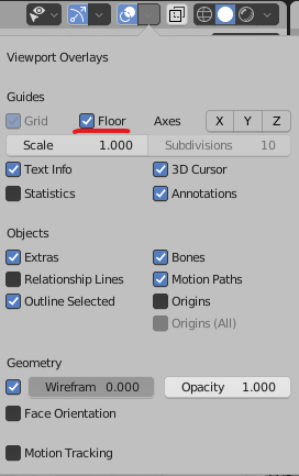
vieport overlaysand check theflooroption:@bruno_perdigao
Thank you!
Thanks @JanF
you're right.
change the file at..
Blender Foundation\Blender\3.1\scripts\addons\blenderbim\bim\data\sheets\...not..
Blender Foundation\Blender\3.1\scripts\addons\blenderbim\bim\data\build\...how to set output to open inkscape
See https://community.osarch.org/discussion/comment/11814/#Comment_11814
Making some good progress with the new documentation tools in BB but have a few questions which I think make sense to consolidate in one post: -
For context this is a personal project I'm trying to build our in BB for some renovations works, so low risk and perfect testing this as a workflow.
Thanks!
Update to point three; there is an 'exclude' function in the property sets where you can filter objects per view, does anyone know if a list of ifctypes can be inserted here? I've comma separating but no joy.
Also have an issue where I removed a drawing from the ifc file but it is still listed under the sheets and can't be deleted. This is the error, any thoughts?
Yes, > @ChubbyQuark said:
yes with
|...Also see https://wiki.osarch.org/index.php?title=IfcOpenShell_code_examples
Great, thanks. Looking at the link it looks like its possible to also exclude all items from a storey using the GUID? Im not at the computer right now but will test it later.
Ive also mangaed to fix the ifc file by opening in text editor and deleting the rougue drawing manually. Not sure if this is best practise but it was the only way to get the file working again.
i think this is a bug, would issue bug report here.
yes, i think it is. I think there's a roadmap to improve the 'tesselation of drawings'.
see video here.
Encountered this issue as well, tried the different things suggested, still no fix.
Fillet still bugging out with the CAD tool when working with lines.
I'm aware this is on the radar, just reporting.
Suggestion:
A prominent "Edit IFC" toggle somewhere that only allows you to create ifc elements or edit existing ones rather than regular blender objects, when switched on. When off, you can create or edit only regular blender objects. This way, if switched off, you can create objects in Blender that would not be part of your IFC project's hierarchy, and when switched on, you will only be able to work on objects included in your IFC heirarchy / work within the IFC paradigm.
I don't know if this will have intended consequences, but it will help users consciously work in 'IFC mode' when they need to, ensuring all their objects are IFC elements, unless they consiously choose not to, in which case, they can still manually assign them if they later decide to.
Also, not sure if this should be left till later, if at all, but at this stage, just a thought.
Agreed and consider adding something to the UI to remind me in am in the IFC edit mode, may be a graphic, icon or word preferably in a really bright colour
Hey everyone,
Would anyone happen to know how to get the door tag to show like Dion has used here:
@ around 29:00
I've got the text related to the door, the text is set as a 'door tag' et al in the preview
but it's not reflecting when I print to svg:
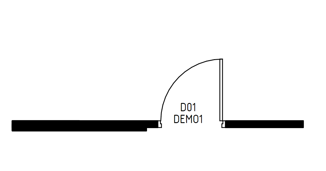
Here's an IFC door tag test file that has the issue if anyone understands:
I've had a bunch of questions which in hindsight should have been part of this conversation so I'm just linking them here:
https://community.osarch.org/discussion/1083/blenderbim-exclude-certain-ifc-elements#latest
https://community.osarch.org/discussion/1066/blenderbim-copying-2d-cad-blocks-as-representations-of-ifctype#latest
https://community.osarch.org/discussion/1073/blenderbim-smart-tag-get-area#latest
https://community.osarch.org/discussion/1085/blenderbim-text-annotation-ui-suggestions#latest
https://community.osarch.org/discussion/1084/blenderbim-how-to-round-dimensions#latest
Anyone know how to use phasing/or custom Psets to set the CSS material/pattern, for example to set all the EXISTING walls as grey?
Phasing status doesn't seem to work yet:
https://community.osarch.org/discussion/comment/11810/#Comment_11810
SO I have been using Custom Psets to exclude things which has been good, but now I want to change the pattern using the Pset,
any ideas?
Similar to the discussion here where @globalcitizen used CSS to define this project as red = DEMO,
I know a lot has changed since then
I've attached an example file with walls of different phases/statuses
Hi Ace, I think you can create your own CCS template to assign paterns/colours to elements. Ill find the relvant file oath if thats what your after?
https://community.osarch.org/discussion/1016/blenderbim-ifc-annotation-controls#Comment_11745
@Ace see my latest answer in that thread, it's also described on the wiki ( but it would be great to add a working example, I still haven't gotten to do this)
Hey @ChubbyQuark and @JanF
Thanks for the answers!
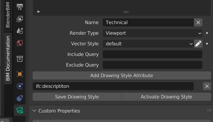
So I've established you can use your own CSS file by allocating it in the camera:
SVG output with custom lines/hatches:
I got the original CSS to edit from the file path you've both mentioned:
C:\Users\'YOUR USERNAME'\AppData\Roaming\Blender Foundation\Blender\3.2\scripts\addons\blenderbim\bim\data\styles
The CSS file you've created needs to be in the same folder as where the IFC is located to work
I've attached the IFC and the custom Css file (which is saved as a .log because it didnt accept .css for some reason)
In the IFC I have given the wall a "demo" custom Pset. What I want to know is how to apply a CSS to everything tagged with that custom pset, if anyone has more indepth knowledge
I'm assuming it's the add drawing style attribute field in camera settings, but i can't get it to work
@Moult Sorry to bother is> @JanF said:
Going down the right path for this task?
This is the convo I meant to reference, whoops, where @globalcitizen has used CSS to mark everything as Demo
https://community.osarch.org/discussion/199/
Anyone know how to control draw order for the Fill and annotation elements? I was mistakenly under the impression it had to do with distance to camera
Maybe you can use this ? https://stackoverflow.com/a/32510121/7092409
Does anyone know how to craete something akin to a plan region from Revit?
https://knowledge.autodesk.com/support/revit/learn-explore/caas/CloudHelp/cloudhelp/2021/ENU/Revit-DocumentPresent/files/GUID-231E2653-8369-4F02-A78E-8A66AF4E4CEE-htm.html
Can you simply create two cameras in different heights and put them together on a layout?